
Abstract
The present paper describes a steel with yield strength exceeding 1900 MPa and fracture toughness in the range of 40–50 MPa m1/2, in its optimum heat treated condition. Its strength is similar to that of 18 Ni (300) grade of maraging steel with good fracture toughness. When tempered at 300°C, it shows tempered martensite along with a small amount of retained austenite phase. The steel shows nearly 25% reduction in weight over typical rolled homogeneous armour (RHA) steel against high velocity hard steel core projectiles. The processing, microstructure, mechanical and ballistic properties of the steel are demonstrated.
Introduction
There are three broad classes of strong steels:
high alloy maraging steels typified by 18 Ni (250)
high alloy secondary hardening steels typified by AF1410
low alloy steels typified by AISI 4340. 1
Further varieties such as Fe–C–Ni–Si–Cr–Co, 1 Fe–C–Cr–Mn/Ni, 2 Fe–C–Si–Cu–Cr–Ni–V 3 have been developed through alloy design to enhance the combination of strength and toughness. Another approach to improvement is microstructural design. Microstructure can be classified into three basic types:
Various alloy design approaches have been used to get these microstructures and to have an optimum combination of strength and toughness.
The highly alloyed ultrahigh strength steels, such as maraging steel, AF 1410, etc., possess high fracture toughness, but their use is confined to areas of critical applications owing to the requirement of higher alloying elements and their high cost. The present work is aimed at the development of Fe–C–Si–Mn–Co–Cr–V steel; its processing and heat treatment to get desired microstructure and phases for armour applications. Ballistic trials of 16 mm thick plates of the above steel against high velocity hard steel core projectiles have shown the steel to be 25% better than typical rolled homogeneous armour (RHA).
Design of alloy
Carbon is the cheapest and most effective element in increasing the strength and hardness of the steel. An appropriate carbon content is selected for strength and weldability, and the carbon level is kept in the range 0·30–0·40% by weight. Silicon content is kept as high as permissible to take advantage of its effect in delaying the onset of tempered martensite embrittlement,1,3,7,8 even though the role of silicon in nickel free steels, in synergetic response with other elements such as cobalt, chromium, etc. is less clear from previous works. Manganese has a powerful effect on hardenability and, as in most steels, has been retained in the range of 0·5 to 1·0 wt-%. Previous work on Fe/Ni/C/Co, 9 Fe/Cr/C/Co 10 and Fe/Mo/C/Co 11 showed that cobalt has no beneficial effect on toughness. However, Malakondaiah et al. 1 have reported an increase in fracture toughness (J1c) of Armco iron as a consequence of cobalt addition and have attributed it to increase in strain hardening exponent. A 0·98 wt-% cobalt was chosen for this alloy. Chromium content is chosen based on the hardenability requirements and to minimise graphitisation tendency caused by silicon. Vanadium is a strong carbide former and helps in grain refinement. It has been reported that nickel has a deleterious effect on the fracture toughness (J1c) of Armco iron. 1 In other studies, it was found that separate additions of nickel do not significantly increase the impact or fracture toughness of the base steel. 7 On this basis, a nickel free steel is conceived. The chosen chemical composition of the steel is as follows: Fe–0·35C–2·0Si–1·0Mn–0·98Co–2·0Cr–0·22V (wt-%).
Experimental procedure
The alloy was melted in an air induction furnace to obtain a 30 kg ingot. After casting and cropping, the ingot was homogenised at 1100°C for 30 h and then hot forged to 70 mm 2 cross-section. The forged alloy was then hot rolled at 1050°C to get 16 mm thickness plates. Samples with dimensions of 150×150×16 mm were cut from the rolled plates and were subjected to heat treatment. The samples were heated above the Ac3 temperature so that complete austenitic (γ) transformation takes place. For this steel, the Ac1 and Ac3 temperatures are 810 and 850°C respectively, as illustrated in Fig. 1. The samples were austenitised at 900°C for 30 min in a neutral salt bath furnace. The samples were then quenched in oil and immediately tempered at the desired temperature. Tempering of these plates was carried in the range of 200–600°C for 1 h followed by quenching in water. The schematic of the heat treatment cycle is given in Fig. 1.
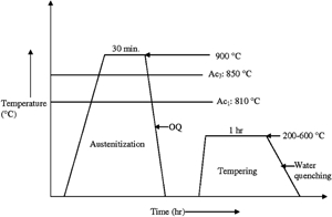
Schematic of heat treatment process. Ac1 temperature gives start of formation of austenite from ferrite–cementite mixture, and Ac3 temperature indicates completion of austenite transformation
Tensile test specimens are machined from heat treated blanks of each experimental condition and are prepared as per the ASTM standard E 8M. 12 The bulk hardness of the target plates are measured according to ASTM E 140-02 using an AFFRI Vickers hardness tester under 30 kg applied load for 15 s. The average hardness of a particular sample is reported from measurements over 10 locations. Standard Charpy V-notch (CVN) impact specimens of 10 mm cross-section are machined from heat treated blanks of each experimental condition with the longitudinal direction parallel to the rolling direction. The CVN of 2 mm depth is machined through the thickness direction perpendicular to the rolling plane. Fracture toughness tests were carried out as per the ASTM standard E 399. 13
Samples representing different tempering temperatures are cut, polished and etched with 2% nital (2 mL HNO3 and 98 mL methyl alcohol) to reveal the microstructure. The steel tempered at 300°C, showing optimum strength and toughness combination is studied under SEM and TEM. The TEM is carried out on a PHILIPS EM 430 electron microscope operating at 300 kV. Specimens for TEM are prepared by twin jet electro-polishing in a 95% acetic acid and 5% perchloric acid (by volume) solution maintained at 0°C. Philips X-ray diffractometer (PW 3020) is used to determine the constituent phases of the specimen tempered at 300°C. Specimens are cut from different regions and polished for the X-ray diffraction (XRD) measurements. Very low force is applied during cutting and mechanical polishing to avoid stress induced transformation of the retained austenite. Fracture surfaces of the Charpy impact samples are observed under a Leo SEM to detect the mode of fracture at different tempering temperatures.
Ballistic experiments are performed in a small arms range using a standard rifle. The schematic of the experimental set-up of the ballistic test is shown in Fig. 2. The small arms range consisted of a firing chamber, a long tunnel and an observation chamber. The gun is mounted on a rigid mount. The target holding fixture is located in the tunnel at a distance of 10 m from the gun. The nominal diameter of the projectiles is 7·62 mm, whereas the actual diameter is 6·06 mm. The mass of the projectile is 5·34 g. The projectile is made of hard steel alloy, and its hardness was 930 HV. The striking velocity of the projectile was 820±10 m s−1, which was measured using infrared light emitting diode photovoltaic cell by measuring the time interval between the interceptions caused by the projectile running across two transverse beams placed 2 m apart. The testing arrangement is also described elsewhere. 14
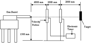
Schematic of experimental set-up of ballistic test
Results and discussion
Figure 3 shows the scanning electron micrograph of the steel tempered at 300°C showing a typical martensitic microstructure. Figure 4 shows the TEM of the steel tempered at 300°C. The TEM photograph clearly shows the presence of lath martensite structure.
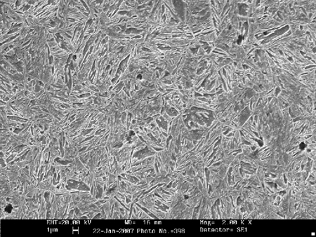
Image (SEM) of natal etched cross-section of steel tempered at 300°C
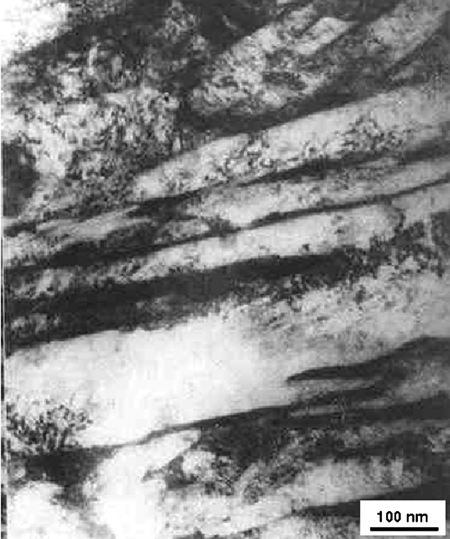
Image (TEM) of steel tempered at 300°C showing lath martensite in microstructure
The XRD result corroborates with the SEM and TEM images (Fig. 5). The XRD result illustrates predominantly Fe-martensite phase along with a small percentage of Fe-austenite phase. The volume fraction of austenite phase has been calculated using XRD technique described elsewhere. 15 It is found that 97% Fe-martensite phase along with 3% of Fe-austenite phase is present in the 300°C tempered steel plate.
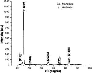
X-ray diffraction pattern of steel tempered at 300°C
Figure 6 shows the variation in mechanical properties of the steel with tempering temperatures. The highest level of strength and hardness is observed in the as quenched condition. This is owing to the transformation to harder martensite phase from austenite during quenching (Figs. 3 and 4). From Fig. 6a, it can be clearly seen that there is an increase in yield strength and ultimate tensile strength on tempering at 200°C. This can be attributed to relief of residual quenching and transformation stresses.16,17 Similar increase in strength of other high strength steels at this stage of tempering has also been reported by previous studies.1,18,19 Negligible drop in yield strength and tensile strength are observed in the tempering temperature range of 250 to 400°C. This can be attributed to the presence of Si in the mentioned range and its effect in retarding softening behaviour of steel while tempering.1,3,7,8 The drop in yield strength and tensile strength observed on tempering above 400°C could be attributed to the ineffectiveness of the kinetic barriers around carbides as a result of increased diffusivity at elevated temperatures. Hardness values follow the same trend as that of strength (Fig. 6b). Martensite formation is accompanied by a large amount of distortion, which rapidly increases the strength and hardness of steel. However, the internal stresses generated during martensite formation cause a significant reduction of the ductility which can be seen from Fig. 6c. Tempering process relieves the internal stresses, and the ductility increases with increasing tempering temperature. Hfowever there is a drop observed in ductility when tempered in the region of 300–500°C. Variation in CVN impact values with tempering temperature is shown in Fig. 6d. The impact energy values increases with increase in tempering temperature up to 300°C followed by a drop beyond 300°C. The drop in ductility and Charpy impact toughness beyond 300°C suggests the occurrence of temper martensite embrittlement (TME). The TME is evident from the SEM of the fracture surface of the broken Charpy impact samples of different tempering temperatures (Fig. 7). Figure 7a is the fractograph of the sample tempered at 300°C showing only dimples on the fracture surface, and Fig. 7b is the fractograph of the sample tempered at 400°C showing quasi-cleavage along with dimple fracture pattern. As a result of embrittlement, there is a change in mode of fracture from complete ductile at 300°C to a mixed mode type of fracture at 400°C. In the case of AISI 4340 steels, the occurrence of tempered martensite embrittlement has been observed at 300°C. 20 However, in the present study, the shift in occurrence of TME beyond 300°C can be attributed to the presence of high weight percentage of silicon in the steel. In the case of high strength DMR-1700 steel also containing similar silicon weight percentage as that of the present study, TME is reported to be observed beyond 300°C. 18
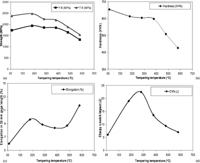
Variation in a yield and ultimate tensile strength; b hardness; c percentage elongation; and d Charpy V-notch impact toughness of claimed steel with tempering temperature

Fracture surface of Charpy impact sample of steel tempered at a 300°C and b 400°C
From Fig. 6, optimum tensile properties and impact toughness combination were found in samples tempered at 300°C. The fracture toughness (K1C) values of the steel tempered in the temperature range of 300–400°C lie in the range of 40–50 MPa m1/2, which is marginally lower than that of maraging steel 300 grade (45–50 MPa m1/2) at such high strength levels. 21 Figure 8 presents a comparison of yield strengths of some of the high strength steels being used as armour, as reported in the literature.19,22,23 It can be seen that the strength of the new steel is higher than the reported values for other steels.
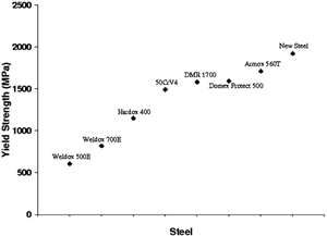
Comparison of yield strength of other high strength steels used as armour with new steel
The steel plates tempered at 300°C were subjected to the ballistic impact of non-deformable steel core projectiles. Three plates were prepared for ballistic evaluation, and each plate was impacted against two non-deformable projectiles to find out the repeatability of the ballistic results. From the ballistic tests, it is found that all the 16 mm thick plates successfully stopped the projectiles. Figure 9 shows the front and rear sides of a steel plate after ballistic test (Fig. 9). A smooth bulge can be seen at the rear side of the plate (Fig. 9b), which indicates that the plate completely stopped the projectile. No cracks are observed either at the front face or back face of the target plates. The RHA plates with a hardness of 340 HV were also tested against the same non-deformable projectiles to compare the ballistic performance of both the steels. Ballistic trials showed that 20 mm RHA plate was required to successfully stop the projectile. Thus, the new steel has an advantage of 25% weight reduction compared to the conventional RHA plates. The improvement in ballistic performance can be attributed to the lath martensite microstructure, 4 a small amount of retained austenite phase in the structure24,25 and high strength and high hardness observed under the optimum heat treated condition.14,23,26
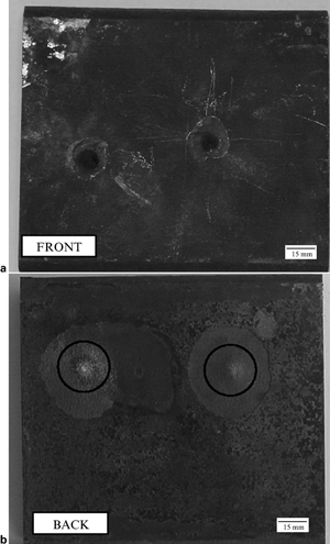
Ballistic results of steel plate tempered at 300°C. Smooth bulges are shown in circles at rear side of plate
Conclusion
It is evident that the strength level achieved in the present steel under the optimum heat treated condition is high and comparable with that of other existing low alloy ultrahigh strength steels. The steel possesses good impact toughness (CVN) at maximum strength levels, and its fracture toughness is close to high alloy maraging steel. On tempering, it shows a delayed occurrence of TME (beyond 300°C). This steel can be potentially used for armour applications and shows a 25% weight reduction in comparison to RHA with a hardness of 340 HV. The impact and fracture toughness of the present steel can be further improved by using cleaner melting techniques.
Footnotes
Acknowledgements
The authors are grateful to the Defence Research & Development Organization (DRDO), India, for financial support which allowed this work to be carried out at the Defence Metallurgical Research Laboratory (DMRL), Hyderabad. The authors are also grateful to the Director, DMRL, for granting permission to publish this paper. The authors thank the Small Arms Range team of DMRL for their help in carrying out ballistic trials. The support rendered by the officers and staff of metallography and mechanical behaviour group is also acknowledged.