
Abstract
In this paper, the TiAl liquid filling process during vertical centrifugal casting into a permanent mould has been described analytically. A model has been established to simulate the forward filling and backward filling process, and two parameters were used to provide a quantitative description of the defect generation that is associated with the forward filling of the mould cavity. One of the parameters used was the forward filling cross-sectional area, and the other was the inclined angle of the free surface of forward filling flow. The cross-sectional area decreases, and the inclined angle increases when the rotational speed increases, the tendency of which becomes more obvious near the mould cavity entrance. The residual volume of the mould cavity after the forward filling is related to the volume of trapped pores. The filling process has also been investigated using numerical simulation. Based on the filling and solidification characteristic of a TiAl valve, the off-centre porosity distribution is also discussed.
Introduction
Gamma TiAl based alloys offer excellent corrosion resistance, oxidation resistance and low density and have attracted a great deal of attention in recent years. The two major potential application fields are the automobile and aerospace industries.1–5 Many traditional forming methods, for example casting, forging and powder condensation, have been evaluated for their use in processing TiAl parts, such as TiAl automobile exhaust valves. 6 The mass of a TiAl exhaust valve is near 50 less than that of the alternative equivalent steel having the same dimensions. Many documents have reported that replacing a steel valve with a TiAl valve could reduce the oil consumption and cut down the noise and exhaust gas pollutions. Many research groups have carried out extensive investigations in this field.7–13 Perhaps, the shape of the valve is seemingly simple. But up to now, no effective production method is widely established. Jones et al. 7 have compared several methods, including static pouring, die casting, injection and centrifugal casting, for making Ti–47Al–2Cr–2Nb (at-) alloy automotive exhaust valves. They suggested that centrifugal casting may be the optimal technique. However, any of those methods has its disadvantages. A joint project carried out by three research institutes and five companies has developed a new manufacturing process, in which melting and centrifugal casting was achieved in a single step. It was reported that the defects of some porosity existed and needed to be hipped to improve the mechanical properties. However, they did not report the distribution of the porosity. 12 Fu et al. 13 investigated the filling and solidification of TiAl exhaust valves under centrifugal force. They reported that the porosity was related to the filling process. However, they did not pay enough attention on this field. Although Wu et al. 14 put forth a model to predict the solidification microstructure of titanium alloys under centrifugal force; no discussion about the defects was provided. In the authors’ casting experiments, the defects were also found, and this paper will introduce some investigation results in this field.
Potential defects found in centrifugal castings of TiAl exhaust valves
The vertical centrifugal casting process for manufacturing TiAl valves is shown schematically in Fig. 1. The detailed shape of a TiAl valve is shown in Fig. 2. The TiAl melt is prepared with induction skull melting furnace.15–17 The TiAl melt pouring from the cold crucible flows through the tundish and arrives at the basin. Driving with the centrifugal force, the melt flows along the cylindrical cavity away from the rotational axis and fills the mould cavity. The defects found in the valves were mainly gaseous pores and off-centre porosity, as shown in Figs. 3 and 4.
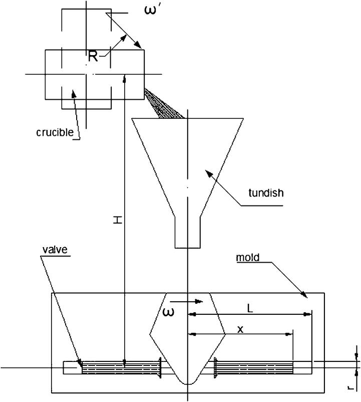
Schematic diagram of foundry system for centrifugal casting of TiAl valves
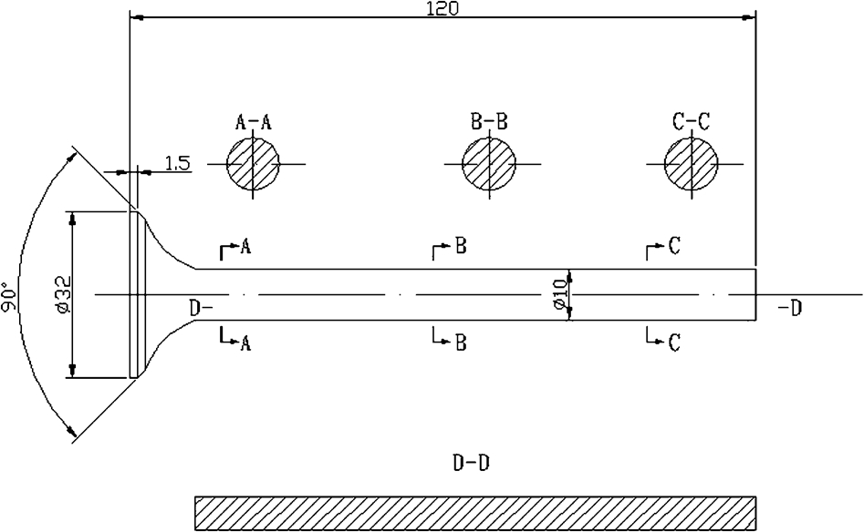
Schematic diagram of exhaust valve structure
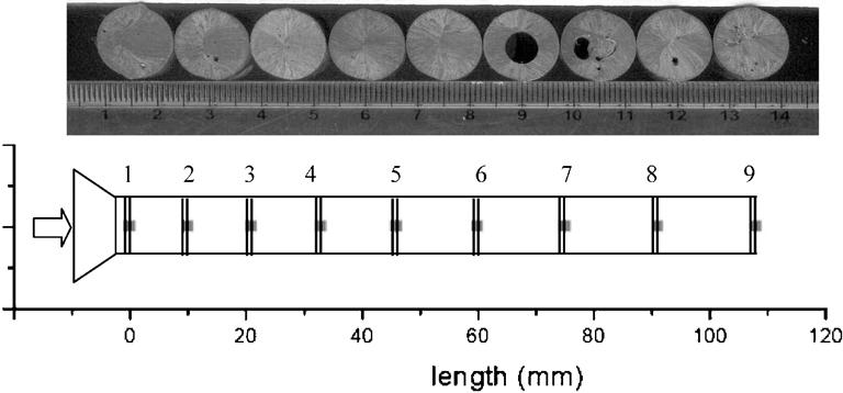
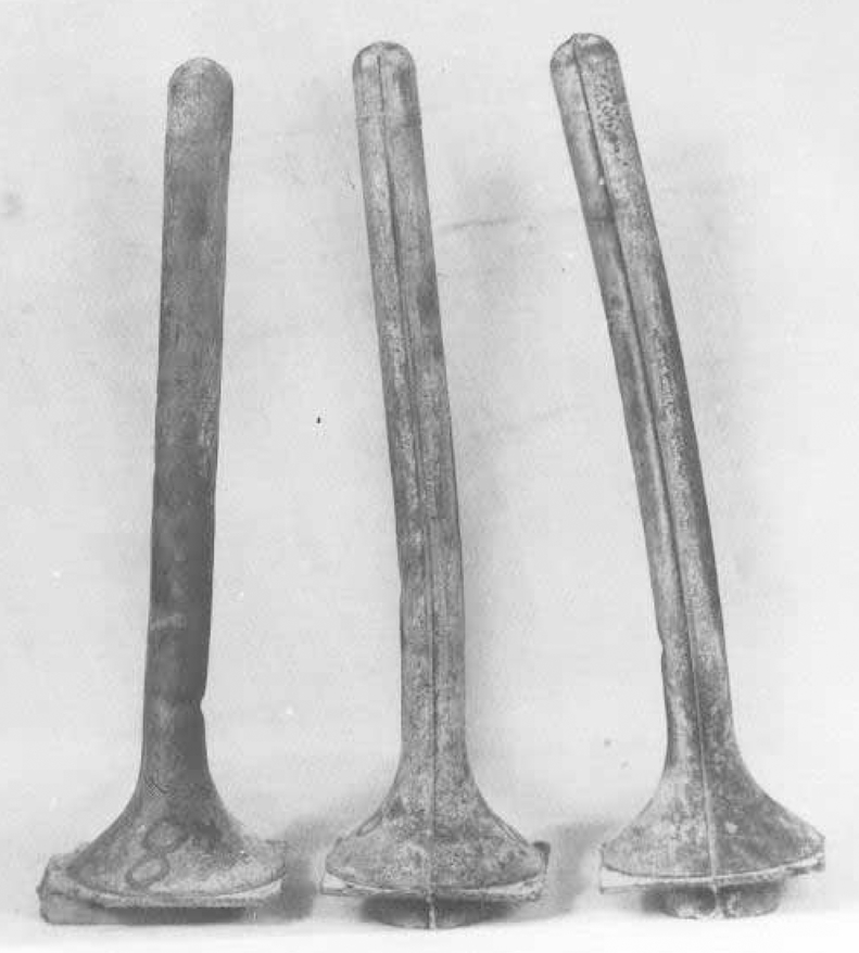
Cross-section characteristics of centrifugal cast TiAl valve (arrow indicates forward filling direction)
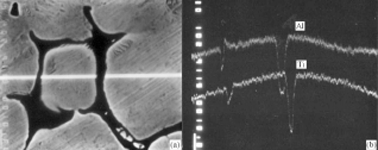
a backscattered electron image; b line distribution of Ti and Al
Generally, the gaseous pores can be produced because of reacting, extracting or entrapping processes. For a permanent mould casting process, the reaction between mould and alloy melt should not introduce any gaseous product. The content of gaseous elements in TiAl melt is less than the solubility under a vacuum atmosphere (∼10 Pa). Therefore, the exudative gaseous element could not form a gaseous pore. Another reason for the formation of gaseous pore is entrapping.
The off-centre porosity is distributed near the centre axis of the valve. The micromorphology of the porosity, as shown in Fig. 4, demonstrated that the porosities are due to microshrinkage, namely the distribution of the off-centre porosity is determined by filling and solidifying of the TiAl melt in the permanent mould.
From the above statement, the authors believe that the two defects are all related to the filling and solidifying processes. The following analysis mainly treats these problems.
Mathematical model of melt flow during vertical centrifugal casting
For the purpose of the model, it is assumed that the valve head will be filled fully with the liquid metal due to the abrupt change of area between the basin and the cylindrical cavity. The filling velocity at this position is defined as the initial horizontal filling velocity v0 (m s−1). The exhaust valve cavity is defined as a column whose radius and length are r and L (L>r) respectively. The rotational rate of the platform is ω (rad s−1). The distance from the rotational axis to the cavity entrance is L0. All the parameters are illustrated in Fig. 5, which also illustrates the static and floating reference frame. A control volume dxi, whose plane normal direction is at i axis, has been chosen to analyse the filling process.
Schematic diagram of flow analysis and reference frames
It is known that the mass flow at any cross-section should be the same value, but the velocity will increase along the i direction. The cross-section area will decrease along the i direction.
Here, the two parameters are defined to describe the centrifugal filling process. They are the cross-sectional area and the inclined angle, as shown in Fig. 6. The cross-sectional area is included by ABCDA. The inclined angle θi(t) is defined as the angle between the arc line and the rotational direction k. The inclined angle θi(t) can be expressed
Schematic diagram for melt cross-section
Based on the above equation, it can be shown that the melt cross-section must decrease continuously due to the increasing filling velocity, and hence, the cavity is only partially filled. To determine the morphology of the cross-section, beside the θi(t), another parameter is necessary. Point A is selected, which is the centre of the chord BD in the x–y–z system as one parameter, as shown in Fig. 6, and the projections on x, y and z are deduced as follows

Description of melt flow state
According to the authors’ experimental conditions, L0 = 0·12 m and v0 = 1 m s−1. Then, the rotational speed is set as 100, 200, 300, 400 and 500 rev min−1 to calculate the cross-sectional areas and inclined angles. The results are shown in Figs. 7 and 8.

Variation of cross-sectional area with filling length (L0 = 120 mm, v0 = 1 m s–1)
Variation of inclined angle with filling length (L0 = 120 mm, v0 = 1 m s–1)
Calculated results indicate that the inclined angle increases gradually during the filling process and becomes more obvious with an increased rotational speed and tends to be 90° at the cavity end. At cavity entrance, the melt separates from the inner wall in different positions (with different inclined angles) under different rotational speed, and the inclined angle increases with increasing rotational speed. In Fig. 8, the value of the inclined angle at the cavity entrance is about 65, 77, 81, 83 and 85° for each successive increasing rotational speed respectively. With the increasing of the inclined angle, the cross-sectional area decreases continually, as shown in Fig. 7.
The centrifugal filling process can be described as follows: the melt enters the cavity with a certain horizontal velocity that is determined by the pouring parameters, cavity geometry shape and rotational speed. Then, the melt fills the cavity along the backwall with an increasing velocity, which leads to the increase in inclined angle and the decrease in cross-sectional area. Near the cavity entrance, the variation tendency is more obvious. The inclined angle of the cross-section at flow end tends to be 90° if the cavity is long enough or the rotational speed is high enough. In other words, the free surface of the cross-section at the flow end tends to be vertical. In addition, the melt separates from the inner wall at a different position when the pouring parameters and the cavity geometry have been changed. This phenomenon is called forward filling and is illustrated in Fig. 9a and b .
a t=0.0118 s; b t=0.0278 s; c t=0.0514 s; d t=0.1214 s
The cavity end will be fully filled first due to the influence of centrifugal force. Sequentially, based on the constant flux at the cavity entrance, the free surface of the backward filling melt moves gradually towards the cavity entrance with a variable velocity that is dependent on v0 and position in the x direction. The cavity is filled completely as soon as the moving melt free surface reaches the entrance and the filling process is finished. The backward filling process is illustrated in Fig. 9c and d.
The above results are only dependent on the analytic relationship. This phenomenon is also treated with numerical simulation using coupled fluid flow and heat transfer.
Figure 10 is the velocity field obtained from the numerical simulation. Section D–D refers to that shown in Fig. 2. The flow state is similar to that shown in Fig. 9. Figure 11 reflects the area and inclined angle and temperature variation at three cross-sections. One can find that at the initial time (TST = 0·112023 for section A–A, TST = 0·064012 for section B–B and TST = 0·064012 for section C–C), the forward filling area decreases along the x direction and the inclined angle increases. When the cross-sectional area is fully filled, the temperature distribution is not symmetrical around the column axis. The hottest point or the last solidified point is different at different cross-sections.
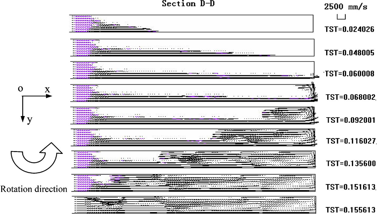
Results of numerical simulation of velocity field during mould space filling
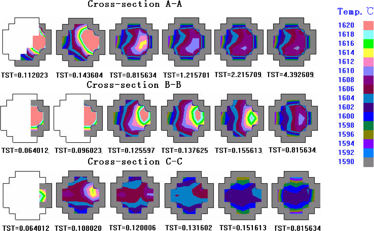
Different cross-section temperature fields of TiAl alloy exhaust valve
Forming mechanism of gaseous pores
The formation of entrapped gaseous pores relates closely with the centrifugal filling process because the gas may be enclosed in the melt during the backward filling process, as shown in Fig. 12. If the enclosed gas cannot be exhausted from the mould vent holes during backward filling, then the gaseous pores will appear near the cavity entrance. Generally, the venting system on a permanent mould is not able to exhaust all the gas enveloped in the last filling zone. It is believed that the bigger the residual volume of the mould cavity after forward filling, the severer the entrapped gas pore will be.
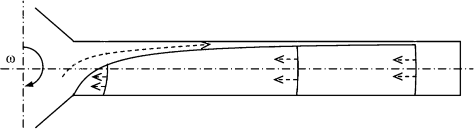
Schematic diagram of formation of entrapped gaseous pores
The residual volume will determine the initial volume of entrapped gas and becomes larger with increasing rotational speed, as shown in Fig. 7. With increasing rotational speed, the forward filling cross-sectional area will decrease; as a result, the residual area will increase. Therefore, the residual volume will increase.
The influence of entrance length L0 and initial horizontal filling velocity v0 on the melt cross-sectional area or the residual volume are shown in Figs. 13 and 14, which indicates that the enclosed gas volume becomes larger with a longer entrance length and a smaller initial filling velocity. Theoretically, a lower rotational speed, a smaller initial horizontal filling velocity and a shorter entrance length combined together is useful to prevent entrapped gas pores.
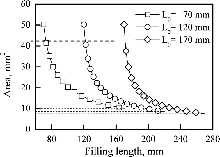
Influence of entrance length on cross-sectional area
Influence of entrance velocity on cross-sectional area
Forming mechanism of off-centre porosity
The formation of off-centre porosity is related to the solidification process. When the process is analysed without quantitatively accounting for the influence of heat transfer, the porosity will distribute near the centre of the backward filling section as shown in Fig. 15. At any section, there are the forward filling area ABDA and the backward filling area ABCA. When the forward filling melt contacts the permanent mould surface, it solidifies partially, and the remaining melt solidified isorate from outer to inner. As a result, the geometry centre is the last solidifying point, i.e. the porosity position deviates from the central axis and towards the rotational direction.
Analytic result of position of off-centre porosity
However, the numerical simulation results of the temperature field during the filling and solidification processes (Fig. 11) showed that the last solidification point is in the forward filling area, which predicts that the porosity within the TiAl valve should be as shown in Fig. 16.
Numeric simulation result of position of off-centre porosity
There are also the forward filling area ABDA and the backward filling area ABCA at any cross-section to consider. Near the entrance and the middle parts, there is a great time difference between the forward filling and the backward filling events. Meanwhile, due to the high temperature of the melt and long contact time between the melt and the mould in the forward filling process, the final solidifying position is near the rear wall in the ABDA (area of forward filling), and the off-centre shrinkage porosity will form here. With increasing filling distance, the cross-sectional area of the forward filling melt, the time difference between the forward and backward filling and the melt temperature difference of forward and backward filling also decrease. Therefore, the final solidifying position gradually moves from the off-centre position to the centre position until the final solidifying position is at the centre axis near the far end, which is shown in Fig. 17. This distribution characteristic of the internal porosity will induce the valves to deform during hipping, as shown in Fig. 18.
Relation between porosity offset and distance
Deformation after HIP treatment of TiAl valves
Conclusions
During vertical centrifugal casting process of TiAl based alloy exhaust valves, the mould filling process consists of forward and backward filling. The cross-sectional area and the inclined angle of the forward filling flow vary with filling length.
Formation of internal defects in the valves relates closely with the filling process in the centrifugal field. Entrapped gaseous pores are formed mainly due to the filling characteristics in the centrifugal field and usually locate near the cavity entrance.
Formation of the off-centre porosity mainly results from the time difference generated by forward and backward filling when the melt passes the same section. Solidification orders are not symmetrical about the central axis and leads to formation of off-centre porosity.
Footnotes
Acknowledgement
The authors would like to acknowledge the financial supported by NSFC (grant no. 50975060) and the Foundation of State Key Lab of Advanced Welding Production Technology of China.