
Abstract
TiC/Ti–6Al–4V composites containing various volume fractions of TiC were produced by induction skull melting and common casting utilising in situ reaction between titanium and carbon powder. The microstructure and room tensile properties of as cast and heat treated TiC/Ti–6Al–4V composites were investigated. Bar-like or small globular eutectic TiC were found in 5 vol.-TiC/Ti–6Al–4V composite, whereas the equiaxed or dendritic primary TiC particles were found to be the main reinforcements in 10 and 15 vol.-TiC/Ti–6Al–4V composites. The as cast TiC/Ti–6Al–4V composites have shown higher strength but lower ductility than those of monolithic Ti–6Al–4V alloy. The shape and fracture of TiC particles can strongly influence the fracture and failure of the composites, and so the ultimate tensile strengths and elongations of as cast composites reduce with the increase in volume fraction of TiC. TiC particles appear to be spheroidised, and titanium precipitation can be found within large TiC particles after heat treatment at 1050°C for 8 h, which can promote the resistance to fracture of composites. Therefore, the elongations of the composites increase significantly, and the ultimate tensile strengths also have marginal increase especially for the 10 and 15 vol.-TiC/Ti–6Al–4V composites after heat treatment.
Introduction
Discontinuous reinforced Ti matrix composites (TMCs) showing high specific mechanical properties, especially the strength at high temperatures and wear resistance, have generated extensive research interests over the past few decades.1–6 Discontinuous reinforced TMCs have been found as a promising material for applications in various fields, such as aerospace, automotive and advanced military applications, because of their low cost and ease of fabrication. 7 7,8 Among the discontinuous ceramic reinforcements, TiC is identified as a very suitable reinforcement for the Ti system because of its excellent properties and good compatibility with Ti matrices. 1 1,6
Discontinuous reinforced TMCs are conventionally produced by solid9–14 or liquid state processes,15–19 and the whisker or particle reinforcements are added by ex situ or in situ route. Blended elemental powder metallurgy is the most popular solid state process to fabricate discontinuous reinforced TMCs, and many researches have been conducted using this technique. 9 9,10 Compared with solid state processes, the liquid state processes for TMCs have the advantages of faster processing rate, large scale production, low cost and flexibility. However, the TiC or TiB reinforcements formed in the liquid state processes are usually coarse in size or unevenly distributed. 1 1,6 This makes the mechanical performance and microstructure of the TMCs unsatisfactory. To solve this problem, the effective and commonly used methods are hot working treatments such as forging, extrusion or rolling after ingot metallurgy,19–21 or rapid solidification processing.22–24 However, if the shapes of TMC products are quite complicated, the common and conventional casting methods without subsequent hot working processes are really attractive due to their advantages of direct casting forming, simplicity, low cost and flexibility.
In the past decade, many researches on conventional casting methods without hot working have been conducted to improve the preparation technology, microstructure and mechanical properties of the discontinuous reinforced TMCs. Dynamet Technology Inc. has developed a technique that uses the powder metallurgy cold and hot isostatic pressing (CHIP) process as a pretreatment process of the subsequent casting. 7 7,18 The CHIP processed billets can be used as feedstock to produce cast TMCs. Then, the melting processing produces a structure with finer and more evenly dispersed TiC particles than that in the starting CHIP processed billets. Lin et al.16 and Zee et al.25 examined the effects of cooling rate and boron content on solidified dendritic TiC in Ti–TiC composites. It was observed that either increasing the cooling rate or the boron additions can decrease the secondary dendrite arm space of TiC and then improve the relative mechanical properties of the composites. Riaz et al.26 investigated the TiC dendrite secondary arm spacing of a series of as cast Ti–C and Ti–Al–C alloys and found that the presence of Al element led to a significant decrease in the dendrite arm spacing, which showed an effect of potential interest on improving mechanical properties. In addition, the effect of heat treatment on Ti–Al–C alloy fabricated by melting process was studied, and a trend of breaking up and spheroidising of dendritic TiC was observed after high temperature heat treatment. 27 27,28 However, the mechanical properties of TMCs fabricated by casting methods are not good enough for the practical applications; thus, further researches are needed to overcome this drawback.
In the present study, the TiC/Ti–6Al–4V composites reinforced with various volume fraction of TiC were synthesised by induction skull melting process. The TiC reinforcements were in situ formed by the reaction between C powder and Ti during melting. The composites were then heat treated at selected high temperatures. The microstructure and room temperature tensile properties of as cast and heat treated composites were investigated, and the relationship between microstructure and mechanical properties has been discussed.
Experimental
For preparing TiC/Ti–6Al–4V TMCs, the raw materials used were sponge Ti (99·8), pure aluminium (99·99), Al–V master alloy and C powder (amorphous C, 0·05 μm). The volume fractions of TiC reinforcements were selected to be 5, 10 and 15 in the present study. In the present study, an induction skull melting furnace manufactured by ALD Co. (Hanau, Germany) was used to produce the composites and monolithic Ti–6Al–4V alloy. Before melting, the sponge Ti and C powder were blended and compacted into blocks, and then these blocks were placed into the copper crucible. The Al–V master alloy and pure aluminium were placed on the top at last in order to prevent the burning loss of Al element and violent self-propagating reaction of Al–Ti–C. During the melting process, the coil power was increased gradually to avoid the violent reactions among the raw materials. After all the raw materials were melted thoroughly, the metal melt was preserved for ∼5 min above the melting temperature in order to ensure the chemical homogeneity by electromagnetic stirring. Finally, the liquid metal was poured into a machined graphite mould to form a plate with thickness of 15 mm. The melting and pouring process was conducted in vacuum (⩽10−1 Pa).
All the samples for microstructural observation and tensile tests were cut from the cast plates. Some samples were cut to study the effect of heat treatment on the microstructure and tensile properties of the composites. The specimens for heat treatment were encapsulated in quartz tubes, which were evacuated to 10−2 Pa vacuum and held for 8 h at 1050°C and then cooled in air.
The microstructures were characterised by Zeiss MC80 DX optical microscopy, FEI-Quanta200 scanning electron microscope (SEM) and Philips EM420 transmission electron microscopy (TEM). Phase identification of the composites was performed by Rigaku D/max-RB X-ray diffractometer.
Flat tensile test specimens with 20 mm gauge length were prepared by electric discharge machining from the cast plates and then mechanically ground and polished. Tensile tests at room temperature were performed in an Instron 5569 testing machine coupled with an extensometer with the crosshead speed of 0·5 mm min−1. The fracture surfaces of the tensile samples were examined using Hitachi S-570 SEM.
Results
X-ray diffraction analysis
Figure 1 shows the X-ray diffraction (XRD) patterns of as cast TiC/Ti–6Al–4V composites containing 5, 10 and 15 volume fractions of TiC respectively. It reveals the presence of α-Ti, β-Ti and TiC phases in the composites. The XRD analysis confirms that TMCs reinforced with TiC can be fabricated by in situ casting technique utilising the reaction between Ti and C. Although the XRD pattern of each sample shows similar profile, the peak intensities of TiC phase increase with volume fractions of TiC increasing from 5 to 15, which implies that more TiC are formed when the C content increases.
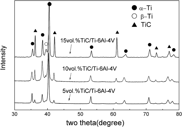
X-ray diffraction patterns of as cast TiC/Ti–6Al–4V composites containing various volume fractions of TiC reinforcements
It can be found that the peaks of TiC shift to high angle gradually with increasing the content of TiC in the composites, as shown in the XRD patterns. This means that the lattice constant of TiC phase decreases gradually. Generally, it is a linear relation between the lattice constant and C content for TiC within a certain range according to the reports of Refs. 27, 29 and 30. By the linear fit equation derived by Brodkin,31 the C content of TiC phase in as cast composites can be calculated. It decreases from 35 to 33 at- with the TiC volume fraction increasing from 5 to 15. This means that the atomic ratio of Ti/C is close to 2∶1, which indicates that C is deficient in solidified TiC phase.
Microstructure of as cast composites
Figure 2 shows the optical microstructures of as cast TiC/Ti–6Al–4V composites. In 5 vol.-TiC/Ti–6Al–4V composite (Fig. 2a), bar-like or small globular TiC particles were mainly distributed along the grain boundaries or interdendrite of Ti matrix. This type of TiC particles are formed by eutectic reaction L→β-Ti+TiC, so are they called eutectic TiC. 27 27,32 Compared with 5 vol.-TiC/Ti–6Al–4V composite, larger equiaxed TiC particles with diameters about 4–7 μm in addition to small eutectic TiC are present in 10 vol.-TiC/Ti–6Al–4V composite (Fig. 2b). The larger equiaxed TiC particles are solidified directly from the melt during solidification process, so they are called primary TiC. 27 27,32 In 15 vol.-TiC/Ti–6Al–4V composite, the primary TiC particles with diameters about 5–10 μm are a little larger than those in 10 vol.-TiC/Ti–6Al–4V composite; moreover, some primary TiC particles grew into dendritic shape as shown in Fig. 2c. In addition, it is observed that the eutectic TiC is rare to find, and the primary TiC is the major TiC phase in 15 vol.-TiC/Ti–6Al–4V composite.
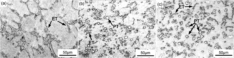
Optical micrographs of as cast TiC/Ti–6Al–4V composites reinforced with a 5 vol.-, b 10 vol.- and c 15 vol.-TiC respectively showing morphology and distribution of TiC reinforcements (ET, eutectic TiC; PT, primary TiC)
Microstructure of heat treated composites
Optical micrographs of TiC/Ti–6Al–4V composite heat treated at 1050°C for 8 h are shown in Fig. 3. Compared with the microstructures of as cast composites (Fig. 2), some changes can be found on the morphology of TiC in heat treated composites. Figure 3a shows that most of the bar-like eutectic TiC appears to have dissolved off and broken up and have distributed discontinuously along the grain boundaries after heat treatment in the 5 vol.-TiC/Ti–6Al–4V composite. In 10 vol.-TiC/Ti–6Al–4V composite, the thin bar-like eutectic TiC can hardly be found, and only finely spheroidised particles are observed after heat treatment, as shown in Fig. 3b. Furthermore, the relatively smaller primary TiC particles became thinner or disappeared, and the corner angles of relatively larger primary TiC particles appear to have dissolved off and spheroidised due to the diffusion of C element during high temperature heat treatment. Similar to 10 vol.-TiC/Ti–6Al–4V composite, the TiC particles in 15 vol.-TiC/Ti–6Al–4V composite are also spheroidised and become isolated, as observed in Fig. 3c. Some dendritic TiC undergoes neck shrinkage at the ‘neck’ of the dendrite arms and breaks up due to C diffusion.
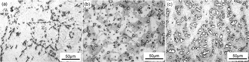
Optical micrographs of heat treated TiC/Ti–6Al–4V composites reinforced with a 5 vol.-, b 10 vol.- and c 15 vol.-TiC respectively showing morphology and distribution of TiC reinforcements after heat treating at 1050°C for 8 h
In addition, some plate-like α-Ti precipitates can be found in some primary TiC particles in the composites containing 10 and 15 volume fractions of TiC reinforcements after heat treatment at 1050°C for 8 h. The larger the TiC particles, the larger the number of Ti precipitates are in the TiC particles. Figure 4 shows SEM and TEM images of the Ti precipitation within TiC particles and the corresponding selected area electron diffraction pattern in the samples that contain 15 vol.-TiC particles. In Fig. 4a imaged by secondary electrons, some plate-like or bar-like precipitates can be observed within the TiC particles after being etched. A TEM image of precipitates within the TiC particle corresponding to the SEM image of Fig. 4a is given in Fig. 4b. The precipitates can be indexed as α-Ti phase according to the selected area electron diffraction pattern as shown in Fig. 4b. Similar results were reported by Jiang,10 Riaz and Flower27 and Hu et al.,33 and it was inferred that the C deficiency in substoichiometric TiC particles is the driving force of Ti precipitation. X-ray diffraction analysis in the section on ‘X-ray diffraction analysis’ indicates that the C content of solidified TiC is obviously lower than the equilibrium composition of TiC at the heat treatment temperature, which corresponds to the composition condition of Ti precipitation. Riaz and Flower27 found that in heat treated TMCs, soft Ti precipitates in TiC can either cause the crack path to deviate or stop the cracks that propagate from the apices of the pyramidal indents during microhardness tests.
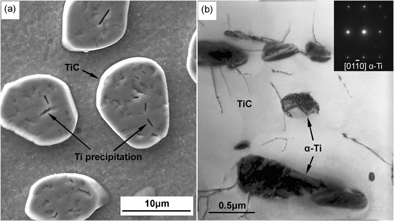
Ti precipitation in TiC particles of 15 vol.-TiC/Ti–6Al–4V composite after heat treating at 1050°C for 8 h
Tensile properties
Table 1 presents the room temperature tensile results for both as cast and heat treated monolithic Ti–6Al–4V alloy and TiC/Ti–6Al–4V composites. These tensile results reveal that the composites have higher yield strength (YS) and tensile strength than the matrix alloy in the as cast condition. The YS of the composites increases with the volume fraction of TiC increasing. However, it cannot be seen as a significant increase in YS with increasing volume fractions of TiC in the 5–15TiC range. In contrast, the ultimate tensile strength (UTS) of composites decreases with increasing volume fraction of TiC, and the 5 vol.-TiC/Ti–6Al–4V composite has the highest UTS. This implies that the fracture resulting from the addition of TiC may have a significant influence on the UTS of the composites. The elongations of all the composites are lower than the matrix alloy and reduce with the contents of increasing TiC.
Tensile properties of in situ synthesised TiC/Ti–6Al–4V composites and matrix alloy
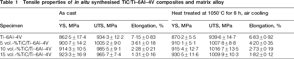
The YS of heat treated composites turns to be slightly higher than as cast samples. However, obvious improvement of the UTS for the composites reinforced with 10 and 15 vol.-TiC can be observed after heat treatment at 1050°C for 8 h. The elongations of all the composites were improved by heat treatment. Unlike the composites, the strengths of monolithic Ti–6Al–4V alloy have no significant increase after heat treatment, and the elongation of heat treated Ti–6Al–4V alloy even reduces, as shown in Table 1. Figure 5 shows the effect of heat treatment on the tensile strength and elongation of the composites. It indicates that the UTSs of the composites with 10 and 15 vol.-TiC increase obviously and are both higher than those of 5 vol.-TiC/Ti–6Al–4V composite heat treated for 8 h at 1050°C. Furthermore, the elongations of heat treated composites increase by 16·7, 19·7 and 38·9 respectively compared with as cast composites. It is worth noting that the strengths and elongations of the composites, especially the composites with 10 and 15 vol.-TiC, increase simultaneously after heat treatment.
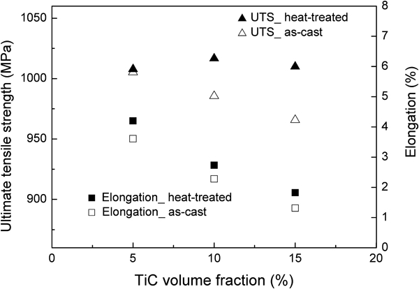
Comparison of UTS and elongation for as cast and heat treated TiC/Ti–6Al–4V composites
Fractography
The SEM images taken from the fracture surfaces and the cross-section near the fracture areas are shown in Fig. 6. The dimples are observed to occupy the most region of the tensile fracture surface in as cast 5 vol.-TiC/Ti–6Al–4V (Fig. 6a). Some small flat facets of fractured particles (particle fracture) are distributed randomly through the fracture surface, and several particle pullout holes can also be seen in Fig. 6a.
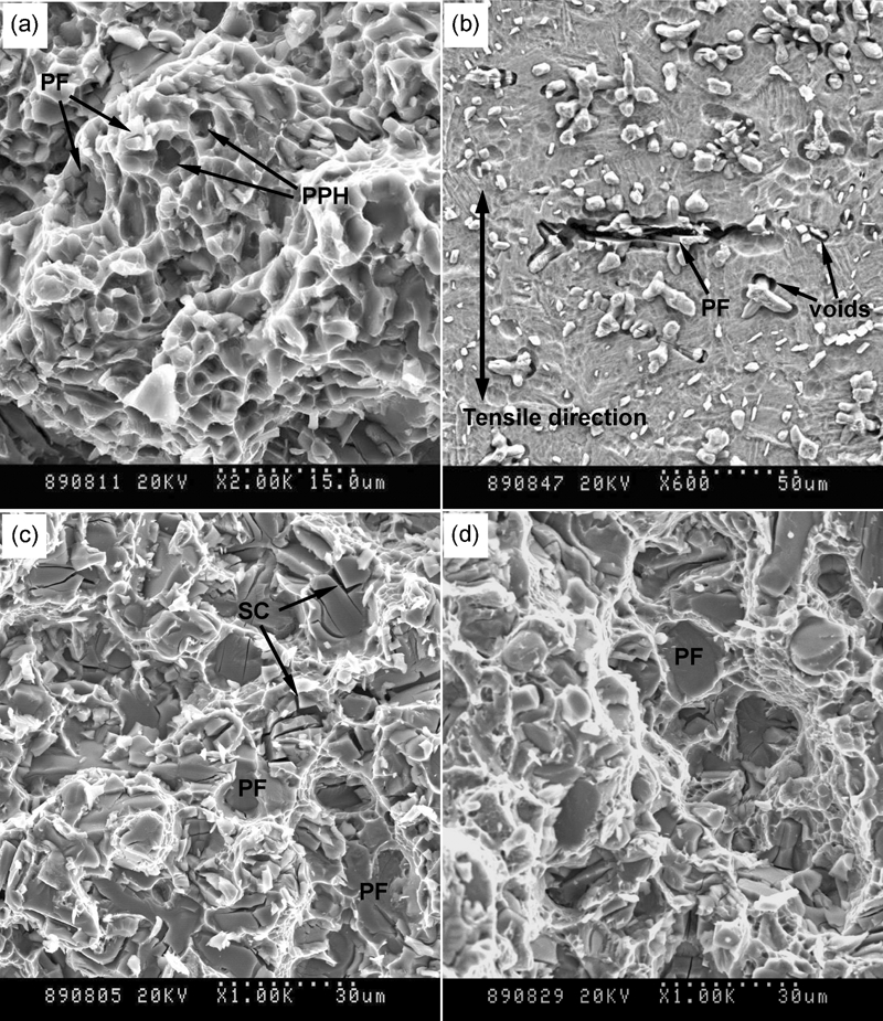
Images (SEM) taken from fracture surfaces of a as cast 5 vol.-TiC/Ti–6Al–4V, cross-sections near fracture surfaces of b as cast 10 vol.-TiC/Ti–6Al–4V and fracture surfaces of c as cast 15 vol.-TiC/Ti–6Al–4V d heat-treated 15 vol.-TiC/Ti–6Al–4V (PF, particle fracture; SC, secondary cracking; PPH, particle pullout holes)
Figure 6b shows the SEM image on a cross-section near the fracture surface from the tensile sample of 10 vol.-TiC/Ti–6Al–4V composite. It indicates that cracks are easy to be generated first in the big primary TiC particles and are especially easy to develop along the dendrite arms in dendrite TiC. Some microvoids can also be found at the interface between TiC and the matrix. The fracture of TiC or cracks can be derived from the voids. Most microvoids are caused by the stress concentration around TiC or the sharp corner angles of TiC. If the stress concentration or sharp corner angles of TiC can be reduced, the number of microvoids would decrease.
Fracture surface of the as cast 15 vol.-TiC/Ti–6Al–4V composite is shown in Fig. 6c. The fracture surface is composed of smooth cleavage planes of TiC and the dimples or tear ridges of the matrix, which shows the characteristic of quasi-cleavage fracture. Most TiC particles on the fracture surface are torn directly and secondary cracking has also been observed in the cracked TiC particles in Fig. 6c. This means that the big TiC particles are very brittle and sometimes are shattered before rupture.34
Figure 6d shows SEM image of the fracture surface taken from the heat treated 15 vol.-TiC/Ti–6Al–4V composite. Compared with as cast samples, the heat treated sample also shows the brittle fracture of the TiC particles and ductile fracture of the matrix. However, the amount of the secondary cracks in the ruptured TiC particles decreases in the heat treated sample, as shown in Fig. 6d. It indicates that the toughness or the resistance to crack propagation of TiC particles has been improved very probably by high temperature heat treatment.
Discussion
The TiC/Ti–6Al–4V composites reinforced with various volume fractions of TiC exhibit higher YS and higher UTS than those of monolithic Ti–6Al–4V alloy at room temperature tensile tests. This indicates that the additions of C element really have a strengthening effect on the matrix. However, there is no significant increase in YS with increasing volume fraction of TiC in the 5–15TiC range. This means that the increases in YS for all the composites are approximate with the addition of different volume fractions of TiC. Thus, the contribution of TiC particles on the load transfer is not significant in the composites, which means that the modified shear lag theory 35 35,36 is not suitable to be used to explain the results in this case. Another possible strengthening mechanism is by thermal misfit between matrix and reinforcement, but this is not applicable to the system TiC/Ti, where the thermal expansion coefficients are similar.1 Besides, the composites could be strengthened by the modification of the matrix, such as grain refinement, C in solid solution, etc. Generally, the TiC has an effect of refinement on the microstructure of the matrix. However, as the observed changes of the sizes of grain and α+β colony are not obvious for the composites and monolithic Ti–6Al–4V alloy because of the fast cooling rate, the contribution of refinement to the increase in strength is small. Therefore, C in solid solution would be the primary cause of the strength increase in these composites. On the one hand, as we know, the C contents in Ti matrix of these composites are approximate in the 5–15TiC range because the solid solubility of C in Ti matrix is considerably low according to the Ti–C binary phase diagram.32 A marginal increase in C content would cause marginal strength increase, which corresponds with the variation of the YS of composites. On the other hand, the increment of the YS of composites compared with monolithic Ti–6Al–4V is not more than 60 MPa, which is close to the usual strengthening effect of C in solid solution on Ti matrix.37 For these reasons, the strengthening of composites by solid solution of C is logical. Wagoner Johnson et al.38 have reported a similar result on compression tests of TiC/Ti–6Al–4V composites. They found that there was no obvious increase in compression YS with increasing volume fraction of TiC from 1 to 10, and they also believed the C in solid solution made a maximum contribution to the YS increase in composites. Ma et al.39 have investigated the forged TiC/Ti-1100 composites reinforced with volume fractions of TiC ranging from 0 to 10. They also thought that, compared to Ti-1100 alloy, the strength increase in the composites mainly resulted from the solid solution C in matrix at ambient temperature.
In addition, the UTSs of the as cast composites do not increase but decrease with the volume fraction of TiC increasing from 5 to 15, and the 5 vol.-TiC/Ti–6Al–4V composite has the highest UTS of 1005·2 MPa, as shown in Table 1. For metal matrix composites, the influencing factors of strength are generally quite complicated; therefore, the UTS dose not always have the effect of monotonically increasing with content of reinforcement increasing.40 According to the analysis of fractographies, it can be assumed that the cracking, especially the fracture of TiC particles, is the main reason for the decrease in UTS for the as cast composites reinforced with 10 and 15 vol.-TiC. The premature fracture of TiC particles promotes the generation and propagation of cracks, which results in the decrease in UTS. Comparatively, the larger TiC particles or dendrite TiC with large length/diameter ratio are ruptured more easily than the smaller or equiaxial TiC particles when loading. For 5 vol.-TiC/Ti–6Al–4V composite, as the TiC particles are much smaller than those in 10 and 15 vol.-TiC/Ti–6Al–4V composites, the TiC particles are not easily cracked; thus, the fracture of particles has less influence on the UTS of the composite reinforced with 5 vol.-TiC.
To restrain the crack propagation and the fracture of TiC particles, heat treatment was employed to modify the morphology or microstructure of TiC. Generally, the TiC phase is relatively stable at high temperature, and its melting point Tm is as high as 3067°C.32 However, if the heat treatment procedure is suitable, the morphology of TiC is possible to be changed according to the report by Zhang et al.28 Commonly, to activate the TiC and to promote the diffusion of C atoms, the temperature of 0·3Tm is needed because the comparatively fast transition does not occur below 0·3Tm.41 The temperature 1050°C selected in the present study is above 0·3Tm of TiC phase, which is in accordance with the mentioned principle. After heat treatment at 1050°C for 8 h, many sharp corner angles of TiC particles are dissolved off, and the TiC particles became smooth and spheroidised. Meanwhile, neck shrinkage or breaking up has occurred in some dendritic TiC. These modifications of TiC during heat treatment are controlled by diffusion of C basically, and can be explained by Oswald ripening theory. The spheroidising of TiC particles can decrease the amount of voids and blunt the crack tips to a certain extent. Moreover, since the spheroidising reduces the stress concentration around the TiC particle, the fracture of TiC can be delayed. The breaking up of dendritic TiC reduces the length/diameter ratio and the stress concentration of dendrite arms root, which can also retard the fracture of TiC. Some small TiC particles have a trend of lessening and disappearing after heat treatment as observed in Fig. 3, which has an effect on eliminating agglomeration. It can also reduce the generation and propagation of cracks. In addition, the soft Ti precipitation in TiC particles after heat treatment can either cause the crack path to deviate or stop the crack propagation within the TiC particles,27 which improves the toughness of TiC to a certain degree as indicated in section on ‘Microstructure of heat treated composites’.
All the reasons mentioned above result in the promotion of the resistance to fracture for the composites. Especially for the composites reinforced with 10 and 15 vol.-TiC, the increments of their UTS after heat treatment are 32·2 and 44·2 MPa respectively. Based on the same reason, the elongations of both composites also have been relatively improved by 19·7 and 38·9 respectively after heat treatment. In addition, since the small particles are commonly not easy to be torn during the tensile process, the fracture of TiC particles is not the main reason for the rupture strength of 5 vol.-TiC/Ti–6Al–4V composite; thus, the change in strength after heat treatment is not obvious compared with the other two composites. However, since the agglomeration of small eutectic TiC particles can be reduced by heat treatment, the generation and propagation of cracks in the regions of particles agglomerating can be weaken. Thus, the elongation of 5 vol.-TiC/Ti–6Al–4V composite also increases by 16·7 after heat treatment, which is similar to the changes in elongations of other composites. Consequently, the elongation increase after heat treatment can also be explained by the above discussion that the process of fracture and failure of the composites is retarded and delayed due to the changes of TiC particles.
Conclusions
TiC/Ti–6Al–4V composites containing various volume fractions of TiC were successfully produced by induction skull melting and common casting technique utilising the in situ reaction between Ti and C powder. The reinforcements in 5 vol.-TiC/Ti–6Al–4V composite are wholly composed of bar-like or small globular eutectic TiC, whereas in 10 and 15 vol.-TiC/Ti–6Al–4V composites, the equiaxed or dendritic primary TiC particles are the main reinforcements.
Compared with the monolithic Ti–6Al–4V alloy, the TiC/Ti–6Al–4V composites have higher strength, while the ductility of composites reduces because of the embrittlement of TiC particles. There is no obvious increase in tensile YS of as cast composites with increasing volume fraction of TiC from 5 to 15. The C in solid solution makes a maximum contribution to the YS increase in composites. The UTSs decrease gradually with increasing volume fraction of TiC, owing to the fracture of TiC particles followed by ductile fracture of matrix.
It has been found in the present study that the shape and fracture of TiC particles can strongly affect the UTS and elongation of the composites, especially when the TiC particles are comparatively larger. After heat treatment at 1050°C for 8 h, many TiC particles with corner angles turn to be spheroidised, and some dendritic TiC are dissolved to be broken up. Ti precipitates are found within TiC particles after heat treatment. These changes in TiC can retard the generation and propagation of cracks and the fracture of TiC particles and then promote the resistance to fracture of composites. Thus, the elongations of the composites increase significantly, and the UTSs also increase somewhat especially for the 10 and 15 vol.-TiC/Ti–6Al–4V composites after heat treatment.
Footnotes
Acknowledgements
The authors would like to express their appreciation to Mr L. R. Wang for his experimental assistance in preparing the materials for this investigation.