
Abstract
Laser beam welding (LBW) was used to 2 mm thick titanium matrix composites (TMCs) sheets and microstructure, hardness and tensile properties of butt joints were studied. Welded joints without defects were obtained indicating that LBW is a suitable processing method for TMCs. The results reveal that the fusion zone completely consists of α′ martensite causing an increase of more 27% in hardness compared with that of base metal. The heat affected zone consists of a mixture of α′ martensite and primary α phases. Large gradients of microstructures and hardness are found over the narrow heat affected zone dependent on the β-transus temperature during weld cooling. TiBw with smaller sizes redistribute at grain boundaries in the weld. The joints show excellent strength and they can reach the full strength compared with the base metal with sound welding parameters, which is ascribed to the presence of α′ martensite and refinement of TiBw in the weld.
Introduction
The high specific strength, specific stiffness, superior high temperature mechanical properties and good creep resistance of titanium matrix composites (TMCs) make them attractive for uses in engineering applications including aerospace, automotive, nuclear and power generation industries.1, 2 Noteworthily, in situ reinforcements for TMCs have been under investigation for some time, because the reinforcement has a clean interface and is both thermodynamically and mechanically stable to the matrix alloy.3–5
In order to make practical complex engineering components from such TMCs, a successful secondary manufacturing processes, e. g. machining, joining, is a key technology. Actually, in many cases, the joining and welding method is imperative. In the past, diffusion bonding, 6 friction welding 7 and arc fusion welding 8 have been used to the joining of TMCs. Hirose 9 studied the weldability of SiCf/TC4 composite using laser beam welding (LBW). However, for the engineering applications, it is significant to investigate the feasibility of fusion welding process. Chernyshov 9 believed that in the welding of TMCs, the fusion zone and heat affected zone should be minimized to avoid degradation of mechanical properties due to the reinforcement/matrix reaction at high temperatures. From this point of view, LBW seems to be the most feasible fusion welding process and becomes the only promising alternatives on TMCs joining, because it offers its small welding deformation, narrow softening zone as well as convenient operation, mainly based on the controllable heat source with high energy density and rapid welding speed.10–12 For discontinuously reinforced titanium matrix composites, there are few reports on their weldability and mechanical property of laser welded joints. In this paper, the suitability of laser beam welding of in situ reinforced TMCs has been investigated.
Experimental
The base material used is a hot rolled TMCs sheet with 2 mm thickness. Chemical compositions (wt-%) of matrix alloy are Ti–6·0Al–3·6Sn–4·1Zr–1·0Nb–0·2Mo–0·34Si. Reinforcements are TiB whisker and La2O3 particle with theoretical volume fraction of 1·26 and 0·58% respectively. TMCs have a β transus temperature of 1313 K. As seen in Fig. 1, the microstructure of base material consists of α equiaxed phases (white) with areas of β phases (grey) at grain boundaries. Some whisker-like substances are dispersed in the matrix. Based our previous studies,3, 4, 8 they are TiB whiskers (TiBw) reinforcements. But reinforcements La2O3 are not observed because they are the nanoscale particles. 3
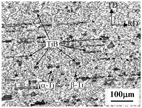
Optical microstructure of base metal
The testpiece (110×40 mm) was firstly pickled using a HNO3/HF acid solution and then cleaned with acetone before welding. Without filler metal, butt welds were made perpendicular to the rolling direction of sheets by a TRUMPF LASMA 1054 laser welding facility with a beam diameter of 0·2 mm. The facility is an Nd:YAG continuous laser with a 1·06 μm wavelength. The focus position during LBW was kept on the top surface of the testpiece. The welding parameters used are listed in Table 1. During welding, both sides of the testpiece were protected by argon (99·99%) with a flowrate of 20 L min−1. After welding, the weld was cross-sectioned along the rolling direction for metallographic and mechanical evaluations by a liner cutting machine. Sectioned samples were prepared using the conventional metallurgy techniques and etched in 0·5 vol.-%HF solution to reveal the microstructure.
Welding parameters used in this investigation
The joint microstructures were examined by optical microscopy (OM, Olympus PMG3), scanning electron microscopy (SEM, JSM-6460) and transmission electron microscopy (TEM, PHILIPS CM200). TEM samples were prepared by twin jet electropolishing. Room temperature tensile test was done to evaluate the mechanical properties of joints using a Zwick/Roell Z020 testing machine at a strain rate of 10−3 s−1, and three samples with a flat surface were made for each welding condition. The dimensions of tensile samples are 20×3·2×2 mm. Microhardness tests across the joint were conducted using a 200 g load for dwell time of 40 s at intervals of 0·2 mm.
Results and discussion
Macrograph of weld seam
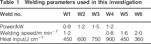
Figure 2 shows the full penetration macrostructure of the laser welds at various welding parameters. The joints show uniform, smooth welds with minor deformation, and no weld defects, e.g. cracks or pores are found in the weld (Fig. 2a). The laser weld exhibits approximate ‘X’ shape and there is a little difference in weld width between the upper and the lower surface of the weld. When the heat input is lower, e.g. 450 J cm−1, there is a visibly an area in the middle of the weld where the fusion lines are parallel. With increasing heat input, the weld width and heat affected zone increases just like the conventional arc welding methods, but the area with parallel fusion line reduces. As the heat input of 900 J cm−1 is applied, the widest width of weldment is obtained (Fig. 2g).
Cross-section of laser beam welds under various parameters
Microstructure of laser weld
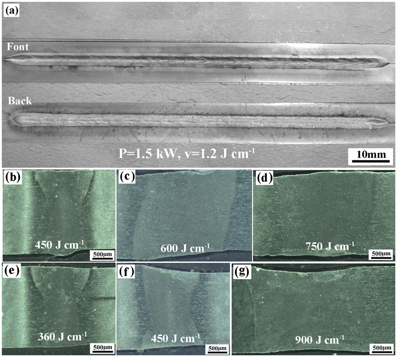
Figure 3 shows the comparison of weld microstructure at various parameters. Similar with the earlier studies, 8 the laser weld also consists of fusion zone (FZ), heat affected zone (HAZ) and base metal (BM). The FZ contains columnar grains and the columnar grain becomes wider with increasing heat input. The HAZ near the FZ (hereinafter termed near HAZ) displays coarse grains. Moreover, the columnar grains in FZ start by epitaxial growth from the near HAZ and develop towards the weld centre. The perpendicularity of columnar grains to the weld centreline is in accordance with this type of solidification. Therefore, the thermal cycle and grain size in the near HAZ dominates the width of columnar grains in FZ. Mohadas 13 proved that, above a critical heat input, e.g. 360 J cm−1 in this paper, the near HAZ will be relatively free from equiaxed primary α because of the exposure of this region to temperature above the β-transus for enough time. Therefore, following this stage, the FZ grain width increases with increasing heat input. By contrast, the HAZ width is narrower compared with the arc welding method 8 due to the controllable heat source and fast welding speed of LBW.
Comparisons of weld microstructure under different parameters
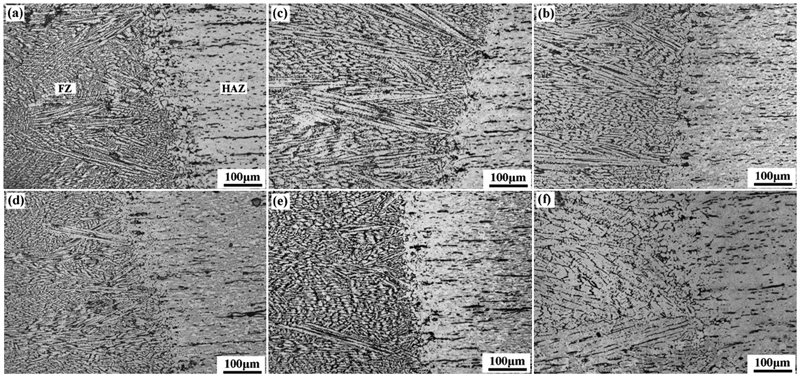
In the weldment, transition region from HAZ to BM is found, as shown in Figs. 3 and 4g–i. The HAZ exhibits dissolution of primary α, and the extent of dissolution of primary α gradually decrease far from the FZ. The microstructure in HAZ consists of a mixture of martensitic α′, acicular α and primary α (Fig. 4g), which corresponds to a sample quenched from temperature below the β-transus. With increasing heat input, the amount of transformed α decrease and the number of primary α and β phase increase due to the lower cooling rate. The acicular microstructures in FZ and near HAZ could not be clearly resolved using an optical microscope (Fig. 3). However, examinations of the structure by SEM (Fig. 4a–f) indicate that the martensitic α′, corresponding to a structure quenched from above the β-transus temperature, constitutes the microstructure of FZ and near HAZ. Martensites α′ intersect each other like a basket weave structure. 14 The martensite lath size is finer, and the α' plates are longer due to higher cooling rate at high speed welding. The acicular product of hexagonal martensite (α') in FZ is confirmed by TEM analysis (Fig. 5a).
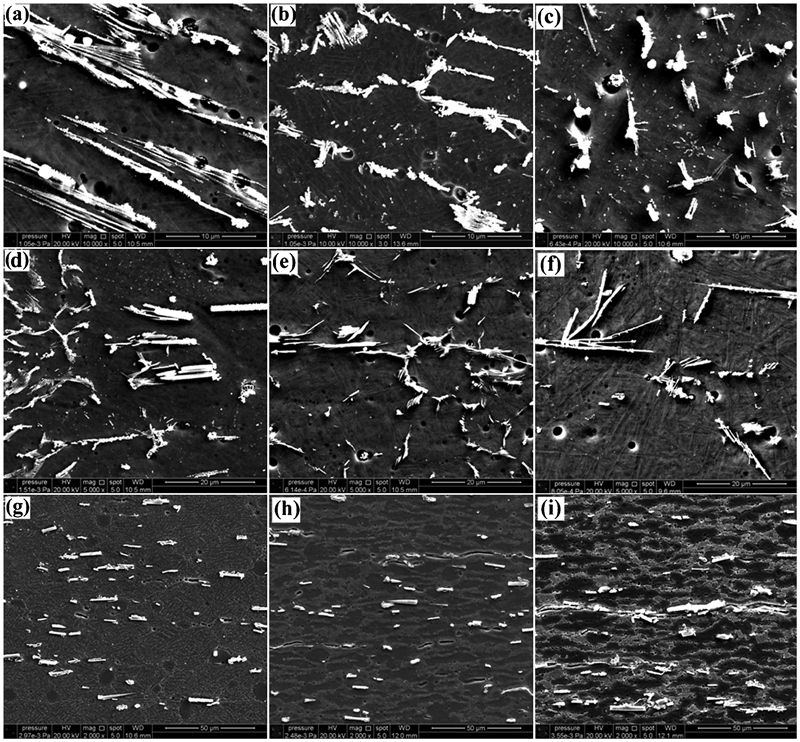
Microstructure of laser weld regions obtained at different welding speeds: for all images, heat input from left to right is 360, 450 and 900 J cm−1 respectively
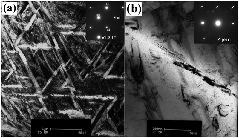
Image (TEM) of a martensitic structure and b TiB whisker in FZ
Moreover, LBW has a great effect on the TiBw, both their distribution and sizes. In FZ and near HAZ, TiBw redistribute at β grain boundaries, showing smaller sizes and a few clusters. Enlarged SEM images reveal that TiBw have a needle shaped morphology (Fig. 4), developing into a network-like structure. Interestingly, in near HAZ, TiBw seem to be divided into parts from a single whisker and become thin and longer, which may reveal the changes of TiBw during the welding. TiBw in HAZ show no distinct changes and might partially become smaller through intensified diffusion of boron due to the effect of thermal cycle. With increasing heat input, TiBw in FZ become smaller in size, and the extent of TiBw clustering reduces. TEM examination proves that TiBw are retained in the weld and maintain good bonding relationship with the matrix during welding, and no undesirable interface reactions or interfacial cracking is found (Fig. 5b).
In welds, the solidification of weld pool often occurs without a nucleation barrier and starts spontaneously by epitaxial growth on the partially melted grains of HAZ (Fig. 3). Those grains that have their easy growth directions closely aligned with heat flow direction will be favoured. Therefore, a columnar grain structure occurs. Besides, TiBw in FZ are thoroughly dissolved in the weld pool due to the low melting point (2473 K) of TiBw. 15 Following the solidification of weld pool, rapid solidification (RS) of liquid titanium containing boron results in the supersaturated solid solution, because boron has a very low solid solubility in titanium. 16 In this paper, boron concentration (0·3 wt-%) in TMCs is below the eutectic point, thus the prior β phases first emerge based on the Ti–B phase diagram. 17 Then the enriched solutes cause constitutional supercooling and TiBw precipitate on subsequent consolidation of the RS products. TiBw has a crystal orientation relationship with the matrix, therefore, the compatible β-Ti/β-Ti interfaces provide an energetic priority nucleation site for TiB, which causes the formation of numerous TiB nuclei. Rapid cooling will reduce the growth rate of TiBw. Afterwards, TiBw grow at β grain boundaries in the weld with smaller sizes in FZ and near HAZ. On subsequent rapid cooling of the weld below the β transus temperature, the diffusionless transformation (β→α′) took place.
Mechanical properties of laser welds
Tensile test
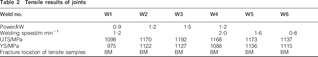
Figure 6 shows a comparison of the mechanical properties of welded joints at room temperature and the test results are listed in Table 2. The ultimate tensile strength (UTS) and yield strength (YS) of BM are 1200 and 1153 MPa respectively. The joints present good mechanical properties and always fail in BM, which reveals that the strength of laser welds is higher than the BM. Of these joints, the lowest UTS and YS are 1098 and 975 MPa respectively, which accordingly reaches 91 and 85% of the BM strength. This suggests that there is a slight reduction in strength of butt joints compared with the BM. With increasing welding parameters, the joint strength is improved. When the laser power of 1·5 kW and welding speed of 1·2 m min−1 were used, the UTS reaches 1192 MPa, which is closely equal to the BM strength. The maximum value, 1136 MPa, for YS of the joint is obtained with power of 1·2 kW and speed of 1·6 m min−1, which is more than 98% of the BM. The superior strength of butt-joints is dependent on the formation of α′ martensite and the refinement and network structure of TiBw in the weld. However, the joint strength shows a decrease trend with further increasing welding parameters. It should be noted that the joints display poor ductility no more than 5%, which is attributed to the presence of martensite α′ in the weld.
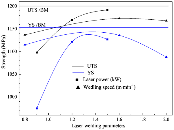
Tensile properties under different welding parameters
Tensile results of joints
As mentioned above, the joint microstructure is visibly refined and α′ laths have smaller sizes during welding. Based on the Hall–Petch theory, the grain refinement effect plays a great role in tailoring the joint strength. Besides, the α′ laths size limited by the β grains size determines the effective slip length, 18 and thus the joint strength is improved. TiBw in the weld become smaller and relocate at β grain boundaries forming the network structure. Huang 1 believed that the network boundary containing TiBw improves the mechanical properties via the network boundary strengthening mechanism. Moreover, the joint strength is also enhanced through the load transfer effect by the shear lag mechanism, 19 which is regarded as one of the strengthening mechanisms for the joint, because in situ TiBw has a clean interface, promoting strong bonding between the whisker and matrix (Fig. 5).
Figure 7 shows the micrographs of fracture surfaces of joints in comparison with the BM. The fracture surface of BM consists of dimples, which indicates that the specimens fail in a ductile manner during tensile deformation. Fine and deep dimples are the characteristic feature of ductile fracture, which validates the higher ductility of BM (Fig. 7a). Cracked TiBw are found to distribute in the fracture surface surrounded by the ductile matrix with tear ridges and dimples, and this reveals that TiBw provides effective load transfer from the matrix during tensile loading. 20 Comparatively, the fracture surfaces of joints exhibit few and rough dimples (Fig. 7b–d), and intergranular fracture mode are found. These prove that the joint has a lower plasticity. Further observations (Fig. 8) show the presence of equiaxed dimples, indicating a microscopically ductile mode of fracture of the butt joint. Especially, surrounding cracked TiBw, larger and deeper dimples are found in the joint fracture surface. This reveals that the matrix experiences a larger plastic deformation during the tensile loading, and TiBw maintain good interface relationships with the matrix and support the load from the matrix until the whisker reaches a critical stress value. With increasing welding speed, the joint displays more coarse dimples, which is mainly due to the increased cooling rate. 11
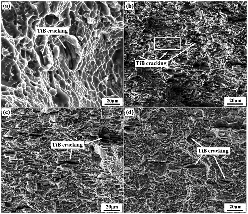
Tensile fracture characteristics of a joints compared with BM: BM; LBW joints at b 0·8 m min−1, c 1·6 m min−1, d 2·0 m min−1
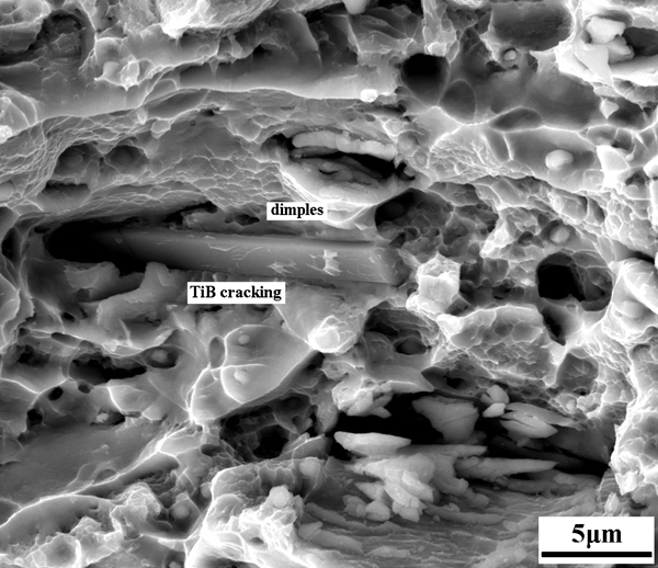
Equiaxed dimples on fracture surface facet indicated by box in Fig. 7b
Microhardness
Figure 9 shows the microhardness distribution across the joint. All joints exhibit the same trend of microhardness. The FZ shows the highest hardness due to the formation of α′ martensite,13, 21 fine and network structure of TiBw. The hardness decrease rapidly in HAZ, and visibly fluctuate from the near HAZ to that near the BM. The hardness variation in HAZ is rather high, approximately from 445 to 528 HV, indicating the heterogeneity in microstructure and mechanical properties over the HAZ. Comparing the hardness of HAZ for all welding conditions, the average values almost are the same, which is ascribed to the narrow HAZ with width of ∼1·0 mm. Besides, the hardness in the joint shows a slight increase with increasing welding parameters. The base metal has an average hardness of 425 HV. The average values in FZ with laser power of 0·9, 1·2, and 1·5 kW are 540, 557 and 575 HV respectively, having a more 27% increase compared with the BM. The average values of 558, 581 and 574 HV in FZ with welding speed of 0·8, 1·6 and 2·0 m min−1, accordingly, show a more 31% increase than that of BM. Actually, the hardness of joints is closely related to their microstructure.21, 22 Generally, the microhardness and strength of existing phases in the joints follow the order: martensite α′>α phase>β phase. 23 In this paper, the joint exhibits the non-uniform microstructure, which is due to the inequable thermal cycle undergone in the weld. The FZ microstructure consists of martensite structure. The near HAZ consists of α′ martensite and partial primary α phase, and the HAZ near the BM includes primary α phase and transformed β containing α′. The base metal consists of α phases and some β phases. Besides, the TiBw size decreases and martensite density increases due to the effect of rapid cooling rate. Therefore, the microhardness in FZ and HAZ are higher than that in BM and increase with increasing welding parameters.
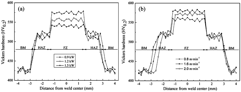
Microhardness distributions of welded joint
Conclusions
Laser beam welding has been used to join titanium matrix composites with thicknesses of 2 mm. The main conclusions are summarised as follows.
The microstructure of TMCs consists of α phases with areas of β phases at grain boundaries. In situ TiBw uniformly distribute in the matrix. The well quality joints were obtained using laser welding for thin TMCs sheets.
The width of FZ and HAZ increase with increasing welding input, and the HAZ width is very narrow. The FZ and near HAZ consists of α′ martensite. The HAZ consists of α′ martensite and primary α phases, whereas the HAZ near BM is composed of primary α and acicular α phase.
In situ TiBw are retained in the weld, and no undesirable interface reactions are found between the whisker and matrix. TiBw have smaller sizes and redistribute at prior β grain boundaries forming the network structure in FZ and near HAZ. With reducing welding input, TiBw becomes thinner and longer.
Microhardness in FZ and HAZ are higher than that in BM, and the maximum values in FZ are obtained. The HAZ presents a high hardness gradient, corresponding to the non-uniform microstructure due to the effect of laser welding. The microhardness of joints increases by more 27% than that of BM.
The joints exhibit superior strength but visibly decrease in ductility. The ductility loss is mainly due to the presence of α′ martensite and TiBw in the weld. The UTS and YS of joints are more than 91 and 85% of the BM strength, and the joint can reach the full strength under rational welding parameters.
Footnotes
Acknowledgements
The authors would like to acknowledge the financial support provided by the 973 Program under grant no. 2012CB619600, the National Nature Science Foundation of China under grant no. 51371114, the Excellent Academic Leaders of Shanghai under grant no. 12XD1402800, and the Dawn Program of Shanghai Education Commission under grant no. 10SG15.