
Abstract
Mg alloy AZ31 was spray-formed using an indigenously developed spray atomisation and deposition unit under protective atmosphere and various processing parameters were optimised. The microstructural features of the bell shaped AZ31 spray-formed deposit were characterised using optical microscope, scanning electron microscope/energy dispersive spectrometer, X-ray diffraction and high resolution transmission electron microscope. It was observed that the microstructural features are critically dependent on location in the spray-formed deposits. Under optimised processing conditions, the central region of the bell shaped deposit exhibited minimal porosity and a uniform fine grained equiaxed microstructure with fine Mg17Al12 intermetallics preferably located at the grain boundaries. However, the peripheral regions of the spray-formed deposit indicate higher porosity with distinct microstructural characteristics different from those in the central region. These microstructural features, observed at different locations in the spray-formed deposit, have been analysed and their evolution is discussed in the light of variations in thermal and solidification conditions of the droplets in flight, during impingement as well as those of the deposition surface.
Introduction
Mg is one of the lightest structural metals being ∼35 lighter than Al. In order to achieve obtain potential weight savings to reduce vehicular emission and improve fuel efficiency, the use of Mg alloy for engineering components in the automotive industry has significantly increased in the past few years. 1 1,2 However, the use of Mg and its alloys was earlier limited due to its poor oxidation and corrosion resistance, poor forming characteristics and low strength levels. During the last decade, these problems associated with Mg alloys have been more or less addressed due to the advances in alloying chemistry of these alloys and significant research in this direction has led to more stronger and ductile alloys with significantly improved corrosion resistance.3 Among them Mg–Al cast alloys (AZ31 and AZ91) are presently the most commonly used in the automobile industry due to their good strength and castability.4
Mg alloys produced by casting based techniques mainly suffer from the inherent problem of alloy segregation and microstructural coarsening. However, these problems associated with conventional casting techniques can be overcome by using spray forming, which is a material processing technique involving rapid solidification process. It is well known that rapid solidification effects, associated with the spray forming, lead to sharp reduction in grain size and microsegregation effects resulting in refined and equiaxed microstructure with substantial microstructural homogeneity in the spray-formed deposit. All of these lead to enhancement of mechanical properties of the spray-formed alloys. Thus, the attractive combination of microstructure and mechanical properties, achievable through rapid solidification, has prompted the use of spray forming process for synthesis of novel alloys with improved properties. Despite this, the published literature on the spray forming of Mg alloys is very sparse,5–8 although considerable amount of work has been reported on other ferrous and non-ferrous alloys and intermetallic compounds.9–11
One of the earliest reports on the spray forming of Mg alloys was by Lavernia et al.5 on Mg–Al–Zr and Mg–Zn–Zr alloys. These studies suggested that microstructures of these alloys were significantly refined (about 30–60 μm) and also exhibited an increase in their mechanical properties on spray forming processing. Chen and Tsao7 have reported spray forming of Mg alloy AZ91 with Si additions to improve their workability. They have also reported a significant reduction in grain size on spray forming with fine intermetallics uniformly distributed in the matrix microstructure. Recently, the microstructure and mechanical properties of spray-formed Mg alloy AZ91 have been studied by Li et al.8 who observed a homogeneous and equiaxed grain structure with average grain size of 20 μm and a significant improvement in their mechanical properties after extrusion. Despite these few reported studies on the microstructure and mechanical properties of Mg alloys, there are no research investigations in the available literature on the mechanism of microstructure evolution in these spray-formed alloys. Moreover, there is also no reported literature on the lattice scale study using high resolution transmission electron microscopy of these spray-formed Mg alloys. It is well known that the mechanical and other properties in crystalline alloys are strongly influenced by the microstructure, hence, the aim of the present investigation is to study the evolution of microstructure in spray-formed Mg alloys.
In the present investigation, indigenously developed spray atomisation and deposition unit has been employed to spray form bell shaped deposits of Mg alloy AZ31 with refined and uniformly distributed equiaxed grain microstructures by means of rapid solidification generated at the atomisation and droplet flight stages. The microstructural features, observed at different locations of the spray-formed deposits, were examined in order to study the evolution of microstructure in the light of solidification of droplets in flight and their subsequent droplet consolidation on the deposition surface.
Experimental procedure
The spray forming experiments were carried out on an indigenously developed spray atomisation and deposition unit, the schematic diagram of which is shown as Fig. 1. One of the features of this unit is the hydraulically controlled water cooled copper substrate, where the atomised droplets impinge, which has the provision of simultaneous rotation as well as vertical downward movement, while water is continuously circulated through it. The continuous rotation of the substrate helps in shaping the deposit while the controlled vertical downward movement aids in maintaining a constant flight distance (distance from the tip of delivery tube to the substrate) during the deposition.
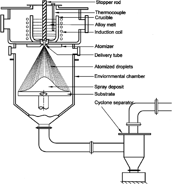
Schematic diagram of spray atomisation and deposition unit used for spray forming of AZ31 Mg alloy
The chemical composition of the Mg cast alloy AZ31, used for spray forming experiments, is Mg–2·8Al–0·84Zn–0·2Mn–0·15Si–0·007Cu–0·005Fe–0·004Ni (wt-). Mg alloy AZ31 ingots were induction melted in a graphite crucible coated with h-BN paint to avoid any contamination. The superheated alloy melt flowing through the ceramic delivery tube was disintegrated into a fine dispersion of micrometre sized droplets by high velocity argon gas jets from the gas atomiser placed concentric to the delivery tube just below the crucible (Fig. 1). The atomisation gas rapidly cools these droplets and directs them towards the hydraulically controlled substrate where they impinge and consolidate to form a spray-formed deposit. The substrate was simultaneously rotated and withdrawn downwards at a constant speed to maintain a constant flight distance during the deposition. Oversprayed powder travelled through a cyclone separator, which has been designed in such a fashion so that the heavier metal particles are accumulated in a collector at its bottom and the gas along with the finer particles goes to the dust collection unit with the help of an exhaust system. Several spray forming experiments were conducted to optimise various process parameters, such as, melt superheat, atomisation pressure, flight distance, substrate withdrawal speed, melt delivery tube inner diameter, etc., in order to obtain dense spray-formed deposits with fine equiaxed microstructure. These optimised processing parameters of spray forming experiments are given in Table 1.
Optimised process parameters used for spray forming experiments
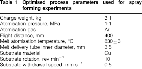
The spray-formed deposits (obtained using the process parameters shown in Table 1) exhibited a bell shaped profile with a base diameter of ∼160 mm and a height of 100 mm, for a melt weight of 3·1 kg. The samples from different regions of the spray-formed deposit were polished using standard metallographic techniques and etched using acetic picral reagent for examination of microstructure. The spray-formed and cast microstructures were analysed using optical microscope (Nikon, EPIPHOT 200), SEM (LEO 440) equipped with energy dispersive spectrometer (EDS, LINK Oxford ISIS 300), X-ray diffraction (XRD, Bruker AXS D8) and high resolution TEM (Tecnai G2 F30 STWIN with FEG source, operated at 300 kV electron accelerating voltage). The sample preparation for high resolution TEM was carried out by mechanical polishing followed by ion beam milling. The density was measured using Archimedes principle employing ethylene glycol as a medium.
Results and discussion
Figure 2 shows the XRD patterns of spray-formed and cast Mg alloy AZ31, indicating the phases present, which were identified using JCPDS standard cards. Initial spray forming experiments indicated a presence of MgO phase in the spray-formed deposits as is evident from the XRD patterns shown in Fig. 2a. It is well known that Mg is very prone to oxidation especially at high temperatures, therefore, special precautions had to be taken in order to avoid oxidation in the spray-formed deposit. Initially, the melting and atomisation chamber was evacuated to a vacuum of ∼1·1 Pa and subsequently backfilled with argon to an overpressure of 0·4 MPa, before melting. In order to further avoid oxidation of the Mg alloy during melting, argon was constantly purged in the chamber while maintaining a positive pressure (above atmospheric) of argon. Figure 2b shows the XRD pattern of AZ31 Mg alloy, spray-formed after taking the abovementioned precautions. The absence of the MgO peaks in this XRD pattern clearly indicates that the precautions taken were effective in avoiding oxidation in spray-formed Mg alloy. The XRD patterns in Fig. 2 also suggest the presence of Mg17Al12 intermetallic phase in both, the spray-formed (Fig. 2a and b) as well as cast alloys (Fig. 2c). The presence of this phase has also been reported by other researchers5–8 in spray-formed Mg–Al alloys and is known to increase the strength and hardness in these alloys.12
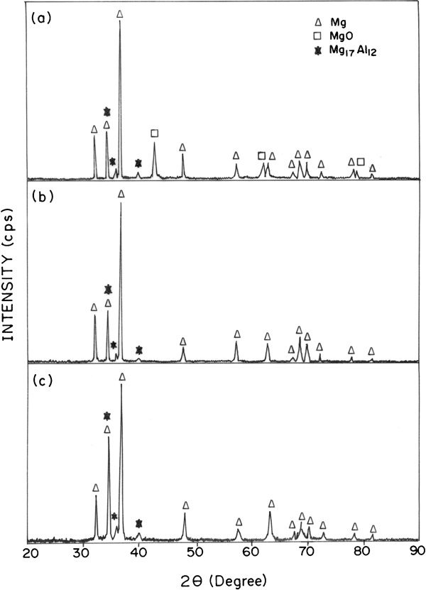
X-ray diffraction patterns of AZ31 Mg alloy a spray-formed deposit from initial experiments showing presence of MgO phase, b spray-formed deposit obtained after optimising process parameters showing absence of MgO phase and c cast mother alloy
Figure 3 shows the optical micrograph of cast mother AZ31 Mg alloy, used for spray forming experiments. This microstructure shows large grains of Mg (about 200–800 μm) surrounded by significantly large worm shaped Mg17Al12 intermetallic aggregate (about 50–250 μm), as identified by EDS analyses, mainly in the intergranular regions. It is expected that in spray-formed alloys, the microstructural characteristics are critically dependent on the location in the spray-formed deposit, as a result of variation in the thermal and solidification environment throughout the material. 13 13,14 Thus in the present studies, the variation in microstructure with location in the spray-formed AZ31 deposit was investigated. The microstructures of spray-formed alloys, synthesised using the optimised process parameters (Table 1), were examined from different regions of the spray-formed AZ31 deposit, which are shown in Fig. 4. Figure 5a shows the optical micrograph from the central upper region of the spray-formed deposit (region a), which shows fine equiaxed grains of about 20–50 μm with Mg17Al12 intermetallic particles of size 6–9 μm uniformly distributed mainly along the grain boundaries. It is apparent from Figs. 3 and 5a that the microstructure of both, the cast and spray-formed AZ31 alloys, consists of Mg17Al12 intermetallic compound, distributed in a Mg matrix, but the microstructure is significantly refined on spray forming. The presence of Mg17Al12 intermetallic phase in cast and spray-formed AZ31 alloys has also been confirmed by XRD studies (Fig. 2).
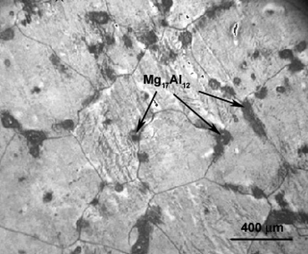
Optical micrograph of cast AZ31 Mg alloy used for spray forming
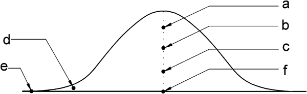
Different regions of bell shaped spray-formed AZ31 Mg alloy deposit which were examined for microstructure
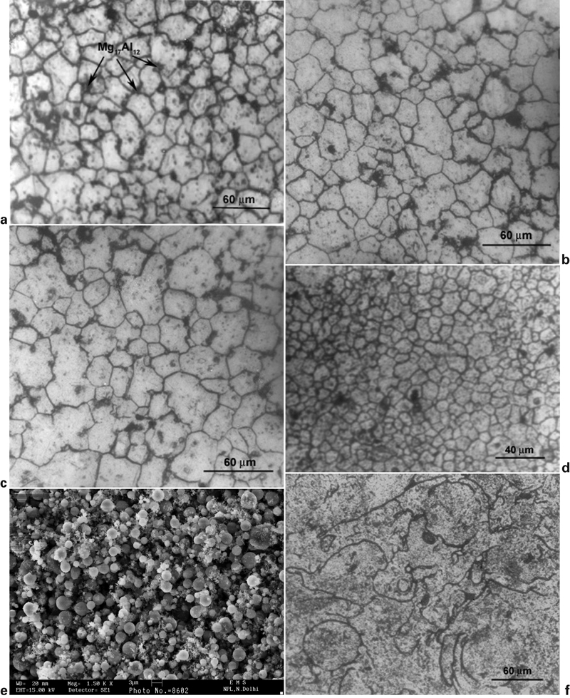
Microstructure at different regions of spray-formed AZ31 Mg alloy deposit
Similar equiaxed microstructures were also found at other central regions of the spray-formed deposit and typical optical microstructures, from central middle and central lower regions (regions b and c) of the spray-formed deposit, are shown in Fig. 5b and c, respectively. During spray forming the withdrawal of the substrate at a speeds nearly equal to the rate at which deposit is growing on the substrate, ensures a constant flight distance, which aids in maintaining nearly uniform microstructure in the entire central region of spray-formed deposit. The porosity throughout this central region of the spray-formed deposit was found to be 2·5–3 and the porosity was observed to be isolated and nearly spherical. Similar values of porosities in central region of spray-formed deposits have also been reported in several spray-formed alloys by different investigators.9,10,15 The porosity in spray-formed deposits is known to arise from gas entrapment, solidification shrinkage or insufficient liquid fraction in the spray plume.10,13,15,16
The near peripheral region of spray-formed deposit (region d) exhibited much lower size of equiaxed grains of about 5–20 μm, as shown in the microstructure in Fig. 5d. The porosity in this peripheral region (region d) was found to be about 7–8, which is higher than that observed in central region of the deposit. Furthermore, the porosity increases sharply towards extreme peripheral region at the edge of spray-formed deposit (region e). In this extreme peripheral region (region e) the porosity was observed to be very high (>30) and the microstructure resembles an agglomerate of loosely bound presolidified particles of grain size 1–4 μm, as shown by scanning electron micrograph of unpolished top surface in Fig. 5e. It is well known that the gas atomisation process, employed to generate the spray, provides smaller sized droplets in the periphery of the spray cone whereas the core of the spray contains relatively large sized droplets.16,17 As a result, relatively high heat exchange rate between small sized droplets and atomising gas generates larger fraction of smaller sized solid particles in the periphery of the deposit, thus leading to higher porosity. In contrast, a coalescence of the spray, with relatively large fraction of droplets in the mushy state, occurs in the central core of the deposit, which is one of the main requirements for obtaining low porosity with equiaxed microstructure.13,16,17 It has also been earlier observed that in several spray-formed alloys the density is maximum along the centreline of the spray-formed deposit and decreases towards the periphery.9,14,15
Figure 5f shows the optical microstructure from the bottom region of spray-formed deposit (region f), which exhibits a layered microstructure with prior droplet boundaries. In this region near the substrate, the microstructure consists of packed powders that arrive on the substrate fully solidified and splats that have deformed upon impact giving this region a higher irregular layered appearance. This microstructure in this region of the spray-formed deposit shows clear evidence of prior particle boundaries that arise from welding between the deformed liquid splats and presolidified droplets arriving at the substrate.
A detailed study of the microstructural features observed in central region of the spray-formed alloys was further carried out by high resolution transmission electron microscopy. Figure 6 shows the bright field TEM micrographs from the central region of the spray-formed deposit, which elucidate the size, shape and distribution of intermetallics in the Mg matrix at a microscopic scale. Although, the optical and SEM micrographs elucidate only the topography of the microstructure at lower magnifications, the TEM micrographs clearly exhibit internal microstructure of grains and intermetallics to a greater extent. It is evident from Fig. 6 that the intermixing of intermetallics (Mg17Al12) with the Mg matrix is clearly observed. In general it was also seen that the intermetallics are denser at the grain boundaries (Fig 6b) rather than within the individual grains (Fig. 6a). These intermetallics are randomly distributed with generally a facetted morphology of about 50 to 100 nm in size (Fig. 6a). The high magnification lattice scale imaging was further performed to understand the interplanar spacings of the matrix phase, intermetallic and the information about the interface between the intermetallic and the matrix (Fig. 7). It is clear from this figure that the individual grains are basically constituted of finer nanoscale crystallites. One such nanoscaled crystallite, constituting the matrix of individual grain shows the interplanar spacing of ∼0·2 nm (plane hkl: 102) and is displayed as an inset in Fig. 7. The intermetallic phase (Mg17Al12) is clearly revealed with interplanar spacing of 0·25 nm (plane hkl: 411, cubic crystal structure), as marked in Fig. 7. It may be noted that the crystallographic orientation relationship between the intermetallic Mg17Al12 and Mg matrix have been discussed earlier by several investigators.12,18 In brief, the orientations of the kind  and
and 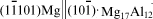 have been elucidated in the literature.18 Although, in the present work, we have not explored the crystallographic relationships of the matrix and the intermetallic, however, a fast Fourier transform calculated from the intermetallic Mg17Al12 clearly indicated the presence of the 411 plane in the reciprocal space (marked with an arrow, inset B in Fig. 7). In addition, the interface between the intermetallic and the matrix was quite clean as no thick grain boundaries are visible. The high magnification evidences in these micrographs (Figs. 6 and 7) further reveal that the process of spray forming leads to a uniform microstructure with ultra fine grained intermixing of matrix phase with the intermetallics.
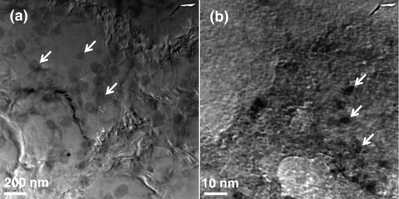
Bright field TEM micrographs from central region of spray-formed deposit showing distribution of intermetallics (indicated by arrows) a within grains and b at grain boundaries
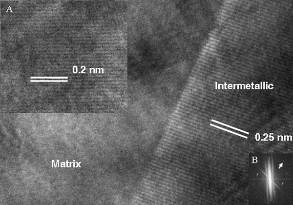
High resolution TEM micrograph showing lattice scale images of intermetallics, nanocrystallites of Mg matrix and interface between intermetallic and matrix: inset A shows interplanar lattice scale image (spacing 0·2 nm) of nanocrystallite of matrix phase and inset B shows fast Fourier transform of corresponding lattice image of intermetallic phase
The microstructural features generated in spray-formed deposit is a combined consequence of the phenomenon which occurs in droplets during their flight and subsequent coalescence on the deposition surface, where solidification and microstructure of spray-formed deposits are governed by the relative magnitudes of solidification time and time interval between the impact of successive droplets.10,13,16 The microstructure is primarily governed by heat flow conditions at the top surface of deposit, which is determined by local rates of heat input of droplets and heat dissipated at deposit surface by conduction and forced convection. During initial stage of deposition, the heat influx from the incoming droplets is less than the rate of heat removal by the substrate and the atomising gas. Therefore, the droplets that arrive onto a cold solid surface are quenched, hence the solidification rate  experienced by these droplets would be greater than the deposition rate
  , i.e.
  . Consequently, the droplets in liquid phase will form a deformed splat and the partially solidified droplets would solidify on impacting the cold substrate. Thus, the microstructure would resemble a layered structure with prior particle boundaries between the deformed splats and the solidified droplets, as is evident from the microstructure of spray-formed deposit in region f (Fig. 5f).
As the perform grows, the heat extraction rate gradually decreases with increasing deposit thickness, consequently, the temperature of the top surface begins to rise and reaches a steady state value. Therefore, the arrival of droplets in liquid or mushy state is such that the heat flux arriving is balanced by the heat extraction rate, thus the individual droplets do not solidify before the arrival of subsequent droplets ( ). As a result, a partially liquid layer forms on the deposition surface giving rise to an equiaxed morphology in the spray-formed deposit, as is evident from microstructures of regions a–c from the central regions of the spray-formed deposit (Fig. 5a–c). The mechanisms responsible for generating equiaxed microstructure from a liquid pool on the deposition surface during spray forming have been earlier discussed by several investigators.10,16,17,19 In general, the formation of equiaxed grains has been rationalised based on the mechanism that partially solidified droplets contain dispersed solid phases at the moment of impingement, and extensive dendritic arm fragmentation during impingement produces a population of potent nuclei. These solid phases and dendrite arm fragments provide a great deal of effective crystalline origins. As a result individual grains grow from these crystalline origins and their growth fronts eventually converge thereby developing an equiaxed grain structure.
It has been pointed out that the imbalance between heat influx and heat extraction rate at the deposition surface must be controlled in order to maintain uniformity in microstructure throughout the deposit thickness.10,16,17,20 This has been carried out, in the present investigation, by maintaining a constant flight distance during the deposition and by optimising different spray forming process parameters that are given in Table 1. The microstructure in the central regions of the spray-formed deposit (regions a–c) and bottom region near the substrate (region f) mainly differ only in the rate of heat extraction, which was higher in the bottom region due to its proximity with the water cooled substrate. As a result, the material present in the bottom region exhibited a heterogeneous morphology with associated prior particle/splat boundaries compared to equiaxed microstructure observed in the central region of the spray-formed deposit.
Conclusions
Spray-formed AZ31 Mg alloy deposits were produced using an indigenously developed spray atomisation and deposition unit under protective atmosphere. The microstructure evolution in these deposits was studied by examining the microstructure at different locations which has been found to depend on the solidification conditions of the droplets in flight, during impingement as well as those of the deposit at the deposition surface. The entire central region of the bell shaped spray-formed deposit indicated a minimal porosity of about 2·5–3 and the microstructure consisted of homogeneous Mg equiaxed matrix of grain size of 20–50 μm with fine uniformly distributed Mg17Al12 intermetallic particles of 6–9 μm. In contrast, the cast mother alloy exhibited large grains of Mg matrix (200–800 μm) surrounded by significantly large worm shaped Mg17Al12 intermetallic aggregate (50–250 μm) in the intergranular regions. The high resolution TEM results in the central region of the spray-formed deposit revealed that the equiaxed grains of Mg matrix are constituted of subgrained microstructure within which ultra fine Mg17Al12 intermetallics (50–100 nm) are randomly distributed. Close to the peripheral region of the spray-formed deposit, the grain size was found to decrease to 5–20 μm with an increase in porosity to 7–8. However, in the extreme peripheral region the porosity increases sharply to ∼30 and the microstructure resembles an agglomerate of loosely bound presolidified particles of grain size 1–4 μm. The microstructure in the bottom region of the spray-formed deposit exhibited a layered structure with clear prior particle/splat boundaries.