
Abstract
In the present work, the formation of ultrafine grained ferrite has been studied by applying suitable thermomechanical treatment. A high amount of deformation (∼80%) at varying strain rates (0·01–10 s−1) was applied in the temperature range of Ar3 to Ac3 followed by water quenching. This treatment resulted in a two-phase ferrite–martensite microstructure as compared to fully martensite structure after quenching without deformation. The formation of ultrafine ferrite (⩽3 μm) during deformation was favourable at a lower temperature and a slower strain rate. A maximum ∼50% ferrite formed during deformation at 780°C with a strain rate of 0·01 s−1. Experimental rolling with a high strain (∼1·3) with finish rolling temperature just above Ar3 (∼750°C) resulted in fine ferrite–pearlite of ⩽3 μm, and the properties showed a high value of strength as compared to steels rolled in a conventional way. Dual phase microstructure (ferrite and martensite) was produced after partial austenisation to 780°C followed by quenching in water, and this resulted in an excellent combination of properties (high ultimate tensile strength, low yield strength/ultimate tensile strength, high elongation and high n values).
Keywords
Introduction
The demand for high strength steels is increasing for various applications, such as automobile, line pipes, construction, etc. Among the various strengthening mechanism, the grain refinement is the only method to improve both strength and toughness simultaneously.1 The main benefit of this approach is to avoid costly alloying elements, avoid additional heat treatment and improve weldability owing to lower alloying content.2 Ferrite refinement achieved by the conventional controlled rolling method results in ferrite microstructure with a minimum grain size of ∼5 μm, whereas research work in many institutions and laboratories are in progress to produce ultrafine grain size below 3 μm using various techniques.3–16 The efforts are on the application of these techniques for commercial production but yet to achieve it. This subject has generated a lot of interest from academicians, researchers and industrialist, leading to many international conferences and publications in the last few years. The application of advanced thermomechanical treatment, particularly heavy deformation at a low temperature, is reported to be useful in achieving ultrafine grain size3–16 by dynamic transformation. In low carbon steel, the effect of various factors on the formation of ultrafine grain size was reported by Choi et al.,4 and they achieved grain size of the order of 2·3 μm as against the 6·5 μm by static transformation. Finer austenitic grain size was reported to be beneficial for finer ferrite grain size.4 Other factors such as strain, strain rate and temperature are reported to be important in achieving finer grain size 3 3,4. The objective of the present work was to study the formation of ultrafine grain microstructure by designing suitable thermomechanical simulator in one microalloyed steel and apply the process to experimental rolling.
Experimental
The chemical composition of the steel taken for the experimentation is 0·08C–1·5Mn–0·3Si–0·011S–0·011P–0·046Nb–0·025Ti–0·057V–0·0073N (wt-%). The steel contains C, Mn and Si with a significant amount of microalloying elements (Ti+Nb+V). The steel was made in 25 kg laboratory scale induction furnace, and then ingots were forged to a 40 mm thick plate. Forged samples were used for thermomechanical processing experiments on a Gleeble-1500. Transformation temperatures were determined by dilatation measurements on the Gleeble-1500 during heating at 5°C s−1 and during cooling at various cooling rates from 1150°C. To investigate the effect of various parameters on the grain size, thermomechanical cycles were designed, which is depicted in Fig. 1. Samples of 6 mm diameter and 10 mm length were heated to 1150°C at 10°C s−1, held for 2 min, and then cooled at 2°C s−1 to a certain temperature (780, 800 or 850°C). At this constant temperature, compressive deformation of ∼80% (ϵ = 1·6) was applied at various strain rates of 0·01, 0·1, 1 and 10 s−1. After this treatment, the samples were quenched in water from that temperature (Fig. 1b). Initially, the experiment was also conducted without applying any deformation using the same thermal cycle (Fig. 1a) to compare the microstructure with that of deformation and to evaluate initial austenitic grain size. The aimed deformation was 80%, but in actual experiments, deformation varied between 76 and 82%. Optical and scanning electron microscopy studies were conducted to evaluate the microstructural phase and grain size. Hardness was measured on the cross-section across the thickness (centre to surface) using Vicker's scale.
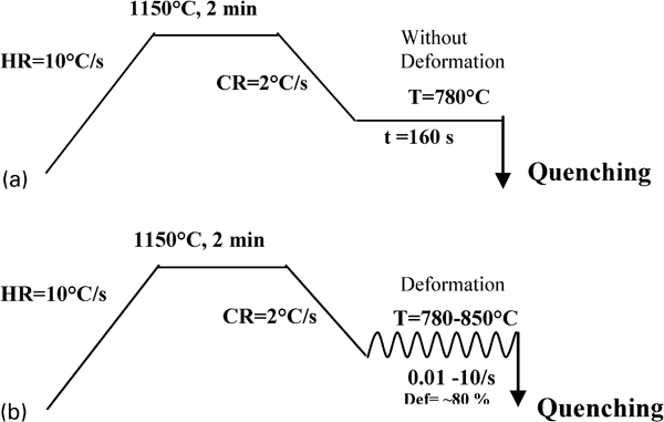
Schematic diagram of thermomechanical cycle applied on Gleeble-1500 during experimentation
Subsequently, laboratory scale rolling was conducted in an experimental rolling mill in two different ways. In the first rolling (rolling A), the forged samples (40 mm thick) were reheated to 1150°C and then rolled to a 12 mm plate followed by air cooling. This plate was again reheated to 900°C and then rolled with a maximum possible strain of 1·3 in one pass with a finish rolling temperature of just above Ar3. The rolling was performed at a slow speed to achieve a slow strain rate. To compare the properties, the steel was also rolled at a higher temperature of >850°C with a strain of 0·33 like conventional process (rolling B).
Hot rolled samples in both ways were tested for tensile properties in longitudinal direction. Optical and scanning electron microscopy studies were conducted to evaluate the microstructural phases and grain size. Electron backscattered diffraction (EBSD) was used to evaluate misorientation distribution. In order to obtain a dual phase structure, the hot rolled samples were heated to a temperature of 780°C (above Ac1) and soaked for 15 min and then quenched in water. The tensile properties and microstructure was evaluated and compared with those of rolled materials.
Results
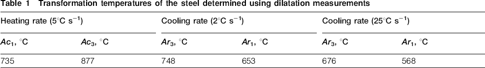
The dilatation curves revealing transformation during heating at 5°C s−1 and during cooling at two cooling rates, 2 and 25°C s−1, are shown in Fig. 2. The transformation temperatures of the steel determined from these dilatation curves are shown in Table 1. Ac1 and Ac3 temperatures were found to be 735 and 877°C, whereas Ar3 and Ar1 temperatures at 2°C s−1 were found to be 748 and 653°C respectively. At a higher cooling rate of 25°C s−1, the transformation temperatures were found to be much lower (Ar3 = 676°C and Ar1 = 568°C). Optical microstructures of the sample cooled at 2 and 25°C s−1 for these steels are shown in Fig. 3. In the case of the cooling rate of 2°C s−1, the microstructure is ferrite–pearlite, whereas specimens cooled at a rate of 25°C s−1 shows a bainitic microstructure. The microstructure of the sample after quenching (cycle shown in Fig. 1a) is shown in Fig. 4, which reveals a fully martensitic coarse microstructure.
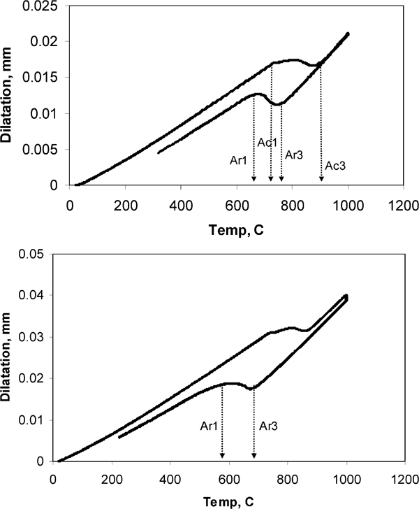
Dilatation behaviour revealing transformation temperature during heating at rate of 5°C s−1 and cooling at rate of a 2°C s−1 and b 25°C s−1
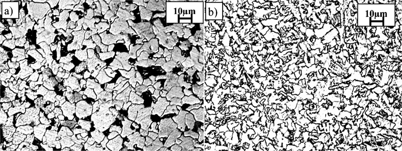
Microstructure of steels cooled at rate of a 2°C s−1 and b 25°C s−1.
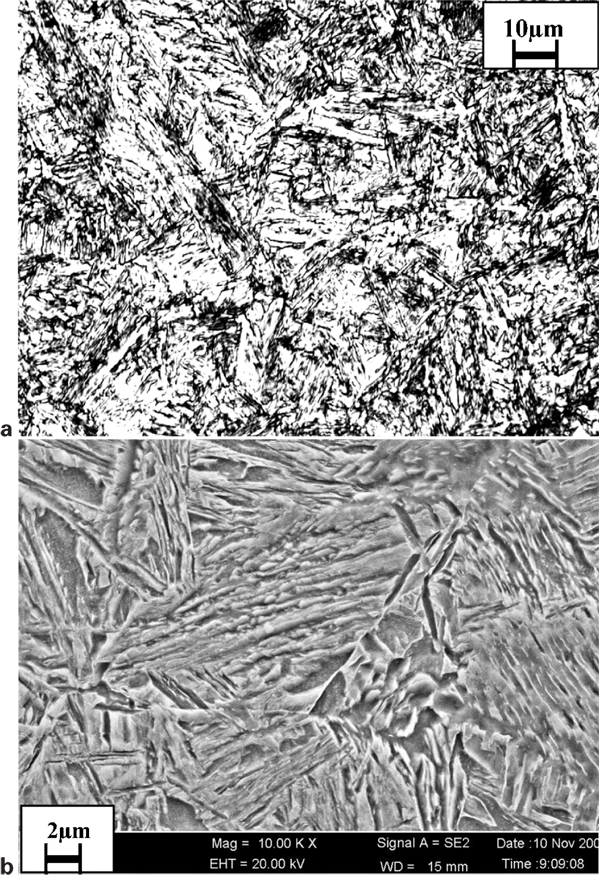
a optical and b SEM microstructures of steel after quenching in water without deformation
Transformation temperatures of the steel determined using dilatation measurements
Hardness plot as a function of temperature of deformation in the centre of cross-section is shown in Fig. 5. Hardness values are almost the same for Td temperature of deformation = 780 and 800°C, whereas at a higher Td of 850°C, the hardness increased. Variation in strain rate did not show any trend on the hardness of steel. A plot of hardness as a function of distance from the centre to the surface is shown in Fig. 6. It showed a much higher hardness on the surface than that at the centre.
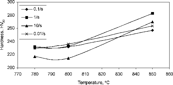
Hardness at centre of steel after thermomechanical treatment with varying temperatures and different strain rates
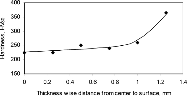
Hardness variation from centre to surface after quenching
Optical microstructures for samples quenched after deformation at various temperatures for strain rates of 10 and 1 s−1 are shown in Fig. 7, whereas those for 0·1 and 0·01 s−1 are shown in Fig. 8. It reveals a very fine microstructure predominantly dominated with low temperature phases in all cases. The SEM microstructures for 0·1 and 0·01 s−1 are shown in Fig. 9. These figures reveal predominantly martensitic microstructure with varying amounts of fine ferrite phase. The amount of ferrite varies with Td and strain rate. A maximum amount of ferrite was found to be ∼50% for Td = 780°C and 0·01 s−1 with grain size between 1 and 4 μm. Grain size distributions for Td = 780°C at 0·1 and 0·01 s−1 strain rates are shown in Fig. 10. In the case of the strain rate of 0·01 s−1, it reveals an average ferritic grain size of 2·7 μm with grain size distribution of ∼30% with <2 μm, ∼70% with <3 μm and ∼95% with <4 μm. At a higher strain rate, a lower amount of ferrite around 20% was noted; however, the average grain size of ferrite was found to be very fine (<2 μm). Misorientation distribution evaluated from EBSD is shown in Fig. 11, which reveals dominance of high angle boundaries.
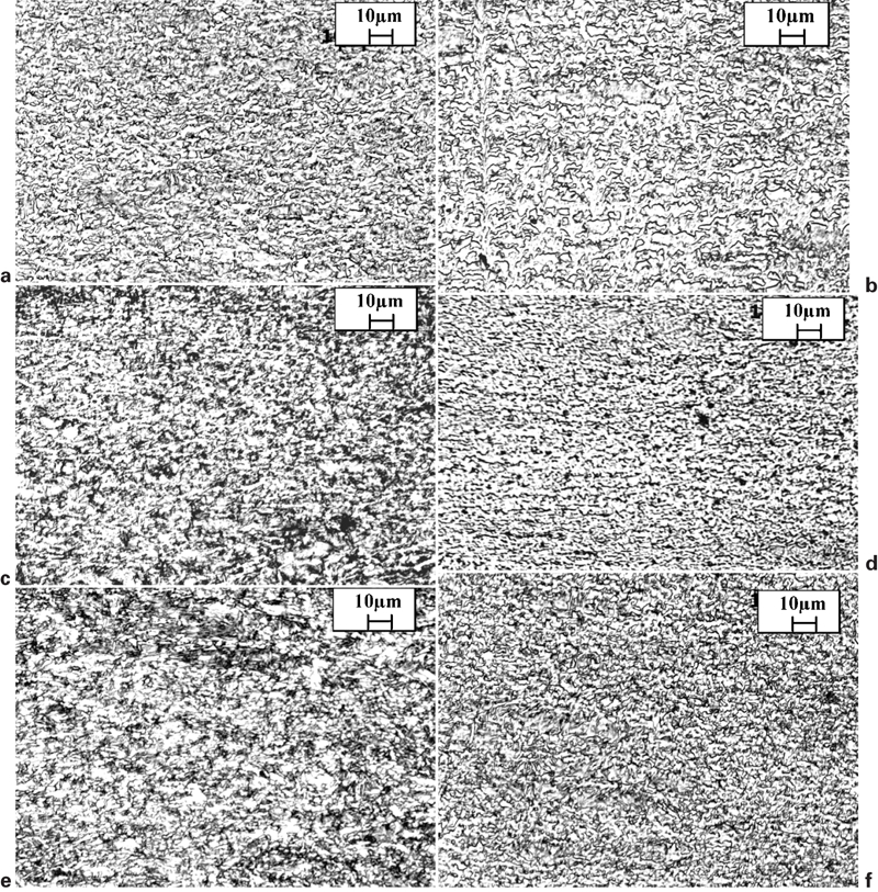
Optical microstructure after thermomechanical simulation (deformed at stain rates of 10 and 1 s−1 followed by quenching at different temperatures)
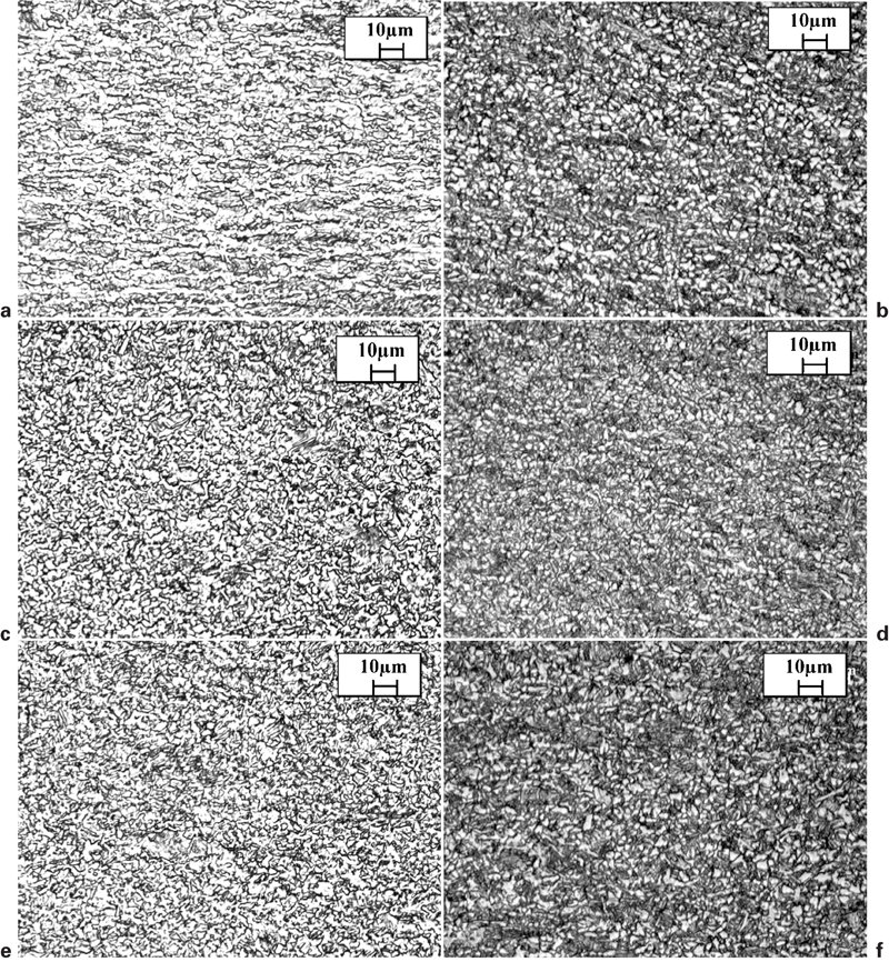
Optical microstructure after thermomechanical simulation (deformed at stain rates of 0·1 and 0·01 s−1 followed by quenching at different temperatures)
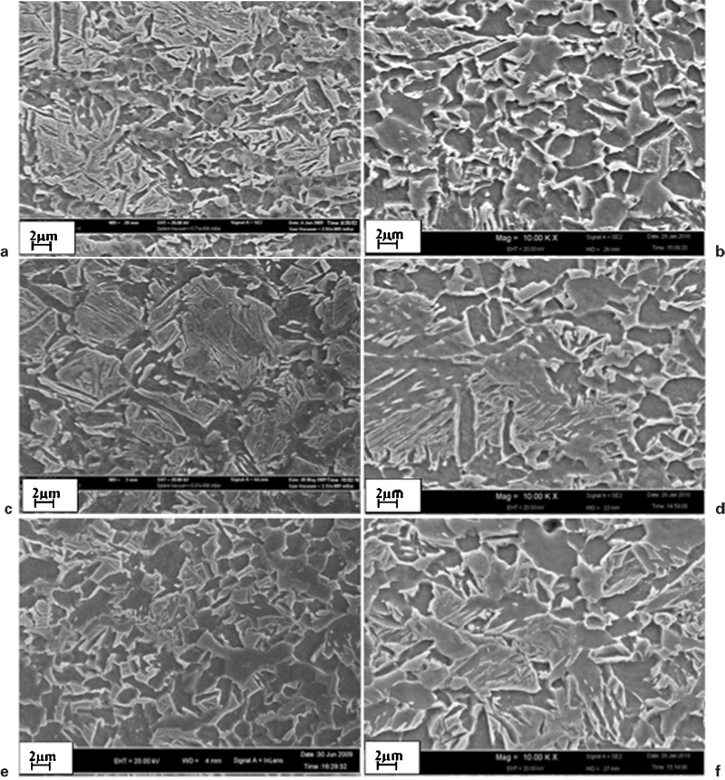
Scanning electron microstructure after thermomechanical simulation (deformed at stain rate of 0·1 and 0·01 s−1 followed by quenching at different temperatures)
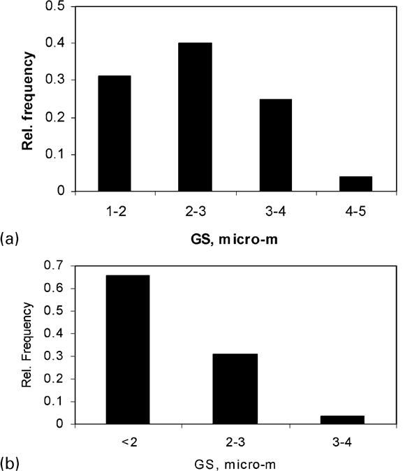
Grain size distribution of ferrite as estimated using SEM

Misorientation distribution of bcc phase determined using EBSD for Td = 780°C and strain rate = 0·1 s−1
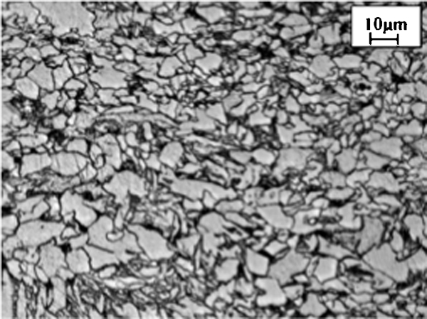
In the case of experimental rolling A (at a high strain of ϵ = 1·3 and a finish rolling temperature to just above Ar3, ∼750°C), the optical and SEM microstructures of the steel rolled are shown in Fig. 12. It shows a mixture of very fine ferrite with some coarse elongated pancake ferrite–pearlite microstructure. The distribution of grain size is shown in Fig. 13. The average grain size of the ferrite was ∼2 μm as against the coarser ferrite–pearlite microstructure with higher grain size for convention rolling shown in Fig. 14 (rolling B). The tensile properties of the steel are compared in Table 2. The steel in the case of rolling A results in much higher strength than that of conventional rolling. However, the elongation and n values were found to be lower. After intercritical annealing at 780°C for 15 min, optical and SEM microstructures are shown in Fig. 15, which shows a two-phase microstructure, i.e. ferrite with ∼20% martensite similar to a typical dual phase steel. The result showed very high tensile strength with low yield strength/ultimate tensile strength (YS/UTS) ratio, high elongation and high n values. The tensile properties of the steel are included in Table 2. The result showed very high tensile strength with a low YS/UTS ratio, high elongation and high n values.
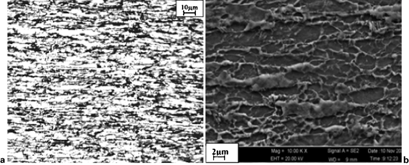
a optical and b SEM microstructures of rolled steel sheet (rolling A)
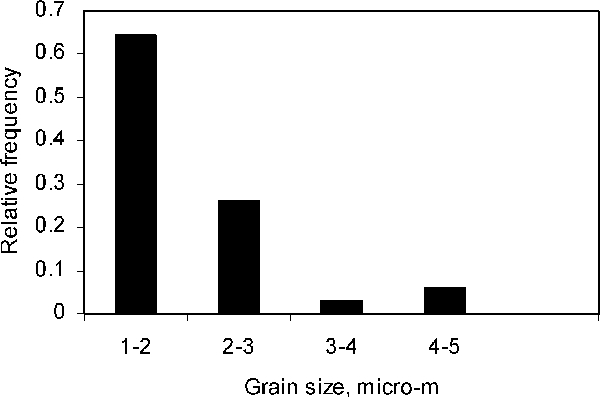
Grain size distribution of ferrite as estimated using SEM for rolled steel sheet (rolling A)
Optical microstructures of steel sheet after conventional rolling (rolling B)
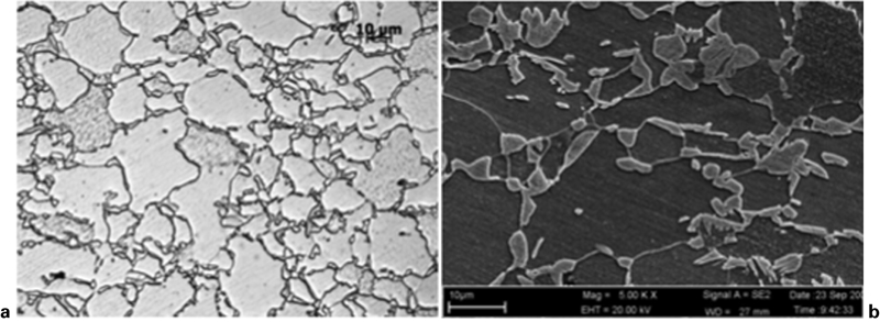
a optical and b SEM microstructures of steel sheet after intercritical annealing (780°C/15 min) showing dual phase microstructure
Mechanical properties of steel rolled in experimental rolling mill and heat treated intercritical range*
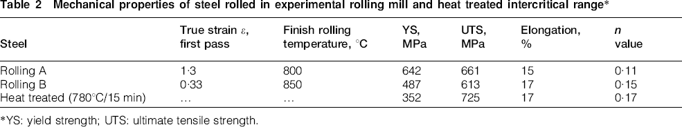
*YS: yield strength; UTS: ultimate tensile strength.
Discussion
The purpose of adding microalloying elements to these steels was to have a finer austenite grain size before thermomechanical treatment, which may be beneficial in achieving an ultrafine grain structure after heavy deformation. The effect of γ-grain size on the grain size during deformation induced ferrite formation has been reported by Choi et al.4 and showed that a finer grain size led to a finer ferritic grain size. The solubility of microalloying elements was assessed using Thermo-Calc and is shown in Fig. 16. The dissolution temperature of Nb in this steel was estimated to be ∼1140°C as compared to a very low temperature of V. V was found to dissolve even at a very low temperature of 800°C. Ti precipitate being a very stable compound dissolves at a very high temperature. At a reheating temperature of 1150°C in the present experiments, it is expected to dissolve all Nb and V precipitates in austenite and precipitate during subsequent thermomechanical treatment. In the present experiments, cooling up to Ar3, austenite transformation is not expected; however, due to the decrease in solubility, precipitation of fine niobium and vanadium carbides and nitrides will occur, which will assist in the refinement of the grain size.
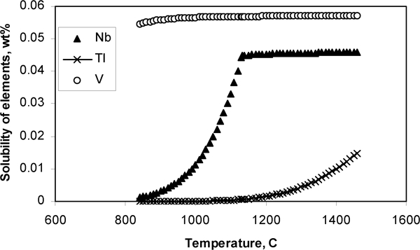
Precipitation behaviour in steel evaluated from Thermo-Calc
To apply heavy deformation above Ar3 temperatures in the thermomechanical cycle employed, the temperatures of deformation Td were decided as 780, 800 and 850°C, which fall in the range of Ar3 and Ac3. After quenching from these temperatures (above Ar3), formation of martensite is expected with a high hardness value. In these experiments, quenching after deformation resulted in varying hardness values (217–275 HV) as against a higher hardness value (280 HV) of the quenched samples without deformation. Lower hardness at lower Td of 780°C as compared to 850°C may be attributed to enhanced ferrite formation during deformation by dynamic transformation. Hardness results also showed good agreement with the microstructures observed. When a sample was quenched without deformation from 780°C following the similar cycle, the microstructure was observed to be fully martensite (Fig. 4), and it also revealed a higher value of hardness. However, when deformation was applied before quenching, some amount of softer phase formed, leading to a lower hardness value. The difference in the microstructure may be attributed to the variation in Td and strain rate. The lower hardness appearing for lower Td was found to be due to some amount of ferrite formation. When the hardness was measured across the cross-section, the hardness on the surface was at maximum, and at the centre, it was minimum. Variation in hardness from the surface to the centre is as expected, since during compression, the strain varies from the surface to the centre. The strain at the surface is minimum, and maximum at the centre. This is one of the evidence of ferrite formation at the centre when the strain is high.
A maximum amount of ∼50% ferrite formation was noted for Td = 780°C at a strain rate of 0·01 s−1. The grain size measured using SEM (Fig. 5) was found to be ultrafine of the order of 2·5 μm. It means that during deformation itself, some amount of austenite transformed to ultrafine ferrite. After quenching, the remaining austenite transformed to martensite, leading to a final ferritic–martensitic microstructure. The formation of ultrafine grained ferrite during heavy deformation has been reported by many earlier researchers.3–14 This phenomenon is termed as strain induced dynamic transformation or deformation induced ferrite transformation. In the present case, Ar3 temperature of this steel at 2°C s−1 is 745°C, and a maximum amount of ultrafine ferrite formed at 780°C at a strain rate of 0·01 s−1. Thus, it is clear that ferrite formation is favoured when deformation is applied closely above Ar3 at a slower strain rate. The mechanism for ultrafine ferrite formation is described earlier.4 Heavy deformation at a low temperature yields in a high amount of dislocation density, deformation bands and defects, leading to more nucleation sites for transformation. In the case of ultrafine grain, dominance of high angle boundaries was observed, and it is in agreement with the earlier investigators. 4 4,5 High nucleation rate and random orientation distribution are the governing factors for achieving ultrafine grain size. At a higher strain rate (i.e. 10 s−1), the deformation time is very short (∼1·6 s for ϵ = 1·6), which may be insufficient for ferrite formation. From these experiments, it is also clear that, with a deformation of ∼80% (ϵ = 1·6) even at a very slow strain rate, a limited amount of ultrafine ferrite forms. To achieve a higher amount of ferrite, it would be necessary to apply a higher amount of strain, which was not possible in the present apparatus. In dual phase steel, the amount of ferrite required is 80%, and to achieve this, a very high amount of deformation will be necessary. Figure 17 depicts stress–strain behaviours during hot deformation as a function of time for different strain rates at Td = 780°C. It is clear that the rolling load increases with the increase in time in a similar fashion at all strain rates. However, at a strain rate of 0·01 s−1, a lower stress was observed, clearly indicating the formation of some softer phases restricting the load increase.
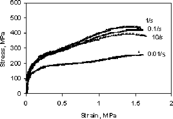
Flow stress as function of strain during compression test at varying strain rates for Td = 780°C
To explore the possibility of producing fine grained ferrite during rolling, the forged plate of this steel was hot rolled in the experimental rolling mill with a maximum possible deformation (ϵ = 1·3) at a finish rolling temperature to just above Ar3. In this rolling, a part of the transformation occurred dynamically during deformation, leading to an ultrafine grain size. Further transformation below Ar3 led to the formation of a coarser structure. This is why the microstructure revealed a mixed distribution. The steel rolled in this way resulted in a much higher YS and UTS than those of a conventionally rolled material due to a large fraction of ultrafine finer grain size. However, the elongation and the strain hardening exponent decreased. Lower elongation in the case of ultrafine steel is reported by many researchers, and the present results are in agreement with them.16 An attempt was made to produce conventional dual phase structure for comparison with the properties of ultrafine grained steels. The heat treated steel in intercritical range showed a two-phase microstructure, i.e. ferrite with ∼20% martensite. The result showed very high tensile strength with a low YS/UTS ratio, high elongation and high n values. These properties are superior to that of ultrafine grained steel for forming application. However, due to a very high YS obtained for the ultrafine grained steel, it would be very useful in many non-forming and direct applications.
Conclusions
A high amount of deformation closely above Ar3 led to ultrafine grain ferrite formation. Deformation induced ferrite formation was found to be favourable at a lower temperature, i.e. closer to Ar3, at a slow strain rate. Around 80% deformation at a strain rate of 0·01 s−1 resulted in ∼50% ferrite with an average grain size of the order of 2·7 μm. Hot rolling just above Ar3 at a slow speed followed by air cooling showed a mixed grain distribution. Predominantly fine grain of the order of 2–3 μm was observed with some amount of coarser grained ferrite pearlite of 4–5 μm as against a coarser microstructure of a conventionally rolled steel. The properties of the steel rolled with ultrafine grain size showed much higher strength with deterioration in elongation and strain hardening exponent values restricting its uses in critical forming application.
Footnotes
Acknowledgements
The authors are grateful to Tata Steel Ltd for the permission to publish the present paper. They would also like to thank Dr Anil Kumar Verma, Mr Vikram Sharma, Mrs Vijaya Lakshmi and Mr Mohit Kumar Lal for their assistance in conducting laboratory experiments.