
Abstract
Top blow injection of a gas–solid jet through a circular lance is used in the Mitsubishi continuous smelting process. One of the problems associated with such injection is the severe erosion of the hearth refractory below the lances. A new configuration of the lance to form an annular gas–solid jet rather than the circular jet was designed in this laboratory. With this new configuration, solid particles, fed through the centre tube, leave the lance at a much lower velocity than the gas, and the penetration behaviour of jet is significantly different than that of circular lance where the solid particles leave the lance at the same high velocity as the gas. In an earlier cold model investigation, the effects of gas velocity, solid feedrate and lance height of the annular lance were studied and compared to the circular lance. This paper reports on experimental work that includes the effects of the size of the annular lance, which greatly expands the applicable range of the developed correlation. It has been shown that the variation in penetration depth with the annular jet cross‐sectional area depends strongly on the mass loading of the solid particles. A correlation equation for the penetration depth that shows a good agreement with the measured values has been developed.
List of symbols
diameter of lance
diameter of a circle with the same cross‐sectional area as the annulus area
axial distance from lance tip
axial distance from lance tip to rest surface of liquid bath
penetration depth
gravitational acceleration
jet constant for centreline velocity, defined in equations (1) and (2)

momentum rate

mass flowrate
radius of the curvature at the bottom of the cavity
Reynolds number ( = ρDUo/μ)
volumetric flowrate
velocity
viscosity
spreading angle of jet
density
surface tension
Subscripts
centreline quantity
gas property
liquid property
quantity at lance tip
particle property or penetration
Introduction
The Mitsubishi process is a copper smelting and converting process capable of continuously producing blister copper from copper concentrates.1– 4 This process employs matte smelting, slag cleaning and converting furnaces connected in series by a continuous gravity flow of molten materials through heated and covered launders. In the smelting and converting furnaces, top blow vertical lances are used to feed raw materials, fluxes and oxygen enriched air into a molten bath. The deep penetration and strong agitation provide a good contact among oxygen, liquid and solid particles, resulting in rapid heat and mass transfer and high production efficiency.5, 6
On the other hand, excessively deep penetration of the gas–solid jet causes serious wear of the refractory beneath the lances.1, 7– 9 In the late 1970s, Mitsubishi Materials Corporation1, 8 studied the behaviour of gas–solid jets injected from a circular lance into a liquid bath to avoid sudden melt leakages from the smelting furnace due to rapid erosion of the hearth brick that they had experienced. The results of their study were applied to an improved design of the smelting furnace and lances to reduce the wear of the hearth bricks, to maintain a deeper bath, to set a proper distance between the lance tip and the bath surface and to enlarge the diameter of the lances for a reduced jet velocity.8 However, in spite of many improvements, the replacement of worn refractory on the hearth of the smelting furnace continues to cause costly shutdowns in the Mitsubishi process.7– 9
In addition, the existing lance system requires the solid charge to be under a pressurised gas to make a gas–solid jet at the intake of the lance pipe. Thus, it is necessary to transport the solid charge by high pressure pneumatic conveyors rather than simple drag or screw conveyors. The pneumatic conveying system causes frequent leakage in the conveying pipe due to erosion by abrasive solid particles and requires frequent and expensive repairs.
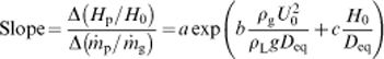
The current lances are designed to form a gas–solid mixture at the top end so that solid particles leave the lances at the same high velocity as the gas.1 If the solid particles are separated from the gas stream inside the lance and exit the lance at a lower velocity than the gas, the penetration behaviour of the jet in liquid would be significantly different. In the annular lance configuration, the inner pipe is extended all the way down to the tip of the outer pipe, which leads to the feeding of solid particles into the lance by gravity. In such a case, particles will exit the lance with a lower velocity than the gas. Figure 1 schematically shows the difference in the configurations of the existing Mitsubishi lance and an annular lance.
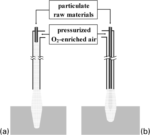
Configurations of lances
This paper reports on experimental work that includes the effects of the size of the annular lance, which greatly expands the applicable range of the developed correlation. It will be shown that the variation in penetration depth with the annular jet cross‐sectional area depends strongly on the mass loading of the solid particles. The effects of the annular cross‐sectional area as well as those of gas velocity, solid feedrate and lance height on the penetration depth of an annular gas–solid jet were investigated. The results were correlated by an equation describing the penetration depth of an annular gas–solid jet into liquid as a function of experimental conditions.
Review of previous work
Characteristics of turbulent free gas jets
Figure 2 depicts a typical shape of a free turbulent gas jet (Re>2500).10, 11 In the region of the established flow (7<H/Do<100), the total mass flowrate increases, and the velocity decreases. The decay of the centreline velocity Uc with axial distance H is expressed by12

Parameters relevant to impinging gas jet
For an annular jet, the centreline velocity profile is given by the same equation (equation (1)) with D0 replaced by Deq, the diameter of a circle with the same cross‐sectional area as the annulus area.13, 14 The expression is

Impingement of gas jets on liquid baths
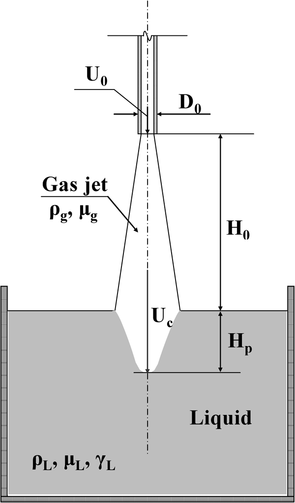
A circular gas jet impinging on a liquid bath depresses the surface and forms a cavity in the liquid. Figure 2 depicts such a cavity, created by a gas jet, leaving a circular nozzle at a velocity Uo.
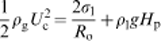
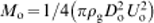
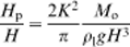
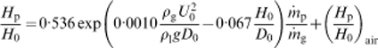
The depth at the centre of the cavity Hp can be analytically determined from the consideration that the momentum of the jet at a distance (H0+Hp) along the centreline is equal to the sum of the surface tension force and the pressure force at the gas/liquid interface.15– 17 This leads to the following expression
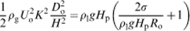
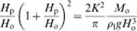
 , the equation becomes in dimensionless form15– 17
A more detailed review of a free jet and the impingement of gas jets on liquid baths can be found in Refs. 19 and 20.
Annular gas–solid jetting into liquid baths
An experimental investigation of the penetration behaviour of an annular gas–solid jet into a liquid bath was performed by Park et al.19, 20 The main goal of their study was to compare the penetration behaviours of annular and circular gas–solid jets impinged normally onto a liquid bath. In Park et al.‘s cold model tests using air, sand particles and water, the experimental variables were sand feedrate, air flowrate and nozzle–water distance. The diameters of the tubes that were used to compose the annular lance were not changed, so that the cross‐sectional area of an air jet was kept constant. The results from Park et al.‘s19, 20 experiments led to the following conclusions:
the penetration depth of an air–sand jet increases linearly with the increase in sand feedrate for both circular and annular lances
the rate of increase in the penetration depth with the sand feedrate increases with the air velocity and decreases with the lance height
the effect of sand feedrate on the penetration depth is much smaller for an annular air–sand jet than for a circular air–sand jet at a given air velocity and lance height
the effect of air linear velocity on the penetration depth is also much smaller for an annular air–sand jet than for a circular air–sand jet at a given sand feedrate and lance height.
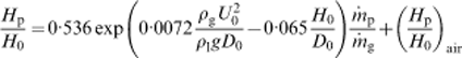
The following correlation equations, developed by Park et al., 19, 20 described the penetration depth very well within the range of experimental conditions: for circular lance
Apparatus and experimental procedure
Apparatus
Figure 3 illustrates the experimental apparatus consisting of a liquid bath, an annular lance, an air chamber, a particle hopper and an air supplying unit. A tank of square cross‐section, resting on a steel frame, was used to hold the water. It was 125 cm high and 81 cm wide in both horizontal directions and was made of transparent acrylic sheets for the visual observation of water depression formed by the impinging jets. An adhesive rule was attached vertically on the wall of the tank to indicate the cavity and penetration depths from the resting water surface. A laser level was utilised to measure the levels of the lance tip, the resting water surface, the bottom position of the cavity and the penetration depth of a gas–solid mixture. A digital camera was used to record the pictures of cavities formed in water. Figure 3 also shows the detailed configuration of the annular lance, composed of the outer and inner pipes. Outer pipes of four different diameters with the same inner pipe were employed to investigate the penetration behaviour of gas–solid jet. The inner and outer pipes were connected to the particle hopper and the air chamber respectively. The tip of the inner pipe was flush with that of the outer pipe, so that the cross‐section became an annulus at the tip of the lance and the sand particles met the air jet right at the exit of the lance pipes. An assembly of pipes was situated so that the air flow and the sand particle feeding were vertically downward and at the tank centreline. The distance between the resting water surface and the tip of the nozzle was altered by changing either the depth of water in the tank or by altering the position of the lance. The sand particles were fed to the inner tube from the hopper by opening a valve. The air chamber had a connection from the side for the compressed air supply to the annulus of the lance. The other air supply line was connected to the top of the particle hopper to apply pressure to vary the sand feedrate. The rotameters in the air supply line measured and controlled the air flowrates. The pressure gauges were used to measure the pressure at the outlets of the rotameters to correct the flowrate readings.
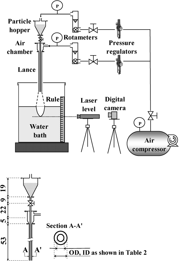
Sketch of experimental apparatus with detailed configuration of annular lance (dimensions in cm)
Materials
Compressed ambient air, sieved sand and tap water were employed for these cold model tests of impinging gas–solid jets onto a liquid bath. Their relevant properties are listed in Table 1.
Properties of materials

*Average atmospheric pressure at Salt Lake City.
Experimental procedure
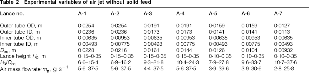
First, the depths of cavities in water were measured at various air flowrates, lance heights and annulus cross‐sectional areas to study the behaviour of an annular air jet. Then, the penetration depth of an air–sand jet was measured at various sand feedrates, air flowrates, lance heights and air jet cross‐sectional areas. The experimental variables for both the air and air–sand jets are given in Tables 2 and 3.
Experimental variables of air jet without solid feed
Experimental variables of air–sand jet
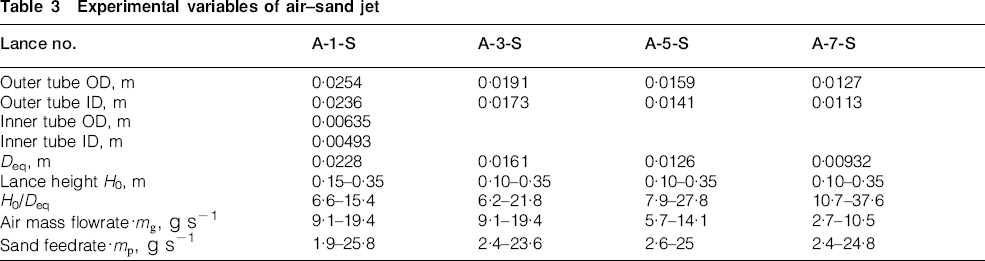
The air flowrate was measured and controlled by the rotameter equipped with a throttle valve in its measuring range from 4 to 40 standard cubic feet per minute (1 standard cubic feet per minute = 28·3 NL min−1). The reading from the rotameter was calibrated with the operating pressure measured at the outlet. The calibrated flowrate gave the mass flowrate and the average axial velocity of a jet at the lance tip. In the case of air jet injection, the annulus cross‐sectional area was changed by varying both the inner and outer tube diameters. When the sand particles were laden on the air jet, only one inner pipe diameter was used because of the difficulty in controlling the feedrate with a smaller or larger diameter of the tube. In this case, the annulus cross‐sectional area was changed by varying the outer tube diameter. The feedrate of solid particles was determined by measuring the weight of the sand particles and the injection time for sand feeding. The pressure in the air line connected to the particle hopper controlled the particle feedrate with a negligible amount of air flow.
Results and Discussion
Behaviour of an air jet without solid particles
The behaviour of an air jet from a circular and an annular lance and the measurement of the penetration depth with an annular lance of a fixed size were describe in detail by Park et al.20 In this work, additional measurements were made by varying the cross‐sectional area of the annulus in the annular lance. The overall correlation equation obtained, including the effect of varying annular area, was almost the same as that of Park et al.20 A careful examination of the data suggested that for an annular lance having a greater area through which the jet flows, the K value was higher. Thus, the jet constant K is related not only to the velocity of the jet but also to the area through which the jet flows. This confirmed that the Reynolds number is the most appropriate term with which to correlate K because it contains both the velocity and the jet diameter. The best correlation for K, obtained using the procedure of Park et al., 20 was found to be21

Behaviour of an air–sand jet
Similarly to the air jet experiments, air jets laden with sand particles from the annular lance were directed normally towards the water bath with varying sand feedrate, air flowrate and lance height. The air–sand jets formed cavities of significantly different shapes. A cavity of a well defined shape as that made by a jet of air was formed only at relatively low mass flowrates of sand particles. In this case, the penetration depth is measured at the deepest point of a cavity. However, at the highest range of sand feedrate and with significant air flowrate, an emulsion of air bubbles mixed with sand particles penetrates deeply into the water bath without forming a well defined cavity. In such a case, the penetration depth of an air–sand jet is recorded as the point where the sand particles separated from the air bubbles and fall down to the bottom of a bath just by gravity.
One of the reasons for the deep penetration of the air–sand jet at a high mass flowrate of sand is the formation of air–water emulsion under the lance area, the average density of which is much smaller than the pure water density. The density of sand particles is much larger than the average density of air–water emulsion, and therefore, the effect of mass feedrate is much higher than that of the flowrate of air at high mass loading of the sand particles. As the sand feedrate increases, the momentum rate of sand becomes dominant over that of the gas. Figure 4, plotted in dimensionless form of Hp/H0 versus
 , shows the variation in the penetration depth of an air–sand jet issuing from lances of various diameters with the feedrate of sand particles at various air jet velocities and lance heights. It was found that the penetration depth increases linearly with the mass flowrate of sand particles. As can also be seen from the plots, the slope of the line increases with air jet linear velocity at the tip of the lance and decreases with lance height.

Variations in penetration depth with sand feedrate at various air jet velocities and lance heights for lance equivalent diameter Deq of a 2·28 cm, b 1·61 cm, c 1·26 cm and d 0·93 cm
The penetration depth was plotted against the linear velocity of air jet issuing from the nozzle of various cross‐sectional areas at several fixed values of the mass loading of sand, as shown in Fig. 5, for lance heights of 0·15, 0·25 and 0·35 m respectively. Because of the difficulty to control the exact feedrate of sand particles in the experiments, the points in these plots at the selected values of sand loading were generated by linear interpolation of the straight lines shown in Fig. 4.
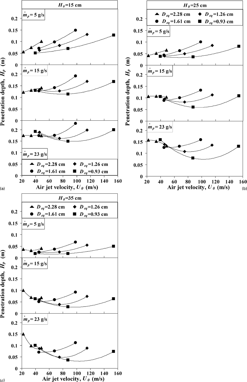
Variations in Hp with outer pipe diameter of annular lance at various velocities and feedrates for lance height of a 0·15 m, b 0·25 m and c 0·35 m
As can be seen from Fig. 5, the tendency of the change in penetration depth with air jet cross‐sectional area is different at low air jet velocities from that at high air jet velocities. Several factors affect the penetration depth of an annular air–sand jet issuing at the same velocity from the outlet of the lance and with fixed sand particle feedrate but with different annulus cross‐sectional area. The first factor is the increase in the mass flowrate of air with cross‐sectional area of the jet at the same velocity. This results in an increase in the total momentum rate of the air jet, and therefore, the penetration depth becomes greater. The second significant factor in the air–sand jetting into a liquid bath that is affected greatly by the cross‐sectional area of the air jet is the spreading of sand particles across the jet. It has been reported by Mitsubishi Corporation1 for a circular lance that as the spreading of solid particles in the jet increases, the contribution of the solid charge to the penetration depth decreases greatly.
As shown in Fig. 5, the penetration depth increases with Deq of the annular lance for sand feedrate of 5 g s−1. The feedrate of sand particles in this case is relatively small compared with the mass flowrate of air. Thus, the air–sand jet behaves similar to a simple air jet without solid feed. When the cross‐sectional area of the lance is increased, the total momentum rate of the air jet increased linearly at the same issuing velocity, and therefore, the penetration depth becomes deeper. However, when a substantial amount of solid particles is present in the jet, the penetration depth behaviour changes greatly, as seen in Fig. 5a, with feedrate of sand particles of 15 and 23 g s−1 and air jet issuing velocities lower than approximately 45–60 m s−1. It can be seen that the penetration depth does not necessarily increase monotonically with the increase in volumetric flowrate. At these low air velocities, the relative contribution of the momentum of the solid particles is high especially at high solid loading, and thus, the increased spreading of particles with increasing air velocity causes a decrease in the penetration depth. At higher air velocities, the momentum of the air jet becomes important, and its increase with air velocity increases the penetration depth more than the increase in solid particle spreading decreases it. Figure 6 shows qualitatively this penetration behaviour of an annular air–sand jet with low and high feedrates of sand relative to the mass flowrate of air at the same linear velocity and how the change in the degree of spreading of the particles affects the penetration depth.
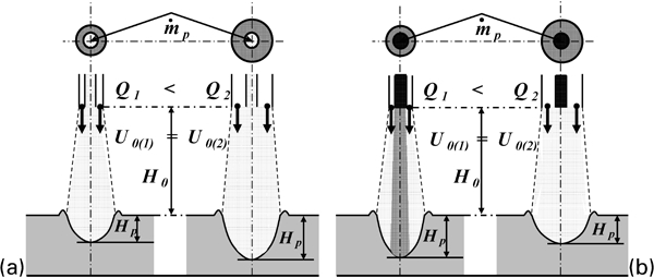
Comparison of penetration depths of air–sand jets issuing at same outlet linear velocity and sand feedrate from different annular cross‐sectional areas
Therefore, at high mass loading of sand particles, the increase in the spreading of sand particles in the jet with larger cross‐sectional annulus area exerts a greater effect on the penetration depth than the effect of the increase in the mass flowrate. It is also shown in Fig. 5 that as the velocity of air increases, the penetration depth of the air–sand jet issuing from a larger area becomes deeper because the mass loading ratio decreases, and the effect of gas momentum becomes dominant.
Comparing Fig. 5, it is observed that the penetration depth decreases with increased nozzle–water distance. This is expected because the centreline velocity of air jet decreases with the distance, and the solid particles spread wider across the jet.
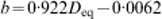
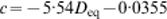
Based on the experimental data, a correlation equation was developed that can be used to estimate the penetration depth within the range of experimental conditions. As was previously shown by Park et al., 19, 20 the slope of the change in penetration depth with the change in the ratio of mass rate of sand particles/air mass flowrate depends on the air jet velocity and lance height as follows

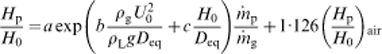
 . The calculated values of Hp/H0 and Hp were compared with the measured values as shown in Figs. 8 and 9.
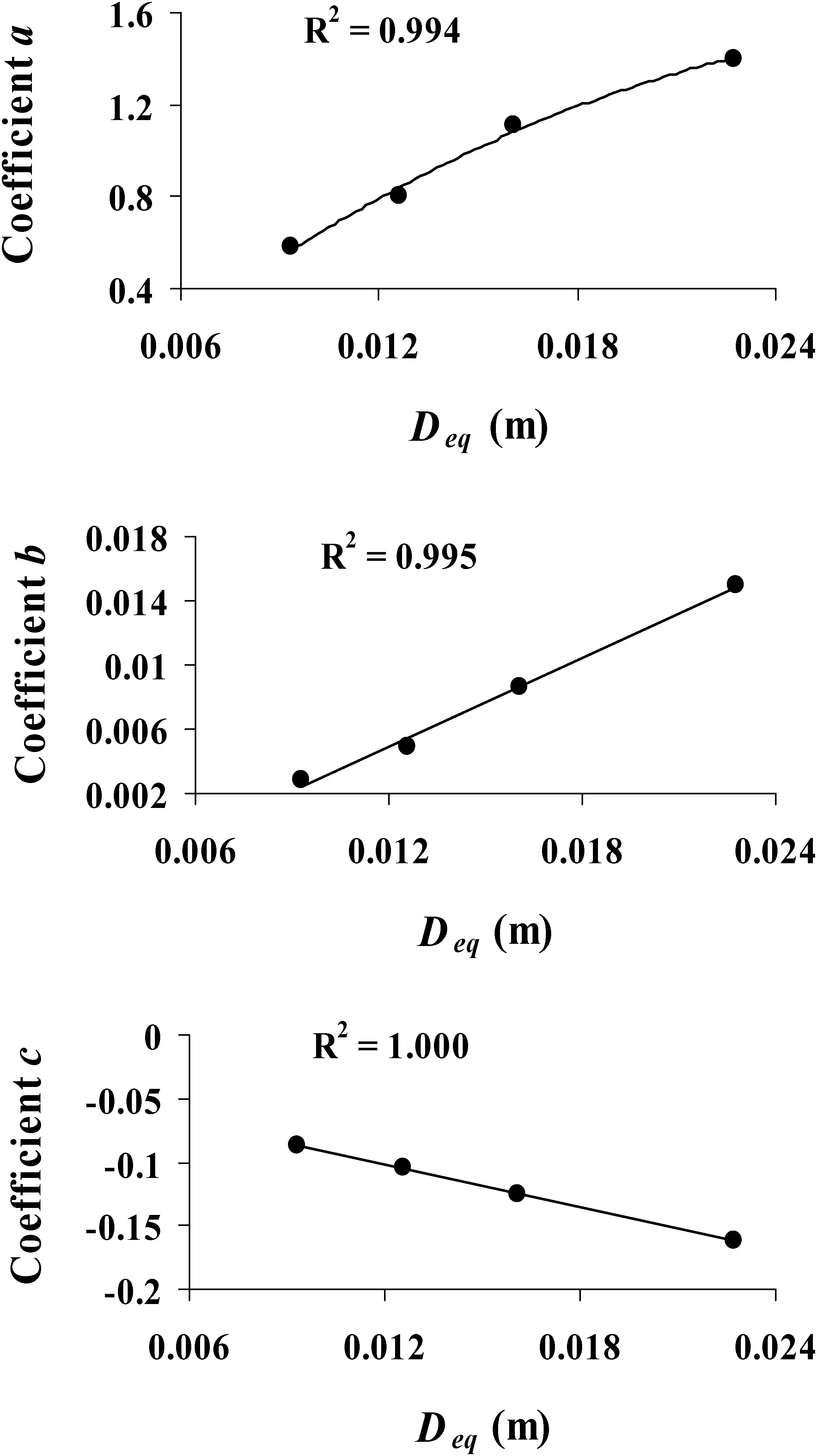
Coefficients a, b and c as functions of equivalent diameter of annular lance
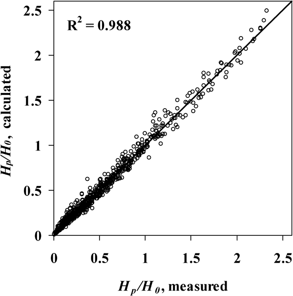
Comparison of calculated dimensionless penetration depths with measured values
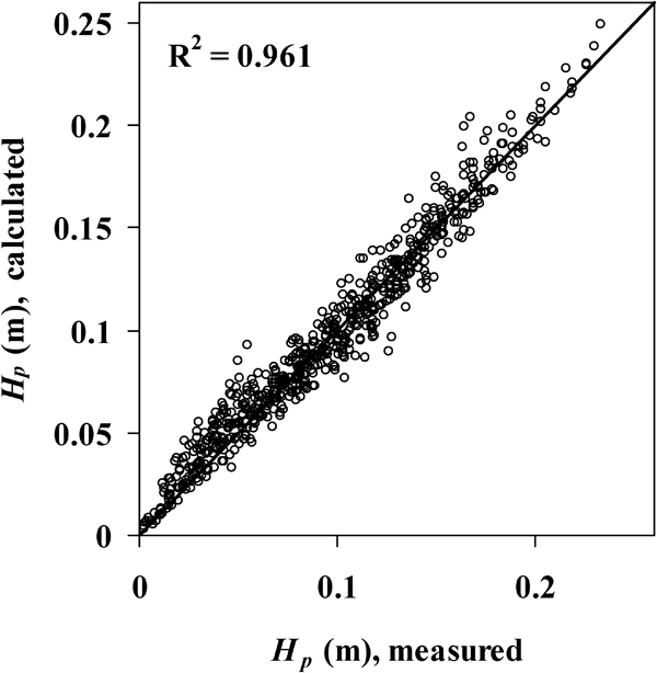
Comparison of calculated penetration depths with measured values
As can be seen from Fig. 9, the correlation equations describe the penetration depth well within the range of experimental conditions. However, some of the calculated penetration depths show larger deviation from the measured values. As can be seen, the calculated penetration depths up to 0·08 m show somewhat larger values than the measured values. It was observed that these values represent the penetration depths for high relative particle loading. It means that the flowrate of air is low in such a case, and therefore, fewer air bubbles entrain into the water. However, as mentioned before, the penetration of an air–sand jet with high sand feedrate is defined at the point where sand particles are separated from air bubbles. Another reason for the deviation is the degree of spreading of sand particles. When the mass loading ratio
 is large at low air mass flowrates, the impinging of solid particles dominates the penetration depth. Therefore, the concentrated presence of particles near the centreline in this situation, which is not accounted for in equation (14), becomes a significant factor.
It is also of interest to examine the effect of cross‐sectional area on the penetration depth of a sand–air jet at a given air flowrate and sand feedrate. In this case, the penetration depth was plotted against the volumetric flowrate of air for lances with various diameters of outer pipe at fixed sand feedrate, as shown in Fig. 10 for lance heights of 0·15, 0·25 and 0·35 m respectively. The points in the figures represent the penetration depths predicted from the consideration of linear relationship of dimensionless penetration depth and the ratio of mass flowrate of sand and air as shown previously in Fig. 4, and the curves represent equation (14) with fixed sand feedrate at various volumetric flowrates of air and lance heights.
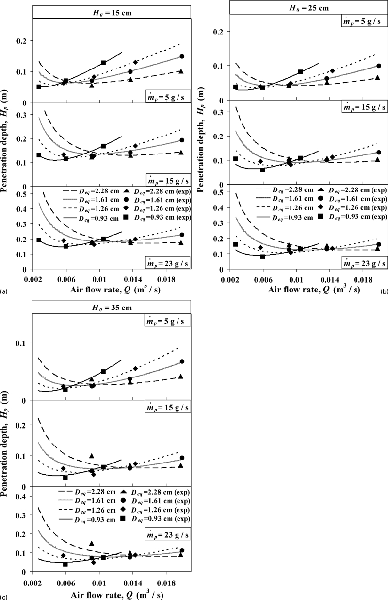
Variations in Hp with outer pipe diameter of annular lance at various flowrates and feedrates for lance height of a 0·15 m, b 0·25 m and c 0·35 m
As can be seen from Fig. 10, the tendency of the change in penetration depth with the air jet cross‐sectional area is completely different at low flowrates of air from that at high flowrates. The decreasing linear velocity of the jet with increasing equivalent diameter of the annular lance at the same volumetric air flowrate results in a decrease in total momentum of the jet. This in turn has an effect of decreasing the penetration depth. However, the variation in particle spreading with annular area is more complicated and affects the overall penetration behaviour differently in low and high ranges of volumetric flowrate of air.
As can be seen in Fig. 10a for sand feedrate of 5 g s−1, at the region of air flowrate higher than 0·006 m3 s−1 or where
 , the penetration depth increases with a smaller cross‐sectional area of an air jet. In this case, the amount of sand particles is small, and therefore, the momentum rate of air is dominant over that of sand. Thus, this case can be easily explained by considering a simple air jetting as described in the previous section. When the air jet issues from a smaller annulus cross‐sectional area at the same flowrate, the linear velocity of the jet is larger and results in a deeper penetration depth. However, in the region of lower air flowrates,
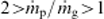 , the penetration depth is shallower for the jet issuing from the lance with smaller cross‐sectional area, as seen in Fig. 10 with different sand feedrates. In such a case, the contribution of sand particles to the penetration depth is dominant, and therefore, the degree of spreading is the more important parameter affecting the penetration depth behaviour. The spreading of particles increases with the gas velocity, and thus, the penetration depth will decrease with increasing gas velocity in this case. Mitsubishi Materials Corporation1 also reported that as the linear velocity of gas increased in a circular lance, the concentration of particles near the centreline decreased. It is of interest to note that in this range of conditions, this effect is much larger than the sum of the effects of the decreased jet cross‐sectional area, which confines the solid particles in a smaller area, and an increase in the linear velocity of air jet, both of which lead to a deeper penetration depth. Figure 11 shows qualitatively the penetration behaviour of an annular air–sand jet with low and high feedrates of sand relative to the mass flowrate of air and the effect of the degree of spreading of sand particles at the same air flowrate.
Comparison of penetration depths of air–sand jets issuing at same flowrate and sand feedrate from different annular cross‐sectional areas
As shown in Fig. 10a, the transition between two opposite behaviours of penetration depth with respect to the air jet cross‐sectional area occurs at higher air flowrates for the case with larger sand feedrate because larger flowrate is required for the air jet momentum to be dominant over the sand particle momentum.
Comparing the plots in Fig. 10 at different lance heights, the effect of nozzle–water distance can be determined. As can be seen, the penetration depth decreases with increased lance height due to the decreased centreline velocity of air jet at the surface of water and the increasing degree of solid spreading. It is also seen that as the lance height increases, the flowrate of air at which the transition between different behaviours takes place increases because of the decrease in the momentum of the gas jet and thus its relative importance compared with the effect of solid particles.
Conclusions
The results from the cold model tests for the penetration behaviour of a gas–solid jet lead to the following conclusions.
The penetration depth increases linearly with the mass flowrate of sand particles. The rate of increase in the penetration depth with the sand feedrate increases with increased air velocity and decreased lance height.
The variation in penetration depth with the annulus cross‐sectional area of a gas–solid jet depends mainly on the mass loading ratio of sand particles relative to gas mass.
At a high mass flowrate of air and a low sand feedrate, the total momentum of air jet is dominant over the momentum rate of sand particles. Therefore, as the cross‐sectional area of the air jet increased at the same issuing velocity, the momentum rate of the air increases, resulting in a deeper penetration depth. In the case when the volumetric flowrate of air is the same, the penetration depth decreases with increasing cross‐sectional area because of the decrease in the jet velocity.
However, when a substantial amount of solid particles is present in the jet, the variation in penetration depth with air jet cross‐sectional area is completely different. The tendency of the penetration depth to increase with annulus cross‐sectional area at the same linear velocity of the jet can be overshadowed by the contribution of the solid particles. When the annulus cross‐sectional area is increased, the degree of spreading of particles increases, leading to a shallower penetration depth even with the increased mass flowrate of the gas.
When the air jet issues at the same volumetric flowrate, the penetration depth can be shallower for a smaller cross‐sectional area despite the higher gas velocity if the mass loading ratio is high. In this case, the effect of the increase in the spreading of sand particles at a higher gas velocity is much larger than the sum of the effects of the decreased cross‐sectional area of the jet, which confines the solid particles in a smaller area, and the increase in the linear velocity of air jet.
It is also noted that the penetration depth decreases with increased lance tip height not only due to a decrease in the centreline velocity at the surface of water but also because of the increase in the particle spreading. The spreading of solid particles is one of the important parameters in gas–solid jetting that affect the penetration depth.
This work that includes the effects of the size of the annular lance greatly expands the applicable range of the developed correlation. It has been shown that the variation in penetration depth with the annular jet cross‐sectional area depends strongly on the mass loading of the solid particles. The results of this study are expected to provide a basis for redesigning the lance to improve the service life of a furnace that uses a gas–solid lance.
Footnotes
Acknowledgements
The authors wish to thank LS‐Nikko Copper Inc., Ulsan, Korea for financial support and permission to publish this work. Nurzhan Dyussekenov received a scholarship from the Government of Kazakhstan during the course of his study at the University of Utah, which is acknowledged with gratitude.