
Abstract
Significant amounts of residual stresses are often generated during welding and result in critical degradation of the structural integrity and performance of components. Neutron diffraction has become a well established technique for the determination of residual stresses in welds because of the unique deep penetration, three‐dimensional mapping capability, and volume averaged bulk measurements characteristic of the scattering neutron beam. Friction stir welding has gained prominence in recent years. The authors reviewed a number of neutron diffraction measurements of residual stresses in friction stir welds and highlighted examples addressing how the microstructures and residual stresses are correlated with each other. An example of in situ neutron diffraction measurement result shows the evolution of the residual stresses during welding.
Introduction
Residual stresses are inherently introduced into materials through many thermal, mechanical and thermomechanical processes such as welding, forming and heat treatments.1, 2 Excessive residual stresses are known to degrade the structural integrity and performance of components. Particularly, in welded structures, an abrupt failure is often caused by the combined effect of residual stresses and applied loads. Since the distribution of residual stresses is of practical importance for the post‐weld mechanical properties, precise measurement of the residual stresses in welds has been a long standing task in the field of materials joining.3 There are numerous experimental and theoretical studies of residual stress and its influence on the mechanical properties in welds. Various destructive and non‐destructive methods have been utilised to characterise the residual stresses in welds. Destructive techniques (for example, hole drilling, contour method and indentation technique) require that the specimen is drilled or cut mechanically to measure the strain components.4 Non‐destructive methods (for example, laboratory X‐ray, X‐ray synchrotron and neutron diffraction methods) based mainly on the Bragg diffraction, determine residual stresses from the changes in interplanar spacing (d‐spacing), which measure the expansion or contraction of the lattice planes.5 Thus, the lattice plane acts as a natural strain gage inside materials.
Neutron diffraction has been well established for the measurements of residual stresses in a wide range of engineering components.6– 10 The deep penetration capability of neutrons into most metallic materials makes neutron diffraction a powerful tool for measuring residual stresses through welds. Furthermore, the unique volume averaged bulk measurements characteristic of the scattering beam and the capability to map in three dimensions are well suited for engineering purposes. In this regard, the neutron diffraction measurement method has been gaining importance and is being used for the studies of the residual stresses in various welded materials.11– 23
Key residual stress measurements in welds obtained by neutron diffraction are as follows. In the early 1980s, Allen et al. 11 suggested using high resolution neutron diffraction to measure small changes in d‐spacing to determine the residual stress tensor averaged over a specific volume in a welded component. Krawitz and Winholtz14 then determined that stress free reference standards are required in welding case in order to convert the measured changes in peak position to strain and stress tensors when considering the metallurgical variation in microstructure during welding. In the 1990s, a number of neutron diffraction measurements of residual stresses were performed based on the theoretical background and various experimental results summarised by Withers,10 Albertini et al. 16 and Stone et al. 17 More recently, the time‐of‐flight (TOF) diffraction enabled by pulsed beams from spallation sources has been gaining a lot of attention.8– 10 Whereas the continuous monochromatic beam generated by nuclear reactors measures a representative peak, a pulsed beam allows simultaneous collection of full information on all (hkl) reflections from a specimen. A pulsed beam source provides a variety of useful information in neutron research. For example, the simultaneous observation of multiple peaks is well suited for the studies of changes in phase and texture and in situ deformation behaviour in many polycrystalline materials. Using a spallation neutron source, Carr et al. 21 and Holden et al. 22 observed that intergranular stress, which is the residual stress equilibrating over a number of grain dimensions (known as microstress, type II),18– 20 underlies the long range microscopic residual stress (type I) in several types of welds.
Friction stir welding (FSW) is an innovative material joining process which has the advantages of solid state joining for the fabrication of continuous linear welds without bulk melting.24, 25 The process utilises a specially shaped tool that rotates and traverses a joint line, creating heat that softens a column of material underneath the tool (Fig. 1). The softened material flows around the tool through extensive plastic deformation and is consolidated behind the tool to form a solid state continuous joint. The economical and technological benefits of FSW have been well established for low melting temperature materials.24– 51 Further material processing technology is being explored that will improve properties. Fundamentally, FSW is a severe thermomechanical deformation process; it relies on extensive thermomechanical deformation to form metallurgical bonding. Among key factors contributing to a successful FSW operation are the temperature and stress distributions during the process, particularly those near the rotating tool pin where the material is stirred and bonding is formed.29, 41, 48 Subsequently, considerable changes in the microstructure and mechanical properties including significant amounts of residual stresses are inevitable due to severe thermomechanical deformation by FSW.27, 30, 32, 34 In this regard, a number of studies on residual stresses in FSW, both experimental and analytical based, have been conducted.52– 71
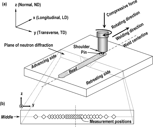
Schematic of a FSW and b spatially resolved neutron diffraction measurement positions across centreline of FSW plate67
Friction stir welding technology has been growing in the past 20 years. The results of residual stress measurements in FSW by neutron diffraction illustrate the potential of the new advanced characterisation method for materials joining science and technology. In this paper, the authors summarise:
theoretical basis and practical issues in the use of neutron diffraction measurements of welds to determine residual stresses (focusing on macroscopic or type I residual stress)
a survey of neutron diffraction measurements on residual stresses in several types of FSWs, including Al alloys, Mg alloys and steels
specific examples for the discussion of the relationship between the welding microstructure and residual stresses in FSW
a novel in situ neutron diffraction experiment which demonstrated the evolution of residual stresses during FSW.
Background
Theoretical basis and strain–stress relationship
The principle of neutron diffraction measurement of residual strains/stresses is based on Bragg's law

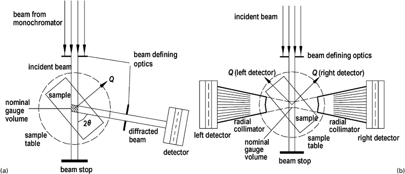
Schematic illustration of a reactor based diffractometer and b spallation neutron source based diffractometer for stress measurements: in both cases strain is measured in direction of scattering vector
There are two types of neutron beams: continuous or pulsed.6–
10 For the continuous beam (the monochromatic beam generated by a nuclear reactor) (Fig. 2a), the wavelength λ is known and fixed. The neutron diffraction measurement gives the d‐spacing dhkl changes as a function of 2θhkl (equation (1)). It is similar to the well known X‐ray diffraction method. The scattering angle of π/2, however, is generally used for neutron diffraction because it gives a cubical gauge volume. As a result, this approach provides a representative (hkl) peak satisfying Bragg's law (Fig. 3a). For the pulsed neutron beam (wavelength sorted white beam from a spallation source), the diffraction angle 2θhkl is fixed and the arrival time t of neutrons at detectors gives λ (t is proportional to λ). Figure 2b shows the TOF technique, which uses the elapsed time t for each neutron travelling from a source to a detector. As a result, the distinct peaks can be measured in a whole range of d‐spacings and separate response of each (hkl) orientation among grains with their plane normal parallel to the diffraction vector
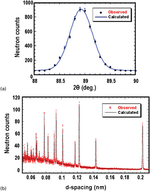
Example of a Bragg peak from reactor based diffractometer fitted with Gaussian distribution and b diffraction spectrum from pulsed spallation source fitted with Rietveld refinements: solid line is calculated result of Rietveld fitting; dots are observed data8
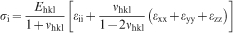
The single (hkl) peak obtained by continuous beam diffractions can be analysed using the least squares Gaussian fitting method (Fig. 3a). For the pulsed neutron beam, the full peak pattern diffracted from the multiple crystallographic lattice planes in a particular material direction is usually analysed by the Rietveld refinement method.72 Rietveld analysis makes use of the entire diffraction pattern by fitting all the diffraction peaks to a structural model of the material. Hence, the Rietveld approach allows accurate determination of d‐spacing with much shorter count times than is typically required for individual peak refinements. Figure 3b shows a typical diffraction spectrum from a pulsed neutron beam instrument and the result of a Rietveld profile analysis.8 The general structure analysis system is a widely used computer program for those analyses.73 Once the d‐spacing is determined, the elastic lattice strain ϵ in a particular direction is calculated in terms of the deviation in the lattice spacing d relative to the unstrained (stress free) lattice spacing do (Refs. 7–10)

Practical issues in neutron diffraction measurements of residual stresses
In the neutron diffraction measurements of residual stresses in welds, it is necessary to first measure the d‐spacings with their scattering vectors parallel to the welding plate's three orthogonal directions [longitudinal direction (LD) (welding direction), transverse direction (TD), and normal direction (ND)] (Fig. 1a),5– 9 which are generally assumed to be the three principal directions of the measured strain tensor in a given linear weld plate. If one uses the instrument in a spallation neutron source, two opposing detectors can measure two d‐spacing components at the same time (Fig. 2b). Then it is necessary to rotate the weld sample 90° relative to the neutron detectors for the measurement of the third component.21, 59, 63 The scattering volume is defined by a pair of incident beam square slit and detector slit, e.g. 2 mm (LD)×2 mm (TD)×2 mm (ND), and provides the volume averaged bulk strain values of the weld. When there is no loss of spatial resolution along the LD in welds, the height of the scattering volume can be enlarged to achieve the higher statistics of the diffraction peak.55, 56, 61 The neutron scattering volume is usually centred on the mid‐plane of welds (Fig. 1b), but it can focus on different locations through the thickness of the weld plate as long as the scattering volume is completely filled within the intended material. It has been shown that the partly filled scattering volume can cause an artifact due to the inappropriate centroid of the sampling gauge and erroneous fitting of the diffraction peaks.8, 9, 74, 75
Second, the unstrained lattice parameter do is required for the standard state as a reference.8, 9, 21, 61, 76 It is used for the determination of residual stresses via neutron diffraction as shown in equation (2). The ‘stress free’ lattice spacing often measured at a coupon taken from the initial base material or a piece of the welded specimen that is far from the process affected zone. In welds a careful determination of do is necessary. Owing to the high temperature and the flow of molten materials during welding, there are significant microstructural changes in the weld metal and heat affected zones.1, 3 The microstructure changes (for example, redistribution of alloying elements) result in corresponding changes in the d‐spacing. Steuwer et al. 77 reported that the pseudo‐strain shift is ∼1000 μϵ due to the solute changes in an AA7010 friction stir weld (Al–Mg–Zn system) (Fig. 4). This is equivalent to a uniaxial stress of ∼70 MPa (corresponding to ∼50% of residual stress). In practice, it is recommended that a few millimetre size cubes be cut from each location of the weld and reassembled to measure the do at corresponding locations of welds (Fig. 5a). It is assumed that the macroscopic stresses are destroyed during cutting the cubes but that the chemistry does not change. A long, rectangular comb‐like sample (Fig. 5b) is also valid for do measurements.76
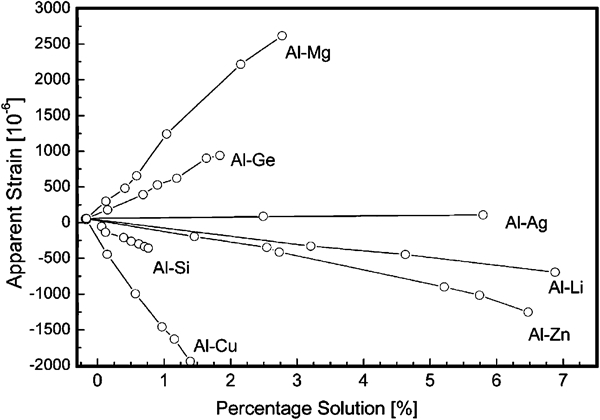
Variation of unstrained lattice parameter do, presented as apparent strain shift with solute content (at‐%) for different solutes in aluminium: both elements Mg and Zn have strong influence on lattice parameter64
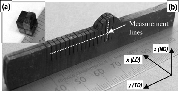
Specimens a set of cuboids and b comb used to find ‘stress free’ parameter do: sample a was assembled from eight small (2×2×2 mm) cuboids; sample b was made from transverse section cut from weld in order to make ‘stress free’ coupon for do measurements76
Consideration should also be given to intergranular anisotropy among grains in welds.2, 9, 10, 22 Intergranular strain is defined as the difference in the strain obtained from a particular (hkl) diffraction peak and the strain due to the plane specific elastic modulus (known as the diffraction elastic constant).18– 20 If there is a significant intergranular strain in a material, a certain (hkl) diffraction peak may not represent the responses for the macroscopic stress field and may only exhibit the response of the specific (hkl) grains. Therefore, when measuring the d and do from the coupons, it is necessary to select the diffraction plane that is not or weakly affected by intergranular strains in order to properly determine the macroscopic residual stresses. The Versailles Project on Advanced Materials and Standards8 procedure recommends the diffraction lattice plane: (111), (311), (422) for fcc Ni, Fe, Cu, Al based alloys and (110), (211) for bcc Fe based alloys.8, 9 In any case, the (200) plane is not recommended due to the large intergranular strains on that plane. Moreover, Ehkl and νhkl in equation (3) need to be used for the ‘diffraction elastic constants’ for the hkl reflection, which can be determined by in situ measurements on a tension sample under loading (see details in Daymond et al.,18 Pang et al. 19 and Clausen et al. 20). Some examples are given below.
Applications of residual stress measurements
Friction stir welding Al alloys
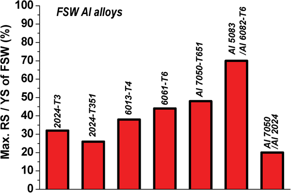
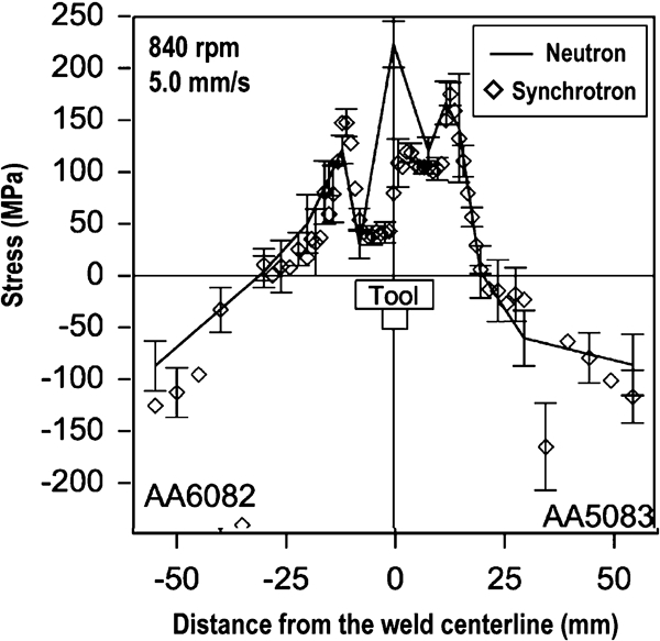
Neutron diffraction measurements of the residual stresses in FSW have been extensively reported (Table 1).52– 71 For the FSW Al alloys, the maximum tensile residual stresses along the welding direction are reported to be about 20–70% of the yield strength of the FSW joint, depending on the welding variables (Fig. 6). Wang et al. 52 and Donne et al. 53 early showed that the strain/stress components have a characteristic peak‐and‐valley shape in FSW Al 6xxx alloys. Sutton et al. 55 used neutron diffraction to construct three‐dimensional maps of the residual stresses along the cross‐section of Al 2024‐T3 FSW plate, as shown in Fig. 7. The maps showed asymmetric distribution of residual stress profiles across the weld centreline and the highest residual stresses developed normally along the longitudinal components in the advancing side of the weld. Staron et al. 56 investigated the influence of an enforced severe cooling on residual stresses in a FSW Al 2024‐T351 alloy joint. Samples were cooled with the CO2 gas along the weld seam during FSW. The results showed tensile residual stresses were significantly decreased near the centre of the weld and that the distance of the maximum residual stress locations became narrower due to the reduced development of the heat affected zone. This work suggests that the heating generated during FSW can be a major source of the residual stresses. Woo et al. 59 clearly deconvoluted the influence of frictional heating and plastic deformation on residual strains generated during FSW (Fig. 8). The comparison between a regular FSW and a modified FSW (subjected mainly to the heating effect) shows that the heat input from the tool shoulder causes significant amount of residual strains.
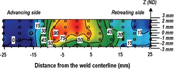
Mapping of longitudinal residual stress through thickness of 7 mm thick FSW Al 2024‐T3 plate prepared at rotational speed of 360 rev min−1 and welding speed of 3·3 mm s−1: maximum tensile stress of ∼105 MPa was observed at 7·5 mm from weld centreline on advancing side of weld and at plate mid‐thickness55
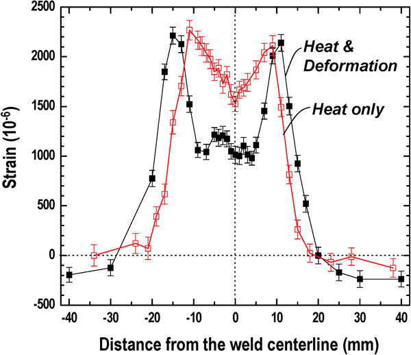
Longitudinal strain profiles in a 6·5 mm thick FSW Al 6061‐T6 alloy plates prepared at a rotating speed of 1250 rev min−1 and a welding speed of 4·7 mm s−1. Strain profiles from the two cases are compared: a typical FSW processed using both stirring pin and tool shoulder (subjected to both heating and deformation); and a simulated FSW using the same welding conditions but utilising a special tool without the pin (subjected mainly to the frictional heating)63
*RS: residual stress; YS: yield strength; UTS: Ultimate tensile strength (MPa).
†Yield strength was obtained from Ref. 25.
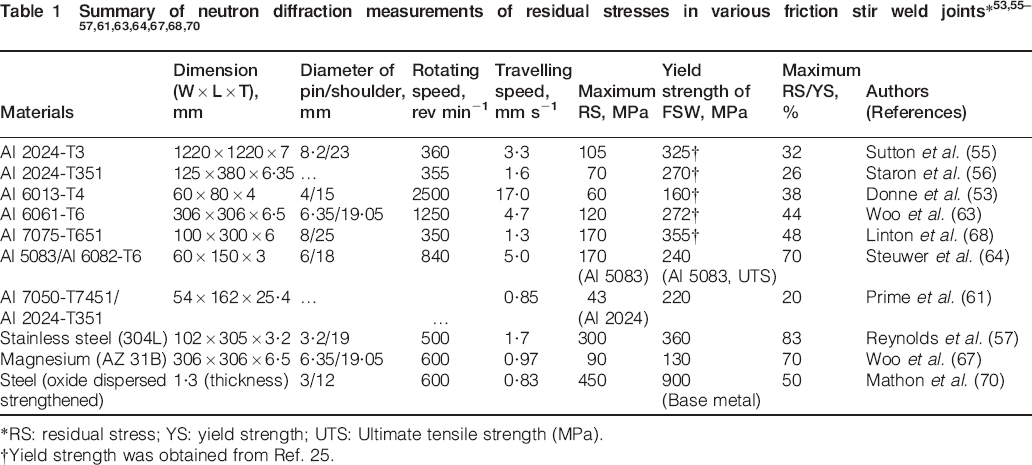
Solid state FSW has the capability of joining dissimilar materials while avoiding many of the difficulties associated with fusion joining techniques.24, 25 Steuwer et al. 64 showed the distribution of residual stresses in an FSW joining two dissimilar alloys: non‐age‐hardening AA5083 and precipitate age‐hardening AA6082‐T6 (Fig. 9). The higher residual stresses of ∼60 MPa were observed in the AA5083 side than AA6082 side of the welds with wider peak profiles much beyond the edge of the tool shoulder. It is attributed to the higher flow stress in non‐age‐hardening AA5083 than that of the precipitate age‐hardening AA6082. It was also concluded that the rotation speed of the tool is a more useful process variable when attempting to reduce the residual stresses of FSW.24, 40 In the age‐hardening Al alloys it has been known that the microhardness changes with time.32, 34, 41, 49 Linton and Ripley68 used neutron diffraction to measure the residual stresses at one week and 14 months after FSW in Al 7075‐T651 alloy. The residual stresses near the weld nugget decreased from about 150 to 50 MPa, whereas those associated with the heat affected zone increased slightly with time.
Longitudinal residual stresses in 3 mm thick dissimilar FSW (AA 5083 and AA 6082‐T6) prepared at rotating speed of 840 rev min−1 and welding speed of 5·0 mm s−1: results measured using synchrotron X‐ray and neutron diffractometers were compared64
Friction stir welding steels
Transportation industries have been aggressively pursuing the use of lightweight alloys and advanced high strength steels for energy efficient vehicles. The FSW process for Al alloys is rapidly developing and successfully implemented into commercial applications, and new efforts are under way to apply FSW to other metals and alloys, such as Mg,38 Ti,42 Cu,43 and steels.31, 37
Reynolds et al. 57 reported an initial neutron diffraction assessment of the residual stress state in FSW 304L stainless steel processed at two different rotation rates (Fig. 10). The maximum longitudinal residual stresses approach 100% of the yield strength (300 MPa) of the base material. The significant residual stress is primarily due to the thermophysical properties of the austenitic stainless steels. Relatively lower thermal diffusivity and higher flow stress at elevated temperature in stainless steel is expected to result in much higher residual stresses compared with those of FSW Al alloy. Zhu and Chao58 simulated the residual stresses in the 304L stainless steel FSW plate processed by the same process variables and sample dimensions as in Reynolds’ work. The results of the thermal numerical simulation and three‐dimensional elastic–plastic thermomechanical modelling confirmed the residual stress data obtained via neutron diffraction. Moreover, it shows that the residual stresses are significantly decreased due to the release of the welded plate constraint after welding.
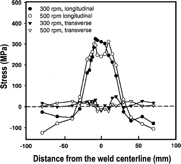
Longitudinal and transverse residual stresses measured from 3·2 mm thick FSW stainless steel 304L: FSW stainless steel specimen were prepared at welding speed of 1·7 mm s−1 and at two different tool rotation speeds (300 and 500 rev min−1) with argon shielding gas and tungsten alloy welding tool57
Recently, Mathon et al. 70 measured the residual stress profiles in 1·3 mm thick oxide dispersed strengthened (oxide dispersed strengthened) steel. The oxide dispersed strengthened steel has the high yield strength of 900 MPa due to the presence of very high density, nanometre scale Y–Ti–O precipitate phases in the matrix acting as a barrier to move dislocations and grain boundaries. The results showed the asymmetric distribution of residual stresses in the sample: more than 450 MPa in the advancing side and only 320 MPa in the retreating side. The transverse residual stress is also high (up to 320 MPa in the advancing side) compared with the longitudinal residual stress in the FSW oxide dispersed strengthened steel.
Friction stir welding Mg alloys
Magnesium alloy is one of the lightest metals used in popular for structural applications. Spatially resolved neutron diffraction measurements of residual stresses have been performed by Woo et al. 67 in FSW AZ31B Mg alloy (Fig. 11a). The result shows a peak‐and‐valley shape that has been typically observed in FSW Al alloys.53, 55, 56, 63 For example, longitudinal residual stress determined by single peak fitting of the (10–11) peak shows compressive stress of − 40 MPa at −60 mm from the weld centreline. It increases to maximum tensile stress (130 MPa) at ±2 mm, and significantly decreases to compressive stress (−10 MPa) at ∼0 mm. Commin et al. 51 reported a similar level of longitudinal tensile residual stress (70–80 MPa at 4 mm from the weld centreline) determined by strain gauge and X‐ray diffraction measurements in a Mg FSW AZ31‐O Mg alloy (2 mm thick hot rolled sheets).
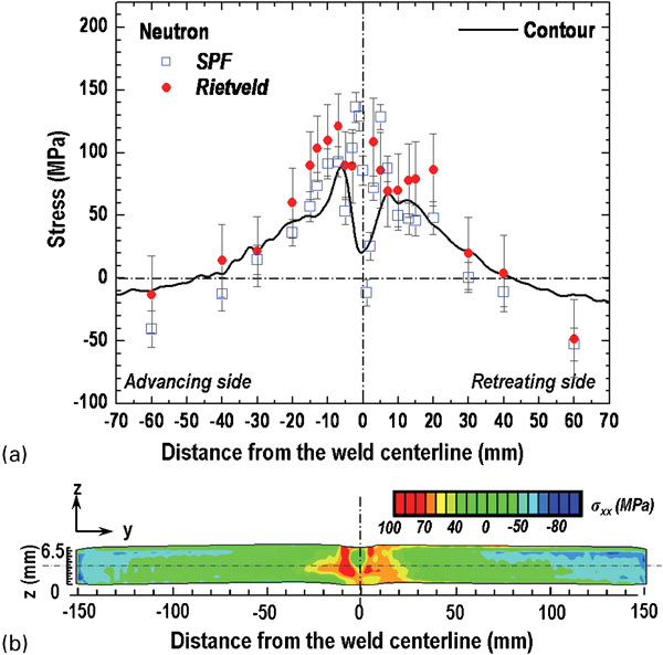
Longitudinal residual stress measurements from 6·5 mm thick FSW AZ31B Mg alloy plate processed at rotating speed of 600 rev min−1 and welding speed of 0·97 mm s−1
The residual stress distributions measured by neutron diffraction are compared with the results of contour method in Fig. 11a. The contour method is a destructive method to determine the residual stress over a cross‐section of the welds.61, 78 In brief, the displacements of the cut surface due to the relaxation of the residual stress caused by the cutting are compared with the flat original surface contour to analytically compute the residual stresses via an elastic finite element model (Fig. 11b). The longitudinal residual stress profile shows about −30 MPa at ±150 mm and a maximum of ∼90 MPa at −7 mm with a significant drop to ∼20 MPa at the centreline. Overall, the result of the contour method was consistent with the neutron diffraction results and it clearly shows a significant decrease in the residual stress (up to 70 MPa) near the weld centreline, as shown in Fig. 11a.
Discussion
Residual stresses in welds play a significant role in the development of microstructures and in the performance of the weld. The complex thermomechanical FSW process causes a significant change in the microstructure during solid state joining.27, 28, 30, 32 Examples include grain refinements through the recovery/recrystallisation,33, 39 significant variations in the texture,44, 47 and precipitation behaviour during aging.34, 68 Authors have researched on the development of microstructure and its influence on the mechanical properties in FSWs.46, 47, 49, 63, 67, 71 In this paper the authors discuss the influence of significantly changed microstructure on the yield strength, hardness, and subsequent residual stress variations.
Influence of texture changes on residual stresses in FSW Mg alloy
Poor workability of Mg alloys due to the limited number of available slip systems limits its application in manufacturing.79 In the case of FSW of Mg alloys, it has been found that the microstructure and texture of the initial Mg alloy can be significantly altered after FSW and they can influence the mechanical properties such as tensile strength and elongation.38, 46, 50, 51
The relationship between texture variations and yield strength reduction and its influence on the residual stress in the FSW of AZ 31B Mg alloy has been discussed.67 It is known that the reduction of the residual stress profile near the stir zone in FSWs of Al alloys is mainly caused by microstructural softening mechanisms such as dissolution and coarsening of strengthening precipitates40, 49, 65 whereas in the FSW of Mg alloys it is likely that the sharp reduction of the residual stress profiles can be related to the texture variation near the stir zone. Figure 12 shows the crystallographic rearrangements of the preferential slip basal (0002) plane by the shear plastic flow in the stir zone. A lower yield strength of the tensile specimen taken at 0 mm is due to a higher Schmid factor than that of a specimen at 10 mm.67 Localised reduction in yield strength caused by texture variations in the stir zone of the FSW of the Mg alloy can cause a subsequent decrease in residual stress, as shown in Fig. 11. It is more evident in another specimen, which was prepared with minimal severe plastic deformation and isolated thermal effect only using a specially designed tool without the thread pin.59, 63 The results from the heat only case showed almost no texture changes, no reduction in the yield strength, and no sharp reduction in residual stresses near the weld centreline.
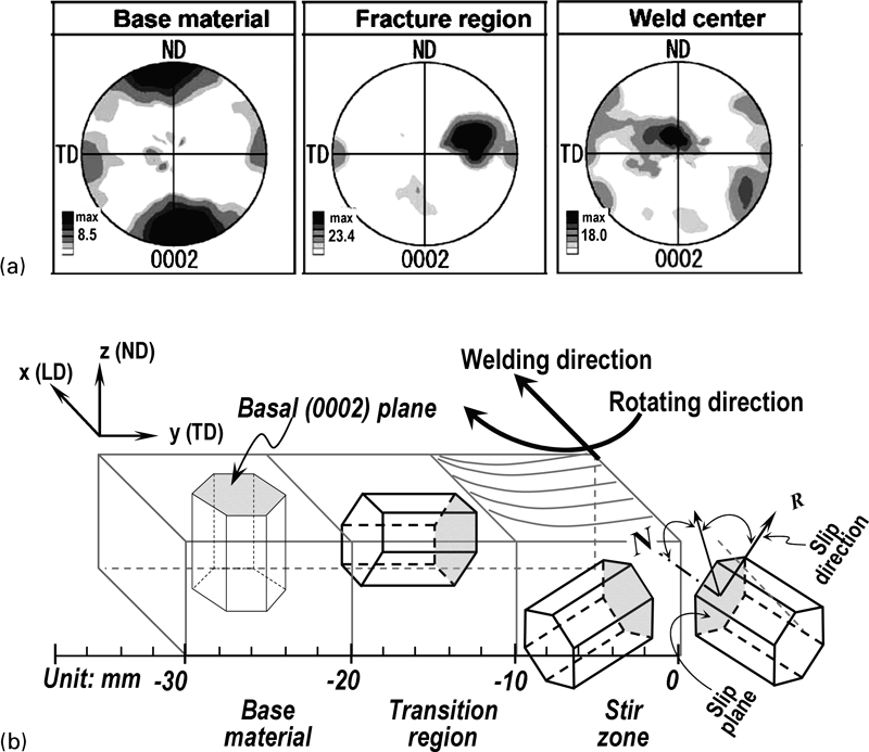
a texture variation of a FSW AZ61 Mg alloy. (0002) pole figures in different regions measured by orientation imaging microscopy.38 b schematic of the preferential slip plane (basal plane) tracing from the base material, transition region, to stir zone of the FSW Mg plate. Changes of the basal planes in the stir zone increased the Schmid factor and, subsequently, enhanced elongation and decreased the tensile strength46
Natural aging effect on residual stresses in FSW of Al alloy
The effect of severe thermomechanical deformation in the FSW Al alloys has been studied extensively to determine changes in the microstructure and mechanical properties.24– 30 Particularly, the hardness and yield strength varied significantly with time due to the dissolution of the strengthening precipitates during FSW and the subsequent reprecipitation behaviour under the natural aging condition in the FSW heat treatable Al alloys.34, 41, 80 Neutron diffraction measurements of residual stresses were performed as a function of time under the natural aging condition in an FSW 6061‐T6 Al alloy.71 It shows how the microstructure changes and the softening/recovery of the strength are related to variations in the macroscopic residual stresses (type I).
Figure 13a shows the macroscopic residual stresses at three different aging times. The results show the decrease in the longitudinal residual stress profile at 10 000 h within the stir zone compared with the profile measured at 2 h after FSW. It is more evident when the observed residual stress changes as a function of aging time (Fig. 13b). In the stir zone, it shows noticeable decreases (∼25 MPa) from about 10 to 400 h after FSW; no significant decreases were observed in the base metal. A similar influence on residual stresses overtime under natural aging conditions has been reported by Linton and Ripley68 using neutron diffraction. They observed a decrease in ∼100 MPa in the longitudinal residual stress within the stir zone in a fully aged 6 mm thick FSW AA7075‐T651 rolled plate.
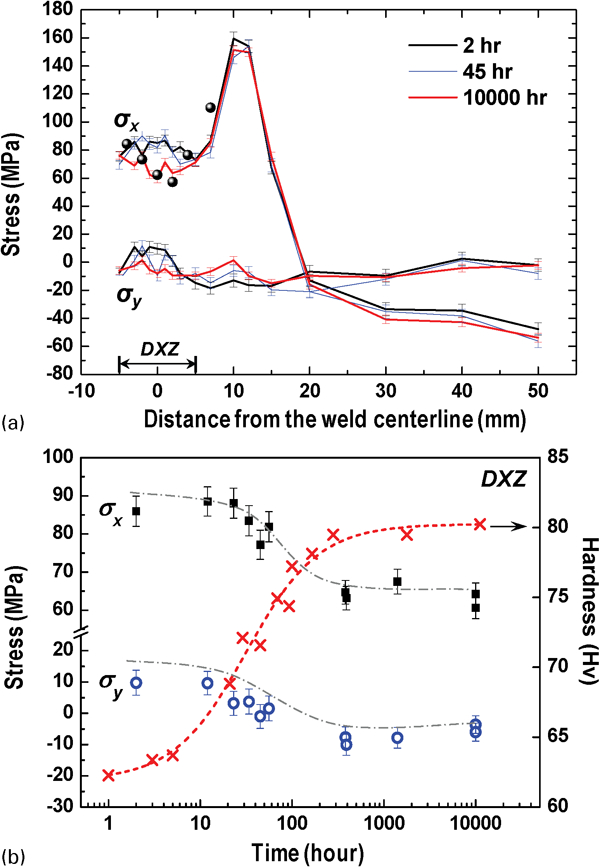
Residual stress variations as a function of natural aging time in a FSW Al 6061‐T6 alloy: a profiles were obtained at about 2, 45 and 10 000 h after FSW. Black dots indicate residual stresses obtained using do, and b profiles measured at the dynamic recrystallised zone (DXZ). Simulated volume fraction fr of precipitates (dotted line profile) is superimposed on the measured hardness (crosses)71
Since such decreases were found mainly in the stir zone, they can be related to the microstructural characteristics of the stir zone under natural aging conditions. Several transmission electron microscope studies show a number of reprecipitates in the stir zone (known as the DXZ) after the natural or artificial aging subsequent to the dissolution of the initial precipitates during FSW.30, 32, 34, 49 Because the strengthening precipitates increase hardness, the hardness changes of the stir zone have been measured as a function of natural aging time, as shown in Fig. 13b. Moreover, the Johnson–Mehl–Avrami relationship81 was used to determine the theoretical kinetics of the relative volume fraction (fr, starts from 0 and ends at 1) for the reprecipitates profiled in Fig. 13b. Interestingly, the residual stresses decreased concurrently with the significant increases in the hardness (∼20 HV recovery). Meanwhile, it was observed that the residual stresses and hardness of the base material remain in the initial state. Therefore, it is believed that the residual stress variations are closely related to the microstructural modification (evolution of reprecipitates) in the DXZ of FSW under natural aging conditions.
In situ observation of stress fields during FSW
Most neutron diffraction work has been limited to the so called ‘static’ behaviour of materials (which does not change with time), primarily because of the inadequate neutron fluxes from existing facilities.9, 10 Recently, an in situ time resolved neutron diffraction method82, 83 was developed and applied for the determinations of the temperature and thermal stress inside the stir zone during FSW of Al 6061‐T6 plate.84 Apparently, measured strains by means of d‐spacing changes as a function of distance from the tool centre during FSW (Fig. 14a), were decomposed into the thermal and elastic strains, and then subsequently were converted to the transient temperature and stress in the bulk of materials.83 The temperature and thermal stress distribution along the weld centreline are shown in Fig. 14b. The temperature monotonically decreases as the distance from the tool centre increases. Because of the relatively low rotational speed (156 rev min−1), the maximum temperature (362°C) attained underneath the tool shoulder was at the low end of the temperature range reported in the literature.24, 25, 41
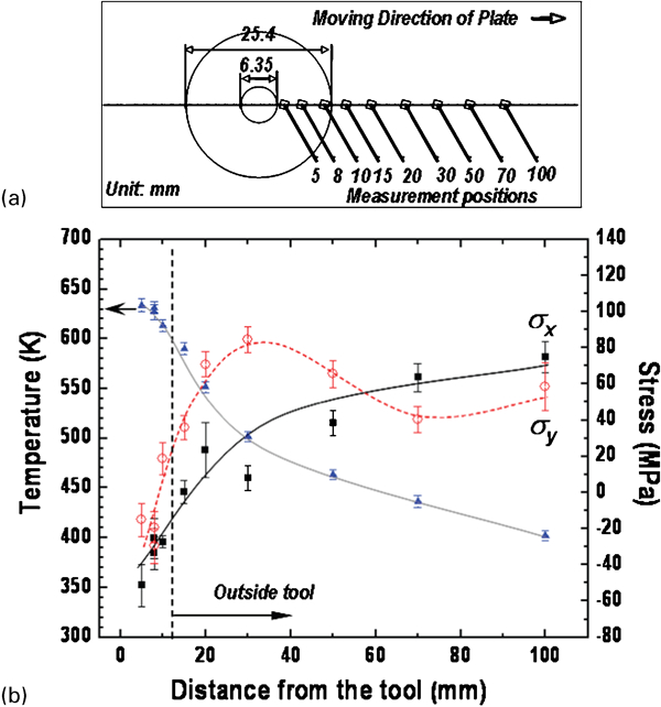
a measurement positions of the in situ FSW experiments. The tool shoulder diameter is 25·4 mm and pin diameter is 6·35 mm. The measurement position was predetermined at 5, 8, 10, 15, 20, 30, 50, 70 and 100 mm behind the welding tool head. b temperature and thermal stress distributions are given along the weld centreline behind the tool as a function of distance from the tool centre. σx: longitudinal (LD); σy: transverse (TD) stress84
As shown in Fig. 14b, both the longitudinal σx and transverse σy stresses were largely in compression under the tool shoulder and were due to the thermal expansion and the forging pressure from the tool shoulder. The longitudinal stress was more compressive than the transverse stress, which can be attributed to the elongated temperature field caused by the moving heat source of friction stir tool along the LD of the plate. Outside the tool, the thermal stresses become tensile to balance the thermal contraction of the weld region. The magnitudes of the tensile stresses (75 MPa for longitudinal stress and 60 MPa for transverse stress) are quite close to that of the residual stresses, which have typically been measured in other studies when the specimen completely cooled down.53, 63
Summary
Neutron diffraction measurement has become one of the new emerging characterisation tools to determine the residual stresses in the welded structures. In this paper, the principle and critical issues in neutron diffraction were summarised in order to calculate the residual stresses in joining materials. Several key examples of neutron diffraction measurements of the residual stresses were highlighted in FSW of Al alloys, Mg alloys and steels. Since the complex thermomechanical FSW process causes significant changes in the microstructure, the authors discussed the influence of the inherent microstructural changes on the mechanical properties (yield strength, hardness) and subsequent residual stress variations. In the end, an in situ neutron diffraction technique for the determination of the temperature and stress fields during FSW was described and the results were discussed.
Footnotes
Acknowledgements
Z. L. Feng and S. A. David were sponsored by the Assistant Secretary for Energy Efficiency and Renewable Energy, Vehicle Technologies Program, as part of the High Temperature Materials Laboratory User Program, Oak Ridge National Laboratory, managed by UT‐Battle, LLC, for the US Department of Energy under contract no. DE‐AC05‐00OR22725. X.‐L.Wang was sponsored by the US Department of Energy, Office of Basic Energy Sciences, Scientific User Facilities Division under Contract no. DE‐AC05‐00OR22725 with UT‐Battelle, LLC. Wanchuck Woo was sponsored by the Nuclear Research and Development Program of the Korea Science and Engineering Foundation funded by the Korean government. The authors would like to thank P. J. Withers, T. Holden, H. Choo, D. W. Brown, B. Clausen, M. B. Prime, C. R. Hubbard and M. I. Ripley for their useful discussions.