
Abstract
The influence of friction stir welding (FSW) on changes in microstructures has been studied extensively. In particular, the microstructural softening, which is manifested as a significant reduction in the hardness, tensile strength and residual stress, is one of the most significant issues. Here, we provide a brief review of the dominant softening mechanisms in FSW aluminium and magnesium alloys available in the literature. In particular, a direct comparison between a heat treatable Al 6061-T6 alloy and an AZ31B Mg alloy is presented to highlight key differences in the underlying mechanisms responsible for the apparently similar softening behaviour. The present study shows that the softening occurs in the wide region of the FSW Al 6061-T6 alloy due to the dissolution of the strengthening precipitates, while it happens mostly within the stir zone due to the localised texture variations in the FSW Mg AZ31B alloy. These softening behaviours are clearly represented in the residual stress profiles.
Review of softening mechanisms in various friction stir welding (FSW) Al and Mg alloys
Friction stir welding has become a well known thermomechanical process to develop a strong metallurgical bonding.1– 4 It relies on the frictional heating and severe plastic deformation, which are produced by a cylindrical rotating tool consisting of the concentric threaded tool pin and shoulder.5– 7 A number of studies have reported significant modifications in microstructure, crystallographic texture, and the mechanical properties including hardness, yield strength and residual stresses, as summarised in Table 1.8– 63 In particular, the localised reduction in the hardness, strength and residual stresses has a strong impact on the failure process and overall integrity of FSW components.64– 67
Summary of softening mechanisms reported for various friction stir weld joints of Al and Mg alloys
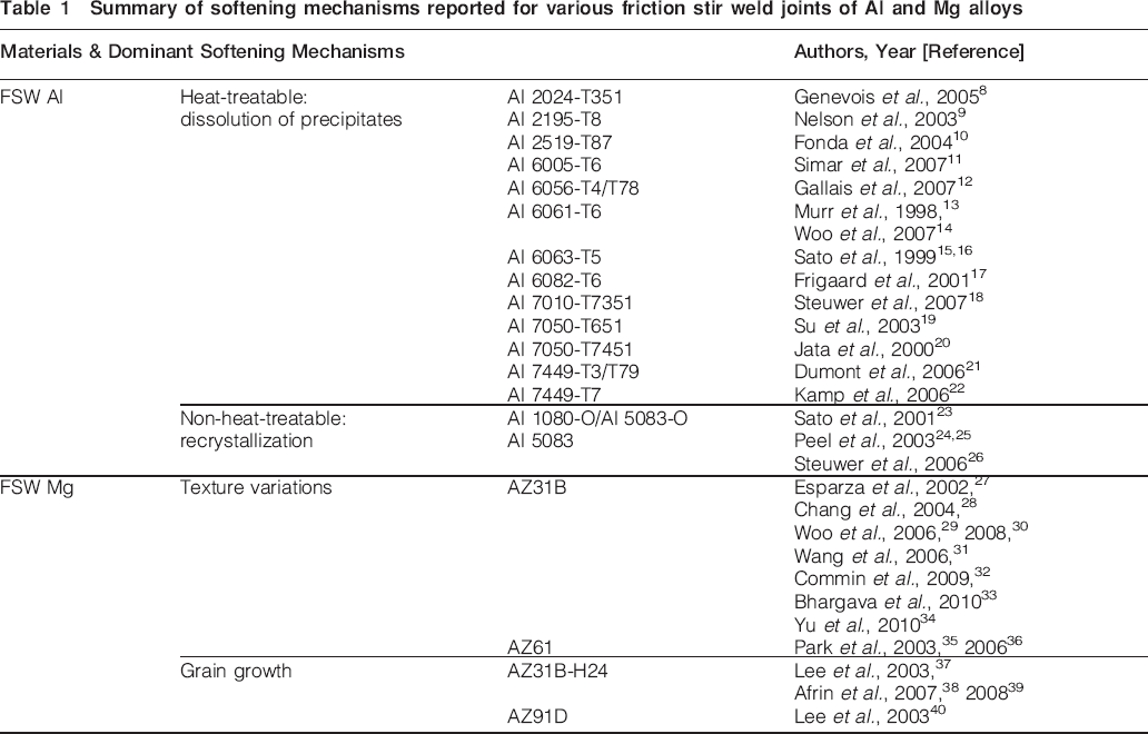
The important microstructure changes in the heat treatable Al alloys are the dissolution or growth of the strengthening precipitates in the FSW affected regions.8– 22 The heat treatable 6xxx Al alloys, for example, contain magnesium and silicon as major alloying elements to form strengthening precipitates such as the GP-I zones, GP-II zones (or β″), β′, and β-Mg2Si.13– 15 Sato et al. 15 showed the dissolution and growth sequences of precipitates as a function of temperature in the FSW 6063 Al alloys. Frigaard et al. 17 developed a process model to estimate the evolution of reprecipitation and resulting hardness distributions in FSW AA6082-T6 and AA7108-T79 alloys. Nelson et al. 9 reported a correlation between changes in the location of hardness minimum and those in the failure location during post-weld natural aging of FSW 7075 Al alloy. In the cases of FSW non-heat treatable Al alloys,23– 26 several studies showed that the recrystallisation and subsequent grain growth were the main reason for the softening. Peel et al. 25 reported that the softening can be as significant as the heat treatable ones from the observations of the hardness distribution in the dissimilar FSW Al 6082 and cold rolled Al 5083. However, in some annealed non-heat treatable Al alloys, the FSW region exhibited a slight increase in hardness compared to the base material (BM) due to the work hardening and grain refinements.4, 23
Similarly, significant microstructure changes during FSW and its influences on the mechanical properties have been reported for various Mg alloys.27– 51 The microstructure changes can be categorised as the texture variation and grain growth (Table 1). Park et al. 35, 36 observed a strong texture development in FSW AZ61 Mg alloy and suggested that the basal plane is roughly aligned with the surface of the tool pin column in the weld region. Woo et al. 29, 30 provided quantitative texture changes in FSW AZ31B Mg alloy using neutron diffraction, which were, in turn, correlated to the reduced yield strength and increased elongation along the longitudinal direction in the weld. Chang et al. 28 and Wang et al. 31 reported that the smaller grain size in the weld did not significantly increase the hardness and suggested a weak grain size dependence in terms of the Hall–Petch relationship in AZ31B Mg alloy. Lee et al. 37 and Afrin et al. 38, 39 observed decreases in hardness in the weld zone in the case of initially strain hardened AZ31B-H24 Mg alloy due to the grain growth.
Comparison between FSW 6061-T6 Al and AZ31B Mg
In this section, we present a critical comparison of two specific examples, namely FSW 6061-T6 Al and AZ31B Mg alloys, to illustrate the differences in the softening mechanisms (dissolution of the precipitates in the Al alloy and texture variations in the Mg alloy) as well as their influence on the material properties in terms of hardness, tensile strength and residual stresses.
Experimental methods
As received commercial 6061-T6 Al alloy rolled plate was solution heat treated and aged for 6 h at 185°C. The nominal chemical composition was Al–1·0Mg–0·6Si–0·3Cu (wt-%). The AZ31B Mg alloy plate was used in the initially hot rolled and soft annealed condition (O tempering) with the composition of Mg–3·0Al–1·0Zn–0·2Mn. In both cases, the dimension of the FSW specimen was 306×306×6·5 mm (Fig. 1). The travelling and rotating speeds were 4·7 mm s−1, 1250 rev min−1 (Al FSW) and 0·97 mm s−1, 600 rev min−1 (Mg FSW) respectively. An H-13 steel tool was used with the dimensions of 19·05 mm shoulder diameter, 6·35 mm pin diameter, and 6·23 mm (Al FSW) and 5·72 mm (Mg FSW) pin lengths.
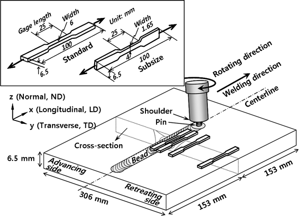
Schematic of FSW process: tensile test specimens were cut along longitudinal direction from both BM and various locations in FSW plates; 19 subsize tensile specimens were prepared with 1·65 mm spatial resolution along transverse direction of weld
Microstructural characterisation was performed at the cross-section of the FSW plates (Fig. 1) for the optical microscopy. Vickers microhardness (HV) was measured in the midthickness across the weld centreline on the polished cross-section using 100 gf (Al FSW) and 50 gf (Mg FSW) applied load. Tensile specimens were machined from the weld (0, 5 and 10 mm from centreline) and BM using electrical discharge machining with the gauge length parallel to the longitudinal (rolling) direction (Fig. 1). The tensile specimens were 6 mm wide, 6·5 mm thick (along the transverse direction of the weld) and 25 mm long in the gauge section (standard tensile specimens), based on ASTM E 8M-04. The test was performed at a constant crosshead velocity with an initial strain rate of 6·7×10−4 s−1 at room temperature. In addition, a total of 19 ‘subsize’ tensile samples were prepared in FSW Mg AZ31B with the gauge length along the longitudinal direction to catch the changes in the tensile behaviour with a better spatial resolution across the weld centreline; these were 4 mm wide, 1·65 mm thick (along the transverse direction of the weld) and 25 mm gauge long as shown in the inset in Fig. 1.
Spatially resolved neutron strain scanning was performed using the spectrometer for materials research at temperature and stress (SMARTS) at Los Alamos Neutron Science Center (LANSCE).68 The spallation neutron source can provide the distinct peaks in a wide range of d-spacings separating the response of each (hkl) orientation among grains with their plane normal parallel to the diffraction vector
A complementary residual stress measurement was performed using a contour method.57, 71 The FSW plate was cut using electrical discharge machining in half on the same plane where the neutron diffraction measurements were taken. The displacements of the cut surface (surface contour) were mapped using a confocal laser probe scanning with a 7 μm diameter spot. The displacements due to the relaxation of the residual stress from the cutting are compared to the flat original surface contour. Analytical computation based on the elastic finite element model provides the stress component normal to the surface of the cut, i.e. σx, for a comparison to the neutron diffraction result.
Microstructure, mechanical properties and residual stresses
The cross-sectional macrostructure of FSW Al 6061-T6 typically shows characteristic regions: the stir zone (SZ), the heat affected zone (HAZ), the thermomechanically affected zone (TMAZ) and BM.14 The SZ has the recrystallised grain structure caused by the severe plastic deformation from the stirring tool pin.10.19 The average grain size was ∼5 μm in the SZ, 110 μm in the HAZ and 120 μm in the BM.66 The FSW AZ31B Mg alloy has similar characteristic regions.30 The average grain size of the SZ (17 μm) is significantly smaller than that of the BM (∼50 μm) and of the HAZ (87 μm).
Figure 2a shows the hardness profile measured in the full natural aging condition in FSW Al 6061-T6.67 The hardness profile shows significant decreases (the minimum of ∼60 HV) near the FSW affected zone compared to 100–110 HV at the BM. The range of the softened region is about ±30 mm from the centreline, which is much wider than the bead width (±10 mm) or the diameter of the tool shoulder pressing the surface of the plate.56 Figure 2b shows the microhardness profile without any noticeable softening. Even though there is a measurable grain refinement in the SZ, no significant increase was observed in the hardness either. It is consistent with other studies in that there is a relatively weak influence of grain refinement on hardness changes in FSW AZ31B Mg alloy.28, 31
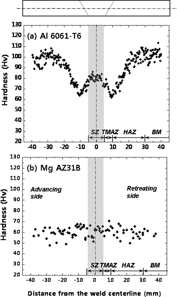
Microhardness measured on cross-section across weld centreline at middle of plate thickness
The tensile tests have been performed along the LD for the FSW Al alloy.66 Table 2 summarised the yield strength σy, the ultimate tensile strength σUTS, the hardening capacity Hc and the strain hardening exponent n. Note that the staining hardening parameters were quantified by using the following equations: Hc = (σUTS−σy)/σy and σ = Kϵn, where σ is the true stress, K is the strength coefficient and ϵ is the true strain. The yield strength of the SZ specimen is significantly lower than that of the BM, even though the grain size is smaller in the SZ. The strain hardening and the total elongation of the SZ specimen are much greater than those of the BM specimen.11, 12 Therefore, for the case of FSW Al alloy, both the hardness profile and tensile stress–strain results clearly show the softening behaviour. Similarly, Table 2 shows a significant reduction in the yield strength (55 MPa) and increases in the strain hardening capacity (4·10) and elongation (35%) in the SZ compared to the properties of BM (110 MPa, 1·75 and 27% respectively) for the FSW Mg alloy. It is interesting to note that for the case of FSW Mg, only the tensile testing (along LD) shows the softening behaviour, while the hardness profile did not indicate such trend. This indicates that the grain refinement within SZ of the FSW Mg does not influence the hardness very much.
Yield strength (σy), ultimate tensile strength (σUTS), hardening capacity (Hc), and strain hardening exponent (n) of the base materials, FSW Al 6061-T6, and FSW Mg AZ31B obtained by standard tensile samples tested along the longitudinal direction
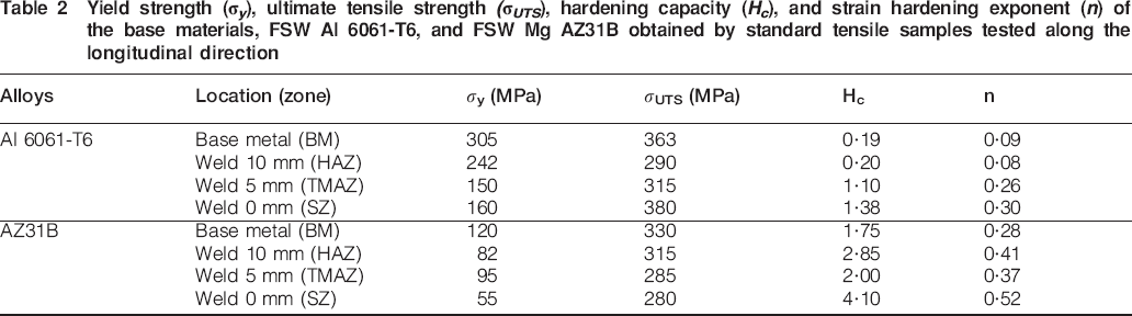
Softening region of the FSW Al 6061-T6 alloy is likely to be much wider than that of the FSW Mg AZ31B. For example, yield strength of the TMAZ (150 MPa, 5 mm from the weld centreline) is similar to that of the SZ (160 MPa) in FSW Al, while σy in the TMAZ (95 MPa) is much higher than that of the SZ (55 MPa) in FSW Mg (Table 2). Figure 3 shows the spatial variation of the longitudinal tensile behaviour in FSW Mg alloy obtained by the tensile tests using 1·65 mm width subsize specimens. The result clearly shows that the significant reduction of the σy (softening) ranges about ±2 mm from the weld centreline.
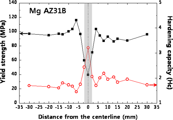
Yield strength σy and hardening capacity Hc variations as function of distance from centreline in FSW Mg AZ31B: results were obtained from subsize specimens with 1·65 mm spatial resolution along transverse direction of weld plate
Figure 4a shows the longitudinal residual stress σx in FSW Al 6061-T6 measured as a function of the distance from the weld centreline using the neutron diffraction technique.58 The characteristic peak-and-valley shape of the σx profile in FSW is consistent with the literature.52– 57 The observed reductions in the yield strength and residual stress near the weld centreline are the manifestation of microstructure softening, which will be discussed more later. Figure 4b shows the σx in the FSW Mg AZ31B measured both by the neutron diffraction and the contour method. The residual stress is compressive (−40 MPa) at 60 mm, increases to maximum tensile stress (135 MPa) at ±3 mm, and sharply decreases to near zero around the weld centreline. The changes are qualitatively similar for σy and σz (not shown here).30 The neutron diffraction result shows a good agreement with that of the contour method (Fig. 4b), which also shows a significant decrease in the residual stress near the weld centreline.
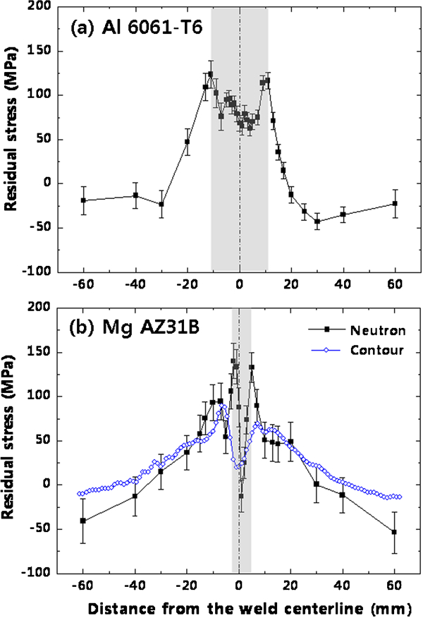
Longitudinal residual stress σx profiles measured using neutron diffraction at cross-section across weld centreline at middle of plate thickness: result of contour method is also included for AZ31B Mg alloy
Softening behaviour and its influence on residual stresses
First, let us discuss the dominant softening mechanism in the FSW 6061-T6 Al alloy. It is known that a high density of the fine needle shaped precipitate β″ is the main source of the strengthening in the heat treatable 6xxx aluminium alloys.11– 17 An in situ temperature measurement result shows that the peak temperature reaches ∼430°C at 8 mm from the centreline during FSW.67 Considering the solvus temperature of the β″ (<353°C),15 the temperatures at SZ and TMAZ are high enough to dissolve the β″ precipitates during the FSW. Such microstructural softening causes the reduction of the hardness and the yield strength in the SZ and TMAZ (±5 mm) of the FSW 6061-T6 Al alloy. Besides, the strain hardening behaviour is significant after yielding (Table 2).12, 66 A recent X-ray line profile analysis study showed that the dislocation density in the recrystallised SZ is ∼2·5 times lower than that of the BM.66, 72 The low dislocation density in the SZ of the FSW Al alloy results in a significantly high strain hardening behaviour after yielding and finally reaches a tensile strength comparable to that of BM.
The residual stresses in FSW are mainly generated by the localised thermal expansion due to the heat input from the tool shoulder under the constraints of cold base materials, followed by a hindered shrinkage during the subsequent cooling.73, 74 The reduction of residual stresses near the weld centreline (Fig. 4a) has been observed in the previous studies as well.3, 4, 52– 63 Since the residual stress field is governed by the as welded yield strength distribution, such reduction of the residual stress is related to the decreased yield strength due to the dissolution (or growth) of the strengthening precipitates via the frictional heating during FSW.14, 24, 56 Notably, recent studies show that the residual stress does not necessarily increase as the softening region is recovered in hardness via reprecipitation after the natural aging.59, 60, 65
For the case of FSW AZ31B Mg, no pronounced variations in the microhardness profile were observed in Fig. 2b. Considering nearly constant chemical composition (not presented here) in all regions across the weld centreline, the dissolution or reprecipitation of a compound is not plausible.30 Meanwhile significant reductions in the yield strength and residual stress of the SZ were clear.
The relationship between texture variations and yield strength reduction, and its influence on the residual stress in the FSW AZ31B are discussed henceforth.29– 36 As received BM has the typical hot rolling texture of Mg alloys, with most of its (0002) basal plane normals parallel to the ND of the plate.35 It has been reported that the preferential basal slip plane (0002) is crystallographically rearranged by the shear plastic flow in the SZ during the FSW.36 The previous texture studies show that the basal (0002) planes are mainly parallel to the ND at BM, mostly parallel to the TD near the TMAZ (∼10 mm) and not parallel to either ND or TD in the stir zone.29, 30, 35 More recent work by Yu et al. 34 shows that the most of the basal poles are oriented about 40° off ND towards LD in the SZ. The results elucidate that the changes in the preferred orientation of the basal planes in the SZ result in increases in the grain sets with a higher Schmid factor compared to the BM in that more grains are inclined to the longitudinal tensile axis. In summary, the higher Schmid factor in the SZ provides the localised reduction in the yield strength, higher elongation and hardening capacity as summarised in Table 2. As a result, the softening in FSW Mg causes a sharp decrease in the residual stress profile as shown in Fig. 4b.
In other studies, FSW Mg AZ31B specimens were prepared with minimal plastic deformation and isolated thermal effect by using a specially designed tool without the threaded pin.56 The results from the heat dominant case showed almost no changes in the texture, the yield strength or the sharp reduction in residual stresses near the weld centreline.30 Therefore, the texture induced yield strength reduction is believed to be the main cause for the residual stress reduction near the SZ in the case of FSW AZ31B Mg alloy.
Summary and remarks
The softening behaviour is summarised for the FSW 6061-T6 Al alloy and AZ31B Mg alloy. The dissolution of the strengthening precipitates due to the frictional heating during FSW is the primary cause of the significant decreases in hardness, yield strength and residual stresses in the FSW affected region of the heat treatable Al 6061-T6 alloy. On the other hand, the softening behaviour of the FSW Mg AZ31B alloy is closely related to the localised texture variations due to the severe plastic deformation during the FSW. It results in a significant reduction in the yield strength and the residual stress in the SZ of the FSW Mg AZ31B alloy. The results of the spatial revolved tensile tests show that the softening region of FSW Mg AZ31B (2±1·65 mm) is much narrower than that of the FSW Al 6061-T6 (5±3 mm). Such softening in microstructure and subsequent reduction in the mechanical strength is represented in the residual stress profiles and can significantly influence the fracture location of FSW components under transverse loading conditions.
Footnotes
Acknowledgements
This work is in part supported by the National Science Foundation (NSF) International Materials Institutes Program under contract no. DMR-0231320. W. Woo is supported by the Nuclear Research and Development Program of the Korea Science and Engineering Foundation funded by the Korean government. The authors also thank Z. Feng, S. A. David, X.-L. Wang, D. W. Brown, B. Clausen and M. B. Prime.