
Abstract
Mild steel with/without zinc coating and magnesium alloy AZ31B were lap joined by friction stir welding during the tool plunging through the magnesium into the steel. With increasing welding speed, the fracture strength increases. At the interface of zinc coated steel and magnesium, a liquid eutectic layer was detected for higher but not for lower welding speeds. At the interface between the steel without zinc coating and magnesium, no melting could be detected.
Introduction
Fuel saving by weight reduction, and thereby improving the body properties, is a challenge in all transport applications. Magnesium alloys have low density, high damping capacity, good castability, weldability and high availability of resources and are recyclable.
Steel is the most common metal in the transport industry, and joining of steel and magnesium is required for weight reduction. The solid solubility of Fe in Mg (0·00041 at‐%) and the different melting points (1538°C for Fe and 650°C for Mg) are the reason why fusion welding of steel and magnesium is extremely difficult. Different techniques joined magnesium and steel with or without an interlayer,1– 7 however joining magnesium and steel by friction stir welding (FSW) is poorly investigated today.
Friction stir welding is a solid‐state joining process8 where a rotating cylindrical tool, consisting of shoulder with a larger diameter and a smaller pin, is plunged into the material and moves along the joint line. The thermally softened material flows around the tool in the direction of the rotation and is deposited in the wake of the weld. The process temperature of FSW is below the melting temperature of the materials; therefore, FSW has no solidification problems associated with conventional fusion welding processes.
It is possible to join magnesium and steel by FSW. Chen and Nakata1 studied the effect of tool geometry on microstructure and mechanical properties of friction stir lap welded magnesium alloy and steel. They used zinc coated and brush finished steel sheets for their investigations and detected an intermetallic compound layer Fe2Al13 but no Zn at the interface of magnesium and zinc coated steel. They reported that the zinc coating improved the weldability of magnesium alloy and steel, and led to a liquid Mg–Zn eutectic, which spread along the interface (far away from the weld centre) till it piled into the natural clearance between two sheets.
Liyanage et al. 5 studied the joint formation in dissimilar Al alloy/steel and Mg alloy/steel friction stir spot welds. They reported that joining of Mg and steel showed no evidence of intermetallic formation at the interface. They found islands of melted Mg–Zn eutectic.
During FSW, heat is generated by friction between the tool and the workpiece and by plastic deformation. The measured peak temperatures for FSW of magnesium are 180–376°C,9, 10 and for spot welding 490°C–580°C.11– 14
Local melting in FSW joints was detected with different materials.11 Firouzdor and Kou10 studied the effect of position with respect to the welding tool for Al–Mg friction stir welds. They reported a liquid film at the interface.
In this study, magnesium alloy AZ31B‐O was joined with zinc coated ultralow carbon steel in lap configuration. The influence of the welding speed on the tensile strength and that of the zinc coating on the interface were investigated. Furthermore, the temperature at the interface close to the weld centre was measured.
Experimental
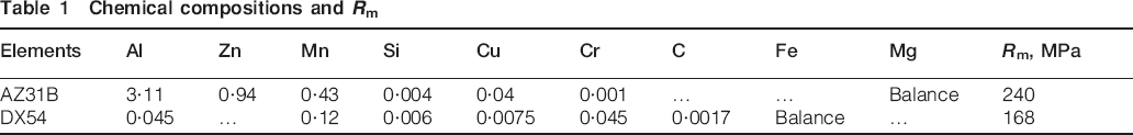
The material used in the present study was a commercial AZ31B magnesium alloy in the annealed condition (O tempering) and an ultra low carbon steel DX54D with a zinc coating thickness of 15 μm. Chemical compositions of the base materials are shown in Table 1. The steel was zinc coated, but for some samples, the zinc was removed.
Chemical compositions and Rm
The dimension of the sheets was 150×150×2 mm. The overlap width was 65 mm, where the magnesium sheet was placed on top. The sheets were clamped with pneumatic pressing bars with 35 mm distance to reduce the displacement during the joining process. The welded joint length is 125 mm.
The tool used in the present study was a tool with an exchangeable pin. The shaft material was a tool steel H13, and the pin consists of 75 wt‐% tungsten and 25 wt‐% rhenium. The shoulder had a diameter of 12·7 mm and was scrolled. The pin length was 2 mm, and the pin had a square shape (3·3×3·3 mm). In the present study, the tool rotation was 1200 rev min−1, and the welding speed was varied between 150 and 500 mm min−1. The plunge depth was 0·15 mm, which means that the pin plunges 0·15 mm into the steel sheet. The tilt angle of the tool was 0°. The FSW machine used for this experiment was MTS ISTIR BR4.
To reduce the influence of the beginning and end of the FSW joint, the samples for the tensile test were cut 30 mm from the starting point of the weld seam.
The temperature was measured at the steel/magnesium interface, 3·5–4 mm away from the weld centreline on the advancing side. At the advancing side, the temperature is expected to be higher due to the plastic deformation.9, 15 K type thermocouples with a sampling rate of 10 Hz were used. The measurements were performed to analyse the temperature history at the interface, which may affect the bonding and strength of the joint.
The peak temperatures in the stir zone of the magnesium alloy were not measured and might be higher than the measured temperatures at the interface.
Results
Temperature measurement
Friction stir welding parameters and the tool design have a big influence on the generation of heat. A constant tool rotation by increasing welding speed decreases the heat input per unit length. The measurements of temperature were performed to investigate the influence of the welding speed on the temperature generation.
Figure 1 shows the measured temperature cycles for the welding speeds of 150 and 500 mm min−1. The measured peak temperature at the interface for the welding speed of 150 mm min−1 was 327°C and that for the welding speed of 500 mm min−1 was 317°C. There was no big difference in the peak temperature, but the time at peak temperature was different.
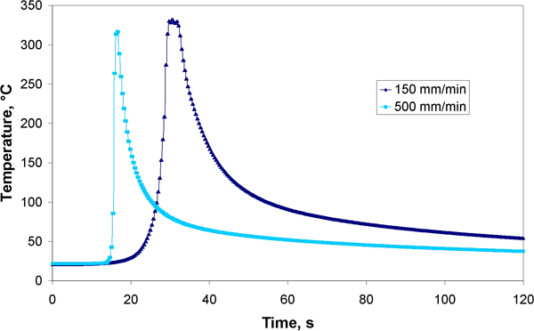
Temperatures measured at interface (1200 rev min−1)
Tensile test
Figure 2 shows the effect of the welding speed on the fracture strength. All other welding parameters are constant (tool rotation, 1200 rev min−1; plunge depth, 0·15 mm into the steel; tilt angle of the tool, 0°) as described in the section on ‘Experimental’. The base material had a thickness of 2 mm, and the shoulder plunged 0·15 mm into the magnesium sheet, which reduced the sheet thickness to 1·85 mm.
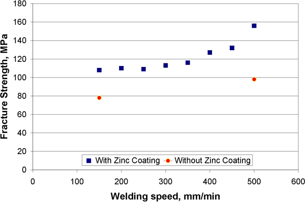
Effect of welding speed on tensile strength
The quadratic points display the fracture strength with zinc coating, whereas the dots stand for the fracture strength of the joint using steel without zinc coating.
The fracture strength increases with increasing welding speed, and the fracture strength of the samples with zinc coating is higher than that without coating. All samples fractured in the stir zone, which means that the fracture strength of the steel/magnesium interface is higher than the measured strength.
Metallography
Welding speed of 150 mm min−1 with zinc
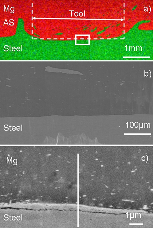
Figure 3a displays an EDX map of the cross‐section at the welding speed of 150 mm min−1, where the magnesium sheet is at the top. The white dashed line displays the position of the tool pin. The advancing side is on the left hand side where iron particles moved. Figure 3b shows the stir zone where the magnesium sheet is at the top. The white line displays the ion beam polished area. It was possible to detect some steel particles in the magnesium alloy, but no defects were identified. Figure 3c shows the interface and a steel particle. The interface was without any intermetallic phase (Fe2Al13). Around the steel particles, some voids are visible. The EDX line (Fig. 4) across the interface shows higher zinc content at the interface.
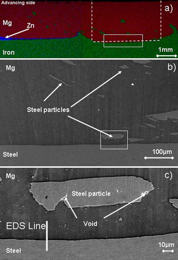
a EDX map of cross‐section, b stir zone and c interface with EDX lines position for welding speed of 150 mm min−1
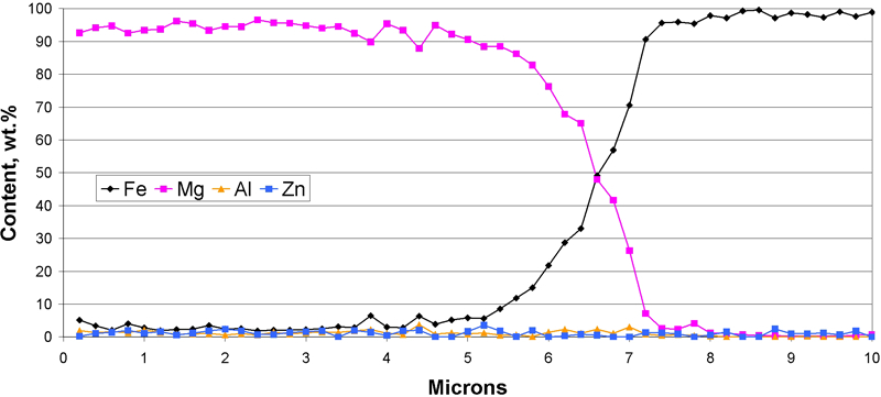
Energy dispersive X‐ray line (Fig. 3c, top down) scan over interface for welding speed of 150 mm min−1
Welding speed of 500 mm min−1 with zinc
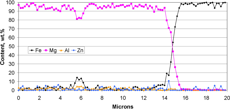
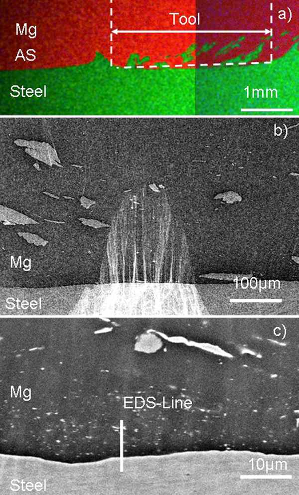
Figure 5a shows an EDX map of the cross‐section where the advancing side is on the left hand side. The magnesium sheet is at the top, and at the interface between the magnesium and steel sheet is a thin zinc layer. Figure 5b shows the stir zone where the magnesium sheet is at the top and big steel particles were in the stir zone. At the interface is a layer with the thickness of ∼50 μm. Figure 5c and d shows the interface at two different positions in detail. The zinc layer at the interface has a lamellar structure. Different EDX lines across the interface (Figs. 6 and 7) shows that zinc content at the interface is always the same.
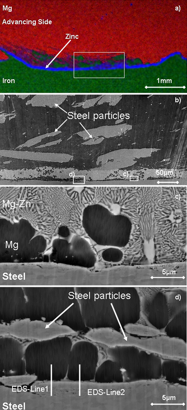
a EDX map of cross‐section, b stir zone, c interface with Zn layer and d interface with EDX lines position for welding speed of 500 mm min−1
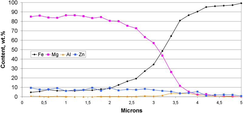
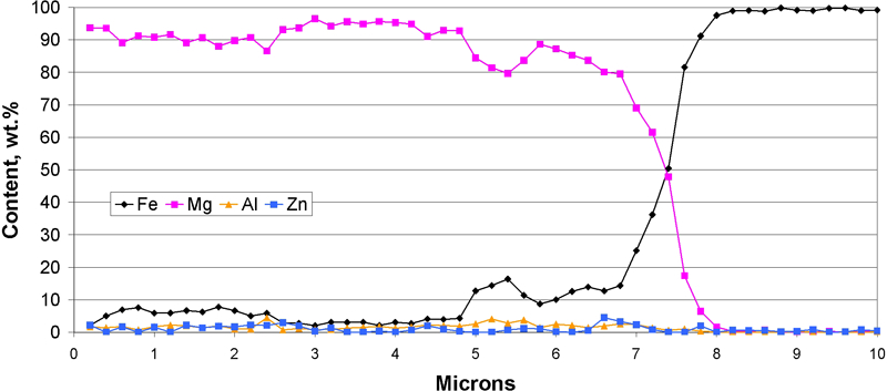
Energy dispersive X‐ray line 1 (Fig. 5d, top down) over interface for welding speed of 500 mm min−1
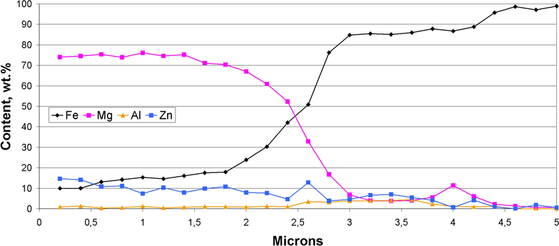
Energy dispersive X‐ray line 2 (Fig. 5d, top down) over interface for welding speed of 500 mm min−1
Welding speed of 150 mm min−1 without zinc
Figure 8 shows the interface of steel and magnesium at the welding speed of 150 mm min−1. The advancing side is at the right hand side, and in the magnesium sheet are steel particles. No defects were detected. The EDX line (Fig. 9) across the interface shows no zinc or aluminium peak at the interface. At the interface, particles with a size smaller than 1 μm were detected. The EDX line shows a higher content of iron in the magnesium sheet, which could be a sign for small steel particles in the magnesium sheet.
a EDX map stir zone, b stir zone and c interface with EDX lines position for welding speed of 150 mm min−1 without zinc
Energy dispersive X‐ray line 1 (Fig. 8c, top down) over interface for welding speed of 150 mm min−1 without zinc
Welding speed of 500 mm min−1 without zinc
Figure 10 shows the interface of steel and magnesium at the stir zone. The magnesium sheet is on the top, and the advancing side is on the left hand side. No defects were detected at the interface, and the EDX line (Fig. 11) shows the same result as for the welding speed of 150 mm min−1 without zinc coating. Small steel particles are in the magnesium sheet, but no higher zinc or aluminium content was detected.
Interface without zinc coating and at welding speed of 500 mm min−1
Energy dispersive X‐ray line 1 (Fig. 10c, top down) over interface for welding speed of 500 mm min−1 without zinc
Discussion
The measured peak temperature at the interface of ∼332°C at a welding speed of 150 mm min−1 was only ∼10°C higher than that at a welding speed of 500 mm min−1, which means that the influence of the welding speed on the peak temperature is very low in the investigated range (see Fig. 1). The duration of peak temperature for the welding speed of 150 mm min−1 was a few seconds longer. Figure 2 shows that the tensile strength increases with increasing welding speed. The strength of the samples with zinc coating was systematically higher than that of the samples without coating. All samples fractured in the stir zone but not in the interface of steel and magnesium alloy. Owing to this behaviour, the fracture strength of the interface can be estimated to be higher than the measured strength.
The magnesium zinc phase diagram (Fig. 12) shows melting temperature of zinc at 419°C and magnesium at 650°C and a eutectic point at 53 wt‐%Zn with a melting temperature of 341°C.
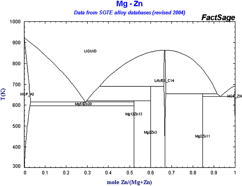
Phase diagram of magnesium zinc
At the welding speed of 500 mm min−1, a layer with the thickness of 50 μm and a eutectic structure was detected at the interface of the joint. This eutectic layer is an indicator for local melting and, therefore, a liquid phase during the joining process. The reason for melting is diffusion from zinc into the magnesium, which decreases the melting temperature according to the phase diagram. Some magnesium grains were detected in this layer and between the eutectic magnesium–zinc layer and the steel sheet. This magnesium grains are segregations from the liquid layer during the solidification.
At the welding speed of 150 mm min−1, no eutectic layer could be detected, but the zinc content was higher at the interface. The eutectic magnesium–zinc layer may flow out of the joining area. The difference between these two samples was only the welding speed. A lower welding speed means more stirring per length unit but no significant higher peak temperature. The forge force at a lower welding speed was ∼5 kN and at a higher welding speed was 8·2 kN. This shows that a higher forge force is not the reason why the liquid layer flows out of the interface. Only the forced material flow because of the stirring could be the reason.
No eutectic layer between steel and magnesium was detected for the samples without the zinc coating, which explains that there was no melting during the joining process in this case. No difference in interfaces could be detected.
The fracture strength was higher with a liquid layer during welding in the interface. It is assumed that the zinc coating acts like a flux as it is known from steel to aluminium joining. Furthermore, the liquid eutectic alloy fills up pores during the process, reducing local notch effects of pores or small cracks acting as crack initiation sites.
Different researchers reported that local melting during FSW was observed.10, 16, 17 All used alloys where the phase diagrams of the material showed a eutectic point (for example, magnesium and aluminium) or they carried out dissimilar welding where the different materials joined showed a eutectic point in the phase diagram.
In the present study, the eutectic system magnesium–zinc is the reason for local melting. The magnesium alloy AZ31 consists of zinc and aluminium, which are both forming eutectic systems with magnesium. Nevertheless, zinc content of the Mg alloy itself is too low, but the zinc content at the interface due to the zinc coated steel is sufficient for the establishment of a significant amount of magnesium–zinc eutectic, leading to a local liquid phase during FSW improving the strength of steel to AZ31 weld.
Conclusions
All samples fractured in the stir zone, indicating that the fracture strength of the interface is higher than the measured strength. With increasing welding speed, the fracture strength increased.
The zinc coating of the steel sheet acts like a flux leading to a more reactive steel surface and additionally forms liquid eutectic layer during the process. Both effects cause a significantly higher strength of the interface compared to uncoated steels sheets.