
Abstract
In materials such as Ni based alloys, the microstructures are formed by monophase solidification without solid state transformation. It is difficult to obtain the welding residual stress by X-ray diffraction because of the preferred orientation of the unidirectional solidification and the grain growth in the heat affected zone. To exclude their effect, a method that records the diffraction peaks in a two-dimensional detector combined with multiaxial rocking is proposed. It is clarified that the equilibrium of shrinkage and the recovery of strain during the thermal cycle determines the site of the maximum tensile stress. In addition, dynamic recrystallisation, which occurs during welding, contributes to the decreased residual stress at the fusion line. If the spatial resolution of the proposed and the conventional measurement methods can be correlated, the results of each method agree well. Therefore, the proposed method is an effective tool for measuring the residual stress in welded joints of Ni based alloy.
Keywords
Introduction
In recent years, the demands for nuclear power generation that can reduce the emissions of CO2 have been growing. However, primary water stress corrosion cracking,1 which occurs in the welds of Ni based alloy, such as Inconel alloy 600, causes degradation in pressurised water reactors. The environment, the material and especially the tensile residual stress due to welding contribute to the cracking. Therefore, it is important to obtain the detailed residual stress distribution in the welds of Ni based alloy for the evaluation of primary water stress corrosion cracking initiation. There are several ways to measure the residual stress distribution in the welded zone. Hole drilling2 and stress relief methods are the most common mechanical methods, but there are also non-destructive methods such as laboratory X-ray, synchrotron radiation3– 7 and neutron.8– 14
During welding thermal cycle, the microstructures in the welded zone change from the original microstructures. The systems of monophase solidification without solid state transformation in materials such as fully austenitic stainless steel and Ni based alloy make it difficult to conduct non-destructive measurements because of their preferred orientation due to the unidirectional solidification and the grain growth in the heat affected zone. So, strain scanning methods3– 13 (e.g. transmission method) with hard synchrotron X-rays have recently been employed. However, improved accuracy of the reflection method with laboratory X-rays is desired, since synchrotron radiation and neutron are usually not available. Meanwhile, due to the influence of the preferred orientation and grain growth, Laue spots are not always detected as corresponding to the equator with a zero- or one-dimensional detector. Therefore, it is necessary to establish a measurement method that can evaluate the accurate scattering angle (i.e. elastic strain) of the welded zone. To exclude the effect of preferred orientation and grain growth, a method is proposed to record the diffraction peaks in a two-dimensional detector in combination with multiaxial rocking before conducting the stress analysis. In this paper, a method to improve the accuracy of X-ray stress measurements in welds of Ni based alloy is discussed.
Experimental
Materials
The material tested is type 600 Ni based alloy with a chemical composition of 0·009C–0·16Si–0·14Mn–73·98Ni–16·59Cr–6·45Fe–0·02Cu–2·34Nb–0·05Co (mass-%). The machined specimen was a thin plate with size of 150×100×8 mm. Electrical polishing with 5% perchlorate methanol was performed to eliminate the initial residual stress induced by the machining process. After reaching a polished depth of ∼300 μm, the initial residual stress was reduced to almost zero. The specimen was then welded under the following bead on plate gas tungsten arc welding conditions: welding current 128 A, arc voltage 10·6 V, travelling speed 10 m min−1. Argon was used as the shielding gas at a flowrate of 15 L min−1.
It is well known that the dendrites in a face centred cubic preferentially grow along the 〈100〉 direction,15, 16 because {111} is the slowest growing plane. The 〈100〉 direction is most closely aligned with the heat flow direction (i.e. normal to the solidification front). The dendrites whose trunks are most closely aligned in this direction grow with the slowest velocity and thus require the least undercooling. Thus, the shape of the molten pool is an important factor in the growth of dendrites. The above welding conditions for this specimen size were purposely adopted to make the X-ray residual stress measurement in the welded zone difficult.
X-ray residual stress measurement by using two-dimensional detector
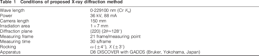
The change of the d spacing was measured by the two-dimensional detector as the elastic strain, since a large 2θ (diffraction angle) and γ (angle on Debye–Scherrer ring) can be obtained simultaneously. The conditions of the measurement method are presented in Table 1, and the schematic geometry is shown in Fig. 1. As the goniometer, an Eulerian cradle that can perform ω and X rocking, ψ tilt and φ rotation at the same time was used to consider the preferred orientation and coarse grain. The wave distribution was limited to the incident angle ω by a monochromator. Then, rocking of ω by ±4° was performed at the junction of the reciprocal lattice points and the Ewald sphere, because the Laue condition satisfies for the specific energy, shown by either Kα1 or Kα2 due to the preferred orientation and grain growth. In parallel, in the welding direction X, rocking of ±3 mm was also carried out by taking advantage of the characteristic feature, which is the constant distribution of the welding residual stress in this direction. Moreover, the γ direction of the two-dimensional detector corresponds to the group of Laue spots around the incident beam (i.e. multiaxial rocking). To obtain the behaviour in three-dimensional space, the measurement was performed with ψ tilt and φ rotation. And then, in order to keep the gauge volumes constant during the measurement, the irradiation area of the specimen surface was limited to 7 mm in the welding direction by 1 mm in the transverse direction by using a masking.
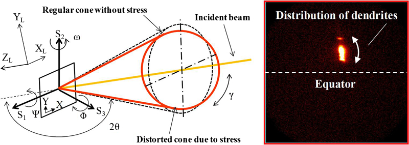
Geometry of diffraction system for stress measurement
Conditions of proposed X-ray diffraction method
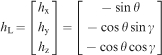
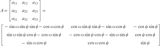
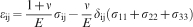
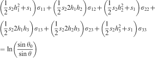
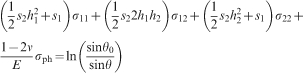
The measured strain was converted into residual stress by using the stress model proposed by He.17 The unit vector of the diffraction vector hL is given in the laboratory system (XL,YL,ZL) as
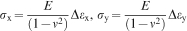
Selection of elastic constants for stress analysis
Since the lattice strain measured by X-ray diffraction differs from the mechanical strain, the stress analysis must consider the dependence of the diffraction plane. That is, the X-ray elastic constants must be estimated. From the elastic compliances for a single crystal, the X-ray elastic constants can be estimated by the Kroner model.18 This model assumes that, in any elastic–anisotropic single crystal placed in a homogeneous matrix, the stress continuity is a boundary condition. In addition, the average of the stress and strain against each grain equals that of the homogeneous matrix. The behaviour of a single crystal is given by
 is the total deformation and
 is deformation by elastic anisotropy. The homogeneous matrix is

Conventional methods
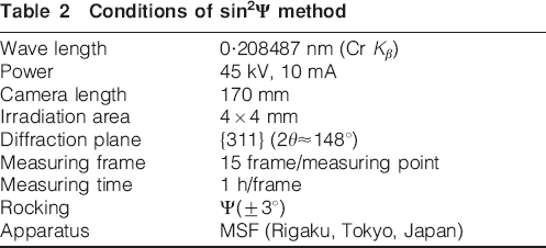
To verify the results of the residual stress measurement by the two-dimensional detector, the results were compared with those of a conventional method. The sin2Ψ 15-point method19 was used as the conventional X-ray diffraction method. The measurement conditions are shown in Table 2. The diffraction peak was detected with a scintillation counter (zero-dimensional detector), and a soller slit was placed in front of the light source and the detector to decrease the background. The scattering angle of peak {311} by Cr Kβ was ∼148°. To average the sin2Ψ plots to exclude the preferred orientation and coarse grain, Ψ rocking of ±3° was performed. In order to keep the gauge volumes constant during the measurement, the irradiation area of the specimen surface was constantly limited to 4 mm in the welding direction by 4 mm in the transverse direction by using a masking. The elastic constant considering the dependence of the diffraction plane was the same as that by the two-dimensional detector.
Conditions of sin2Ψ method
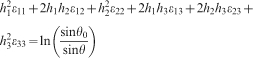
In addition, the stress relief method was performed as the conventional cutting method. Small pieces were cut from the specimen, as shown in Fig. 2, and so the residual stress was physically released. The residual stress was converted into mechanical elastic strain, which is the difference before and after cutting, given as follows
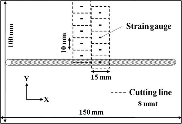
Schematic illustration of stress relief method
Results and discussion
X-ray elastic constants of Ni based alloy
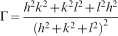
Figure 3 shows the X-ray elastic constants considering the dependence of the diffraction plane estimated by the Kroner model. The horizontal axis denotes the orientation parameter, given by
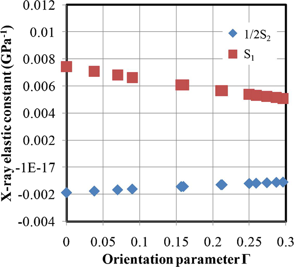
X-ray elastic constants calculated by Kroner model utilising single crystal contents
Welding residual stress distribution
Figure 4 shows the detailed residual stress distributions in the weld of type 600 Ni based alloy evaluated by the two-dimensional detector in combination with multiaxial rocking. For this system of monophase solidification without solid state transformation, a typical welding residual stress distribution could be obtained. The tensile residual stress in the welding direction decreased from the weld centre to the fusion line. The solution strengthening near the fusion line decreased due to the redistribution of solutes during the crystal growth. But, the decreased residual stress is poorly supported by only this event, and so it is further explained below. The tensile residual stress increased from the fusion line to the heat affected zone at the mid-temperature and indicated the maximum value of 270 MPa at a distance of 7 mm from the weld centre. After that, the stress in the welding direction became compressive stress at a distance of 20 mm from the weld centre. It is possible that the recovery of strain is initiated at the high temperature side, that is, in the weld metal and heat affected zone, despite the shrinkage due to the welding. In other words, the equilibrium of shrinkage due to the thermal strain and the recovery of strain during the thermal cycle determines the site for the maximum tensile stress. This corresponds to the micro Vickers hardness distribution by load of 0·49 N as shown in Fig. 5. The hardness was 230 HV in the weld metal, whereas it was as high as 345 HV in the mid-temperature region of the heat affected zone.
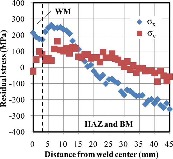
Residual stress distribution due to welding by proposed X-ray diffraction method: gauge volume is 7 mm in welding direction by 1 mm in transverse direction by 9 μm in depth direction; BM, base metal; WM, weld metal; HAZ, heat affected zone
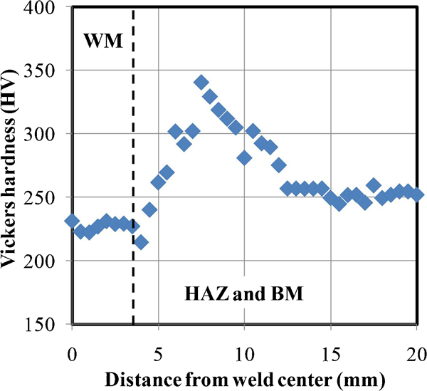
Vickers hardness distribution in measurement region obtained by load of 0·49 N: BM, base metal; WM, weld metal; HAZ, heat affected zone
In contrast, the tensile residual stress perpendicular to the welding direction indicated a maximum value of 141 MPa at a distance of 8 mm from the weld centre and decreased towards the weld centre. The bending moment by angular distortion caused the compression. In summary, the stress decrease near the fusion line was initiated not only in the direction of welding but also in the direction perpendicular to the welding. Thus, it is necessary to investigate the effect of the microstructure evolution on the residual stress during the welding process.
Effect of microstructure on welding residual stress
Electron backscattered diffraction was performed to confirm the metallurgical characteristics that affect the welding residual stress. The observation field on the bead surface was mechanically polished, and then electrical polishing by 5% perchlorate methanol was carried out. The orientation mapping was carried out with a step size of 5 μm because of the wide observation field. Figure 6 shows the inverse pole figure map in the weld of the 600 Ni based alloy. The weld metal has the texture of coarse grain. The maximum aspect ratio of the columnar grain is ∼25∶1 and the size in the width direction is ∼200 μm. The mid-temperature region of the heat affected zone has the highest tensile stress in the welding direction for a grain size of 80 μm, and crystal rotation is due to the plastic strain within the grain. In contrast, the grain size of the heat affected zone near the fusion line is reduced in size and no crystal rotation is observed. It is thought that the precipitation and growth of the stress free crystal was initiated by the dynamic recrystallisation during welding. This factor also contributes to the decrease in residual stress at the fusion line.
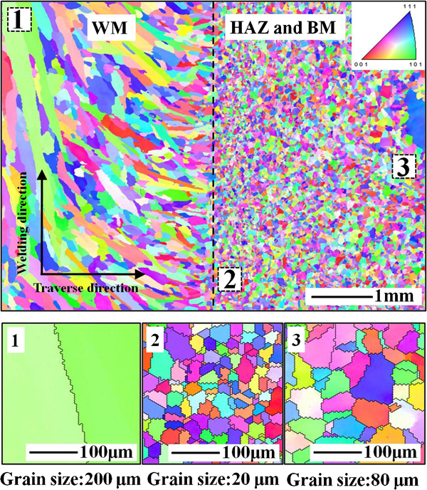
Inverse pole figure map on specimen surface measurement by proposed X-ray diffraction method: BM, base metal; WM, weld metal; HAZ, heat affected zone
Comparison with conventional method
As shown in Fig. 7, the residual stress distribution measured by the two-dimensional detector combined with the multiaxial rocking agrees very well with the distribution measured by conventional methods, if the spatial resolution in the transverse direction is averaged as possible. Even though the stress relief method evaluates the average value of the small pieces cut from the specimen, the reason for its agreement with the X-ray diffraction method is shown in the following. The thermal gradient in the thickness direction becomes smaller by the influence of the thermal reflection, because of the use of the thin plate with the heat input. The residual stress distribution in the thickness direction then becomes approximately constant. That is, two of the X-ray diffraction methods and the stress relief method measured the same stress, and the results of the proposed method, shown in Fig. 4, are verified to be accurate. Therefore, the two-dimensional detector in combination with multiaxial rocking is effective for measuring the welding residual stress in microstructures formed by monophase solidification without solid state transformation, which are found in materials such as fully austenitic stainless steel and Ni based alloy.
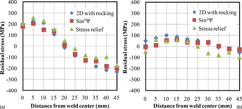
Comparison of residual stress distribution in type 600 Ni based alloy measured by proposed X-ray diffraction method (data averaged 10 mm in transverse direction), sin2Ψ method (as measured) and stress relief method (as measured)
Conclusions
Using the two-dimensional detector in combination with multiaxial rocking, the welding residual stress in microstructures formed by monophase solidification without solid state transformation can be accurately measured.
The weld of Ni based alloy has a local maximum stress at the mid-temperature region of the heat affected zone. It is thought that the equilibrium of the shrinkage due to the welding and the recovery of the strain determines the site of the maximum residual stress.
It is clarified that the precipitation and growth of the stress free crystal is initiated by the dynamic recrystallisation during the welding. This factor contributes to the decrease in residual stress at the fusion line.
The residual stress distribution measured by the two-dimensional detector in combination with multiaxial rocking agrees very well with the results of conventional methods such as the stress relief method and sin2Ψ method.