
Abstract
Dissimilar material components such as clad welds are important to achieve both performance, and economic and ecological efficiency. The evaluation of the residual stress distribution in such components is needed to assess and assure the integrity of structures components. In this study, the residual stress distribution in clad welds of Ni base alloy over low alloy steel was investigated. A clad welded mock-up was fabricated, and the residual stress distribution was evaluated by X-ray stress measurement method and finite element simulation. The residual stress was measured with high accuracy even in coarsened Ni base alloy clad weld metal by X-ray stress measurement method utilising a two-dimensional detector and multiaxial rocking technique. The residual stress distribution was well reproduced by the finite element simulation considering the redistribution due to cutting off of the specimen from the fabricated mock-up.
Keywords
Introduction
Renewable energy sources are being focused recently, and numerous discussions are continuing about the utilisation of nuclear power. However, it is difficult to meet the increasing energy demand only by existing renewable energy sources at present. Therefore, the nuclear power generation is expected to play an important role in electric power supply at least until sufficient generation to meet demand is achieved by alternative renewable energy sources. Since nuclear power plants continue to operate for the immediate future, appropriate measures to maintain and even enhance the safety of nuclear power plants should be taken more than ever.
Stress corrosion cracking (SCC) is one of the critical issues affecting the operation of nuclear power plants.1– 3 Therefore, the evaluation of the occurrence of cracks and the extension of detected cracks are important. Generally, the governing factors of SCC are stress, material and water environment. In this paper, weld residual stress is the focus. The evaluation of weld residual stress is important as it affects the initiation and propagation of cracks.4– 6
The evaluation of weld residual stress is usually performed by the following two major approaches: experimental measurement and numerical simulation. In many cases, subscale mock-ups of actual components are fabricated, and the residual stress measurement and the numerical simulation are performed. The result of the numerical simulation is validated by comparison with experimental results, and then the effect of various parameters on weld residual stress is discussed by using the numerical simulation. Therefore, both approaches are essential in the evaluation of weld residual stress. In addition, in order to check if existing plant components fit to the present codes and regulations, experimental measurements would be difficult in many cases and the numerical simulation would play a more important role hereafter.
In this study, the weld residual stress distribution in clad welds of the inner surface of reactor pressure vessels was discussed. Such dissimilar welds are indispensable to achieve both performance, and economic and ecological efficiency in various fields, not only in the nuclear power plant components. A mock-up in which Ni base alloy was weld cladded over low alloy steel was fabricated, and the evaluation of the residual stress distribution by X-ray stress measurement method and numerical simulation was conducted in this paper.
Experimental
A clad weld mock-up modelling clad welds over inner surface of reactor pressure vessels was fabricated. Measurement of temperature profile, macroscopic and microscopic observation, and residual stress measurement was performed as follows in order to determine conditions of numerical simulation and to validate the simulation result.
Fabrication of clad weld specimen and measurement of temperature profile
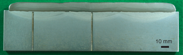
A clad weld mock-up shown in Fig. 1 was fabricated. Ni base alloy weld metal was weld cladded on the surface of the low alloy steel block by submerged arc welding using band electrode. The geometry of the low alloy steel block was 230 mm wide, 410 mm long and 167 mm thick. Materials used were low alloy steel for pressure vessels (specified as SQV2A in JIS G 3120) and Ni alloy strip electrodes for welding (specified as BNi6082 in JIS Z 3334). The chemical composition of materials used is summarised in Table 1.
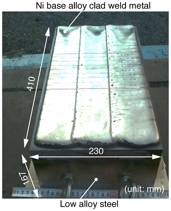
Fabricated clad weld mock-up
Chemical composition of materials used, mass-%
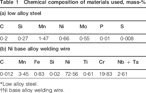
*Low alloy steel.
†Ni base alloy welding wire.
The deposition sequence of weld passes was two layers and six passes as shown in Fig. 2. A cross-section perpendicular to the welding direction is shown in the figure. Welding current, arc voltage and welding speed were set to 1200 A, 28 V and 3 mm s−1 ( = 18 cm min−1) respectively. The low alloy steel was preheated to 100°C by burner before clad welding started, and interpass temperatures were kept between 100 and 150°C for following passes. Temperature profile around the welds was measured by thermocouples inserted through drilled holes as shown in Fig. 3. The holes reached the location beneath the centre of pass 1 in horizontal direction. In addition, the location of the holes in vertical direction was targeted to be 1, 2, 3 and 4 mm from the weld fusion line of pass 1. These thermocouples are referred to as TC1, TC2, TC3 and TC4 respectively. The measured temperature profiles were compared with the results of the numerical simulation performed in the following part of this paper in order to determine and validate the conditions for the numerical simulation. The weld cross-section was observed after welding in order to check the weld pass sequence and the location of inserted thermocouples. Usually, a post-weld heat treatment is conducted after welding in clad welds; however, the study was conducted on the as welded specimen as a basic study.
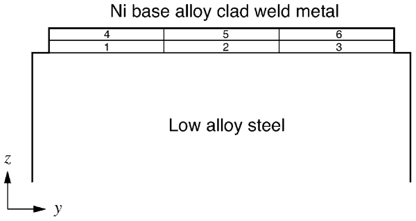
Pass deposition sequence of clad welds
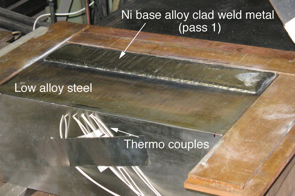
Thermocouples inserted through drilled holes
Residual stress measurement
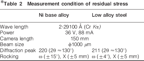
The residual stress distribution in the clad welds was measured by X-ray residual stress measurement method. The specimen for the measurement was cut off from the fabricated clad weld joint as shown in Fig. 4 to include passes 1 and 4. The line for X-ray residual stress measurements is also shown in Fig. 4. As the grain size was expected to be quite large and preferred orientation would be observed especially in the clad weld metal of Ni base alloy of fabricated mock-up, the measurement was performed by the X-ray residual stress measurement system equipped with a two-dimensional detector and multiaxial rocking.7 The measurement condition is summarised in Table 2. The result of the measurement was compared with the results of numerical simulation.
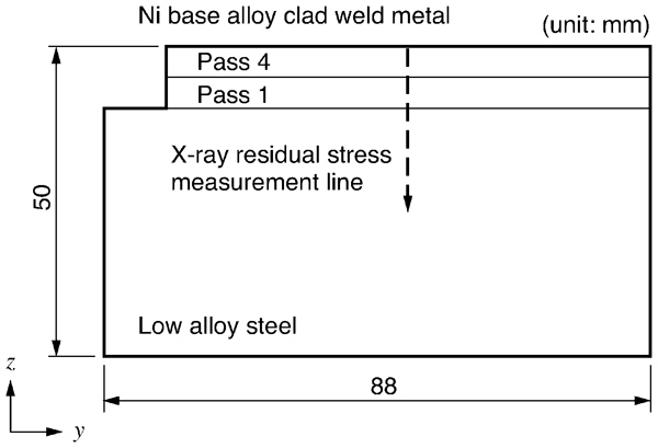
Specimen for residual stress measurement
Measurement condition of residual stress
Simulation model of residual stress distribution in clad welds
The residual stress distribution in the clad welds was calculated by finite element method.8 The finite element analysis software used was SYSWELD.9 The finite element model used in the simulation is shown in Fig. 5. The cross-section of the fabricated clad weld specimen perpendicular to the weld direction was modelled. The numerical simulation was performed under plane strain condition. However, in this simulation model, three-dimensional finite elements were used and the two surfaces in y–z plane were fixed. This is because the effect of redistribution due to cutting off procedure should be taken into consideration in order to compare the calculated residual stress distribution with the measurement results, as the experiment was performed using the specimen cut off from the fabricated clad weld specimen as described in the previous section.
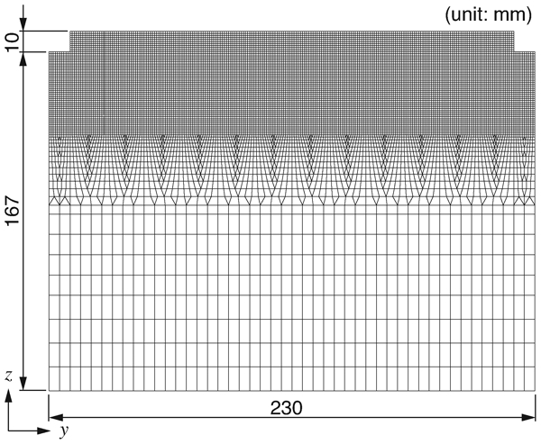
Finite element model of clad weld mock-up
Material properties of Ni base alloy weld metal and low alloy steel used in the numerical simulation are shown in Figure 6 Figs. 6–8. For the low alloy steel, the change in material properties due to phase transformation was taken into consideration. The low alloy steel changes its state from the initial phase to the austenite phase between temperatures Ac1 and Ac3 during heating, and the austenite phase to transformed phase between Ar3 and Ar1 during cooling. The fraction of phase supposed to change linearly in between Ac1 and Ac3 or Ar3 and Ar1 in the numerical simulation. For the yield stress of the low alloy steel, two temperature dependent curves were used for the initial and transformed phases as shown in Fig. 7. The volumetric expansion due to phase transformation was also taken into consideration using phase dependent different thermal expansion coefficients for the low alloy steel. The thermal expansion coefficient for the initial and transformed phases was set to 1·1×10–5°C–1 and for austenite phase to 1·7×10–5°C–1. The thermal expansion coefficient for Ni base alloy was set to 1·7×10–5°C–1.
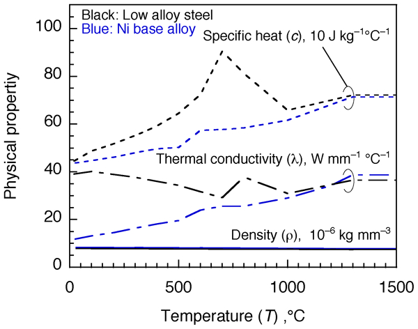
Temperature dependence of physical properties
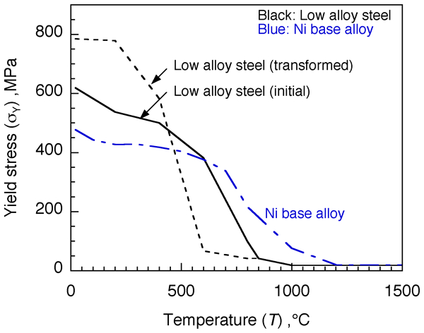
Temperature dependence of yield stress
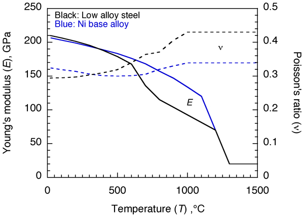
Temperature dependence of elastic properties
The numerical simulation of weld residual stress was performed in the following two steps: at first, weld thermal cycle analysis was performed, and then thermal elastic–plastic weld residual stress analysis was performed. The result of the preceding weld thermal cycle analysis was taken into consideration in the following weld residual stress analysis.
The initial temperature of the simulation model was set to 100°C as in the experimental condition. Weld heat input was given to passes 1–6 sequentially. Uniform body heat flux was applied to each pass to be heated up to 1450°C. The welding of single pass and the following cooling process took totally 10 000 s, and the welding of the next pass started. Consequently, the interpass temperature was kept between 100 and 150°C as in the experiment. The calculated temperature profile was compared with the measurement results by thermocouples.
The weld residual stress distribution was calculated by the thermal elastic–plastic analysis following the weld thermal cycle analysis. The deposition of weld passes was modelled by activating finite elements corresponding to each passes at the start of calculation of each pass. After the calculation of the weld residual stress distribution was completed, redistribution of the residual stress due to cutting procedure was simulated. The cutting procedure was modelled by deactivating finite elements, except the region corresponding to the residual stress measurement specimen, as shown in Fig. 9. The calculated residual stress distribution after cutting was compared with the measured results.
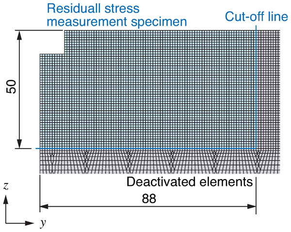
Numerical simulation model for redistribution of residual stress
Residual stress distribution in clad welds
The residual stress distribution in clad weld specimen was calculated by the procedure described in the previous section. The calculated temperature profile and residual stress distribution are compared with the experimental results.
Comparison of temperature profile
The maximum temperature distribution is shown in Fig. 10. The line of the maximum temperature of 1450°C well reproduces the fusion line observed by cross-sectional view shown in Fig. 11. The comparison of temperature profile between simulated and measured ones for thermocouple TC3 and TC4 is shown in Fig. 12. Thermocouples TC1 and TC2 were burned out or dropped off during the measurement. The thermocouples were located beneath passes 1 and 4, which were included in the weld residual stress measurement specimen. The temperature profiles obtained by the numerical simulation were in good agreement with the experimental results. Therefore, the result of the weld thermal cycle analysis has sufficient accuracy to be used as a thermal load in the following weld residual stress analysis.
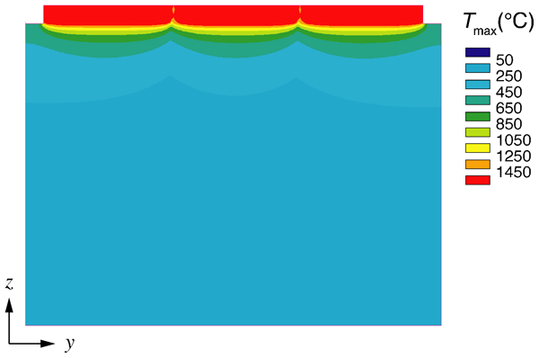
Maximum temperature distribution
Cross-sectional view of clad welds
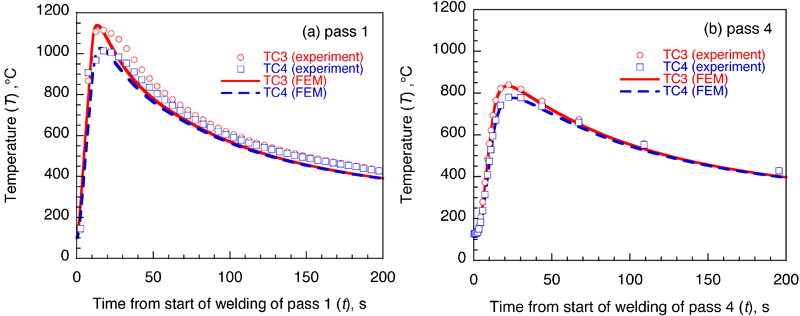
Comparison of temperature profiles between numerical simulation and experiment
Residual stress distribution
The residual stress distribution obtained by the numerical simulation is shown in Fig. 13. The residual stress in the transverse direction and longitudinal direction is shown in Fig. 13a and b respectively.
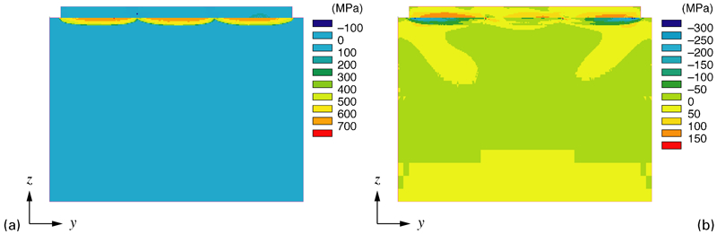
Calculated residual stress distribution in clad weld mock-up
In order to validate the result of the numerical simulation, a comparison with the result of X-ray residual stress measurement was performed. The specimen for the residual stress measurement was cut off from the fabricated clad welded joint; the redistribution due to cutting procedure was also calculated. The residual stress in the longitudinal direction of the mock-up was relaxed; therefore, the residual stress in the transverse direction is discussed in comparison with the experimental result. The distribution of the residual stress in transverse direction after cutting is shown in Fig. 14. Compared with the residual stress distribution before cutting shown in Fig. 13b, the redistribution of the residual stress is confirmed. The residual stresses obtained by the numerical simulation and the X-ray stress measurement along the line are plotted together in Fig. 15. The residual stress before and after cutting obtained by the numerical simulation are shown with lines, and the measured result is shown with point marks. The simulation result of the residual stress distribution in the specimen after cutting off was in good agreement with the X-ray stress measurement result: the numerical simulation has good accuracy to estimate the residual stress distribution in clad welds.
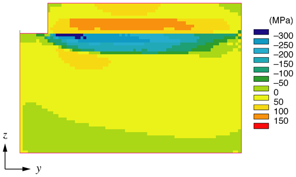
Calculated residual stress distribution in specimen after cutting off
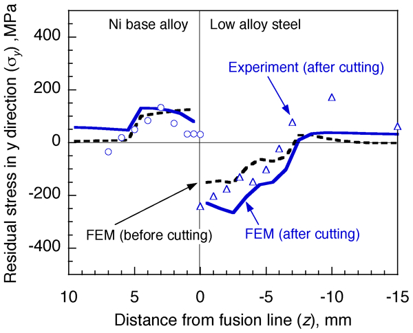
Comparison of residual stress distribution in residual stress measurement specimen between numerical simulation and experiment
Conclusions
In this study, a mock-up in which Ni base alloy was weld cladded over low alloy steel was fabricated, and the evaluation of the residual stress distribution by X-ray stress measurement method and finite element numerical simulation was conducted. The obtained results are summarised as follows:
The residual stress was measured even in coarsened Ni base alloy clad welds by X-ray stress measurement method utilising a two-dimensional detector and multiaxial rocking technique.
The residual stress distribution was well reproduced by the finite element simulation considering the redistribution due to cutting off of the specimen.
Footnotes
Acknowledgements
This study was partly supported by Priority Assistance for the Formation of Worldwide Renowned Centres of Research–The Global COE Program (Project: Centre of Excellence for Advanced Structural and Functional Materials Design) from the Ministry of Education, Culture, Sports, Science and Technology (MEXT), Japan, and by SCC mechanism collegium organised by Corrosion Centre of Japan Society of Corrosion Engineering, Japan.
This paper is part of a special issue from Eco-Mates 2011