
Abstract
For friction stir welding (FSW) of advanced high strength steel (AHSS) sheets with tensile strength grades between 590 and 1180 N mm−2, the appropriate welding condition range and the influence of welding conditions on microstructures and mechanical properties of the welds were investigated. The appropriate welding conditions to avoid defects such as the incomplete consolidation at the bottom of the weld were obtained for the steel sheets up to 1180 N mm−2 grade. The higher tool rotation speed evidently resulted in the larger volume fraction of martensite and higher hardness in the stir zone (SZ), attributed to an increase in the peak temperature of its thermal cycle. The tensile strength of the weld joint was as high as that of the base metal for the steels up to 980 N mm−2 grade, but slightly lower than that of the base metal for the steel of 1180 N mm−2 grade due to the heat affected zone (HAZ) softening.
Keywords
Introduction
Friction stir welding (FSW),1 a solid state joining process that enables the production of a high quality weld joint with less distortion, has been widely studied and increasingly implemented in industrial applications for materials with low melting temperatures such as aluminium and magnesium alloys.2, 3 However, the research and development of FSW for steels has progressed more slowly and remains at the early stage due to the limited durability of welding tool. In recent years, the developments of the tool materials have improved their durability and enabled the welding of steels in a laboratory scale. A number of studies have been reported on FSW of steels such as the interstitial free steel,4 carbon steels5– 13 and stainless steels.14– 19 Some of them especially detailed the FSW process for the ferrous materials, investigating the influence of the thermal history and the carbon content on the microstructures of the welds.10– 12
In the automotive industry, the application of the advanced high strength steel (AHSS) sheets to the car bodies has been conceived as a promising solution for the weight reduction. However, their use has been limited because of narrow appropriate welding condition ranges and poor mechanical properties of the weld joint, when they are welded with conventional welding processes. To promote the application of AHSS to automobiles, innovations of welding technologies are desired. FSW is considered as a promising solution and the research has been started for this objective.20
The authors studied FSW for high strength steel sheets with tensile strength grades between 590 and 1180 N mm−2. The appropriate welding condition ranges with no defect were clarified, and the microstructural features and mechanical properties of the weld joints were investigated.
Tested materials and experimental procedures
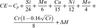
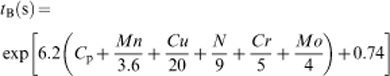
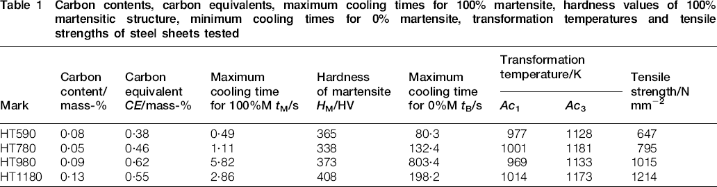
Four types of cold rolled steel sheets with the thickness of 1·6 mm and the tensile strength grade ranging between 590 and 1180 N mm−2 were used for the experiments. Table 1 shows their carbon contents (mass‐%), carbon equivalent values CE (mass‐%), predicted maximum cooling times from 1073 to 773 K necessary for fully martensitic transformation tM (s), predicted hardness values of fully martensitic structure HM (HV), predicted minimum cooling times from 1073 to 773 K for no martensitic transformation tB (s), predicted transformation temperatures Ac1 (K) and Ac3 (K), and tensile strengths (N mm−2). CE, tM, HM and tB were obtained with equations (1)–(4).21 The contents of alloying elements are given by mass fractions (mass‐%) in the following equations


Carbon contents, carbon equivalents, maximum cooling times for 100% martensite, hardness values of 100% martensitic structure, minimum cooling times for 0% martensite, transformation temperatures and tensile strengths of steel sheets tested
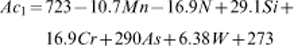
Ac1 and Ac3 were obtained with equations (5) and (6)
22
Microstructures of tested steel sheets
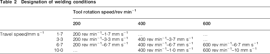
The butt weld joints with the length of 250 mm were produced with friction stir welding, having 3° of tilting angle of the spindle and controlling the tool rotation speed between 200 and 600 rev min−1 and the travel speed between 1·7 and 10·0 mm s−1. Table 2 denotes with symbols the variation of welding conditions in terms of the tool rotation speed and the travel speed. Figure 2 illustrates the welding tool used for the experiments, made of the tungsten carbide based material. It is noted in this report that the weld joints are distinguished across the weld line between the advancing side (AS), where welding direction is correspondent with the tool rotation direction, and the retreating side (RS), where the welding direction is opposite to the tool rotation direction.
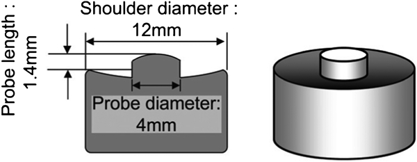
Illustration of welding tool
Designation of welding conditions
The weld joints were sectioned at three locations of 30, 125 and 220 mm from the weld start and optical metallography was conducted for those transverse sections to observe the defects and the microstructures of welds. The picric acid solution was used to identify the defects and the stir zone (SZ) boundary because it clearly categorises cementite or carbide so that the metal flow in the weld could be discerned through tracing them once aligned with hot rolling direction. The nitric acid solution in ethanol (nital) was used to characterise microstructures of the welds and identify the heat affected zone (HAZ) boundary since it clearly categorises the ferrite grain boundary as well as cementite or carbide.
To investigate the mechanical properties of the welds, the hardness and tensile tests were performed. The hardness test was carried out transversely across the weld at the mid‐thickness of the sheet using a Vickers hardness testing machine with 1·96 N load. Tensile test of the welds was conducted for the specimens with the geometry as shown in Fig. 3. The specimens were ground from the both surfaces and reduced to 1·0 mm in thickness to exclude the influence of surface condition and defects, if existed, of the welds.
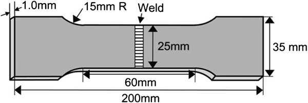
Geometry of specimen for tensile testing of weld joint
The thermal cycle during FSW was measured with type K thermocouple. The tip of the thermocouple was set at the bottom of the butt face and 100 mm distant from the welding start, using the welding fixture having a groove to guide the thermocouple, as illustrated in Fig. 4.
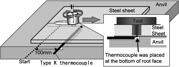
Illustration of experiment for thermal cycle measurement
Results and discussion
Investigation of appropriate welding conditions
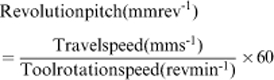
Figure 5 demonstrates the appearance of the representative weld produced by the experiment, indicating that the welds exhibited a fine and steady surface without defects. Figure 6 shows the macrostructures in the transverse sections for the welds of HT780, etched with picric acid solution. Incomplete consolidation that is the remains of the original butt interface due to inadequate stirring at the bottom was observed for some welding conditions, as indicated with circles in Fig. 6. Figure 7 shows the incomplete consolidations at higher magnification. When the tool rotation speed was 200 rev min−1, incomplete consolidation was not observed at condition 200 rev min−1–3·3 mm s−1 (Fig. 6a), while it was observed at condition 200 rev min−1–6·7 mm s−1 (Fig. 6b). When the tool rotation speed was 400 rev min−1, it was not observed even at condition 400 rev min−1–6·7 mm s−1 (Fig. 6c), but it was observed at Condition 400 rev min−1–10 mm s−1 (Fig. 6d). This tendency was considerably due to the reduction of the SZ size, caused by decrease in the heat input. For FSW of aluminium alloys, it has been reported that the heat input decreased with increasing the revolution pitch (mm rev−1) as expressed in equation (7)
23
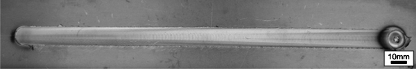
Appearance of representative weld produced by experiment (HT780, condition 200 rev min−1–3·3 mm s−1)
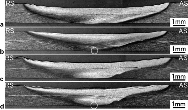
Macrostructures in transverse sections of welds of HT780, etched with picric acid solution
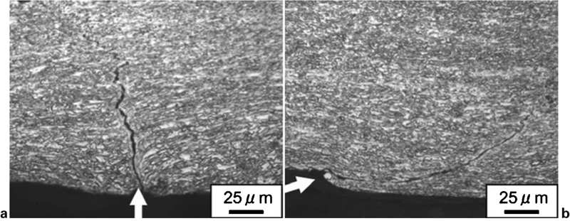
Incomplete consolidation observed in transverse sections of welds of HT780
The welding tool was deformed and damaged at the tool rotation speed of 600 rev min−1, due to the softening of its tungsten carbide based material. Higher tool rotation speed conceivably caused excessive frictional heat generation between the surfaces of the tool and steel sheets and exposed the tool to unfavourably high temperatures. Consequently, the appropriate welding condition range for HT780 was made clear in terms of the tool rotation speed and travel speed as shown in Fig. 8a.
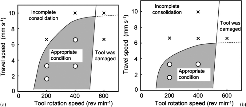
Appropriate welding condition ranges
In the case of HT1180, the appropriate welding condition range is shown in Fig. 8b. The incomplete consolidation was observed at condition 400 rev min−1–6·7 mm s−1, indicating the narrower appropriate condition range compared with HT780. This is conceived as follows. When the downward axial load is applied by the tool, a same scale of upward force is counteracted by the vicinities of the weld to sustain the tool. With increasing steel strength, the counteractive force is balanced with shallower insertion of the tool.
Influence of thermal cycle on microstructure and hardness of weld
Figure 9 shows the macrostructures etched with nital for the weld of HT780 at condition 200 rev min−1–3·3 mm s−1. The dark regions were supposedly heated above Ac1, experiencing the transformation during the welding thermal cycle. By superimposing this dark region with the region of SZ exhibited by picric acid solution etching in Fig. 6a, it is revealed that the welds can be divided into three regions: (1) the SZ; (2) the thermomechanically affected or HAZ above Ac1 (TMAZ/HAZ>Ac1); (3) the HAZ below Ac1 (HAZ<Ac1), as depicted in Fig. 9.
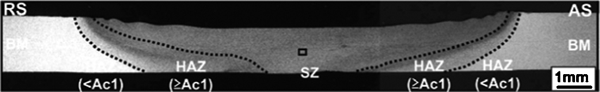
Macrostructures in transverse sections of welds of HT780, etched with nital (HT780, condition 200 rev min−1–3·3 mm s−1)
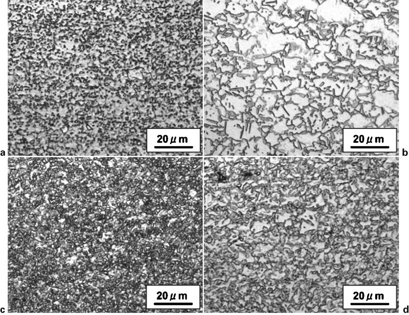
Figure 10 shows the microstructures in the centre of SZ indicated in Fig. 9 at conditions 200 rev min−1–3·3 mm s−1, 400 rev min−1–3·3 mm s−1 and 400 rev min−1–6·7 mm s−1. Figure 11 shows the hardness profiles in transverse sections of the welds at these three conditions. In SZ, the martensite and bainite were higher in volume fraction at conditions 400 rev min−1–3·3 mm s−1 and 400 rev min−1–6·7 mm s−1 than at condition 200 rev min−1–3·3 mm s−1. The average Vickers hardness in SZ at conditions 200 rev min−1–3·3 mm s−1, 400 rev min−1–3·3 mm s−1 and 400 rev min−1–6·7 mm s−1 were 255, 312 and 332 HV respectively. The hardness of SZ tended to be higher with increasing tool rotation speed. HM of HT780 is predicted to be 338 HV as shown in Table 1. Therefore, the microstructures in SZ at conditions 400 rev min−1–3·3 mm s−1 and 400 rev min−1–6·7 mm s−1 are predicted to be close to full martensite.
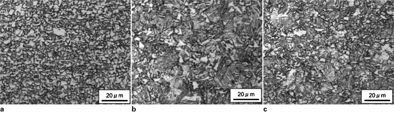
Microstructures in SZ of welds of HT780, etched with nital
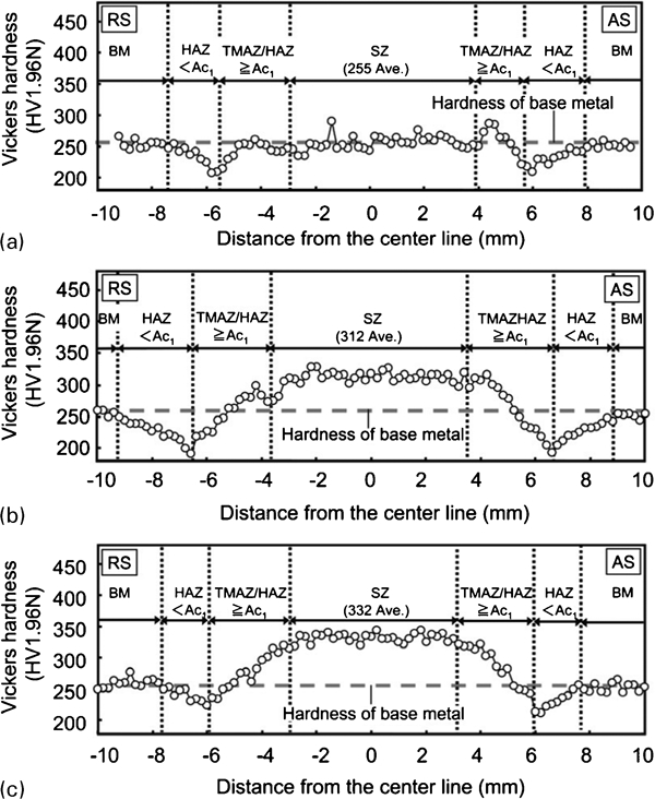
Hardness profiles in transverse sections of welds of HT780
The microstructure in SZ must be determined by the peak temperature and cooling rate. Figure 12 shows the result of thermal cycle measurement with the thermocouple set at the bottom of the butt at condition 400 rev min−1–3·3 mm s−1. The peak temperature was 1150 K and the cooling time from 1073 to 773 K was 2·84 s. In the case of HT780, Ac3, tM and tB are predicted to be 1181 K, 1·11 s and 132·4 s respectively, as shown in Table 1. This verifies that SZ at condition 400 rev min−1–3·3 mm s−1 was heated up to Ac3 and cooled with the cooling rate high enough for the martensite transformation. The earlier discussion that the tool was damaged at the tool rotation speed of 600 rev min−1 suggests that an increase in the tool rotation speed increased the temperature in SZ, assuming that the peak temperature in SZ was lower at condition 200 rev min−1–3·3 mm s−1 than at condition 400 rev min−1–3·3 mm s−1. Therefore, SZ at condition 200 rev min−1–3·3 mm s−1 was considerably heated to the two phase region of austenite and ferrite below Ac3 and only the austenite transformed to martensite or bainite during cooling, resulting in the smaller fraction of martensite and bainite (Fig. 10a) and the lower average hardness (Fig. 11a). In the case of condition 400 rev min−1–6·7 mm s−1, the cooling rate in SZ was considered to be higher than at condition 400 rev min−1–3·3 mm s−1, because of the higher revolutionary pitch. Consequently, SZ is more likely to transform to martensite (Fig. 10c) and has the average hardness as high as full martensite (Fig. 11c).
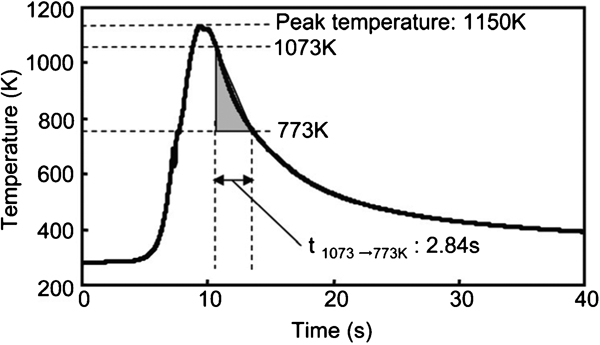
Thermal cycle of a weld of HT780 (condition 400 rev min−1–3·3 mm s−1)
As discussed earlier, the SZ size did not differ at the same revolutionary pitch, as well as the trend of hardness drop due to the tempering in TMAZ/HAZ>Ac1 and HAZ<Ac1 is also alike as seen in Fig. 11. However, the microstructures and the hardness in SZ were apparently different between conditions 200 rev min−1–3·3 mm s−1 and 400 rev min−1–6·7 mm s−1, even at the same revolutionary pitch. This is presumably because SZ, especially in the immediate vicinity of the tool, experienced different thermal cycles in terms of the peak temperature and cooling rate, although the net heat input to the entire weld was the same.
Mechanical properties of welds
Figure 13 shows the hardness profiles in transverse sections of welds of HT1180 at conditions 200 rev min−1–3·3 mm s−1 and 400 rev min−1–6·7 mm s−1. The hardness in SZ tended to be higher at condition 400 rev min−1–6·7 mm s−1 than at condition 200 rev min−1–3·3 mm s−1, as discussed for HT780 in the previous section. Moreover, the trend appears more obvious with HT1180. This is conceivably because HT1180, which has higher hardenability and carbon content, tends to transform to martensite and have harder martensitic structure and consistent with the results of the previous work for the FSW of carbon steels.11 It should be noted that the average Vickers hardness in SZ of HT1180 at condition 400 rev min−1–6·7 mm s−1 was 440 HV, which was higher than HM of HT1180 in Table 1. This may indicate that the strain introduced by the stirring process increased hardness in SZ, although further investigations are necessary to clarify the mechanism. In TMAZ/HAZ>Ac1 and HAZ<Ac1, the softened regions caused by tempering were seen and the minima of hardness were at the boundary between the two, i.e. Ac1, in the case of HT1180 as well as HT780. Furthermore, both the width of the softened region and the hardness drop from base metal was larger for HT1180. These dual phase steels consist of ferrite and martensite structures and exhibit the higher strength with increasing volume fraction of martensite. Therefore, the tempering enhanced the softening more significantly for the steels with higher strength.
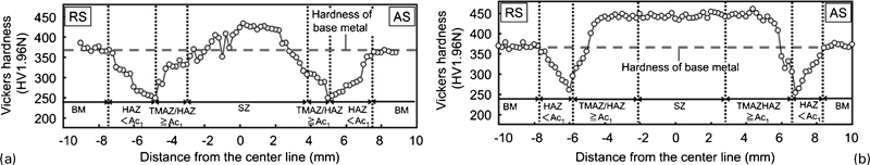
Hardness profiles in transverse sections of welds of HT1180
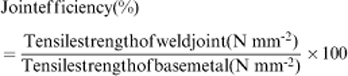
Figure 14 shows the relationship between tensile strengths of base metals and weld joints for HT590, HT780, HT980 and HT1180 at conditions 200 rev min−1–3·3 mm s−1 and 400 rev min−1–6·7 mm s−1. For HT590, the weld joints at both conditions were fractured at base metal and showed a tensile strength as high as that of the base metal. For HT780, HT980 and HT1180, weld joints at condition 200 rev min−1–3·3 mm s−1 were fractured at HAZ and exhibited 96, 95 and 84% respectively, of the joint efficiency (%) expressed in equation (8), while those at condition 400 rev min−1–6·7 mm s−1 were also fractured at HAZ and exhibited 99, 99 and 87% respectively, of the joint efficiency
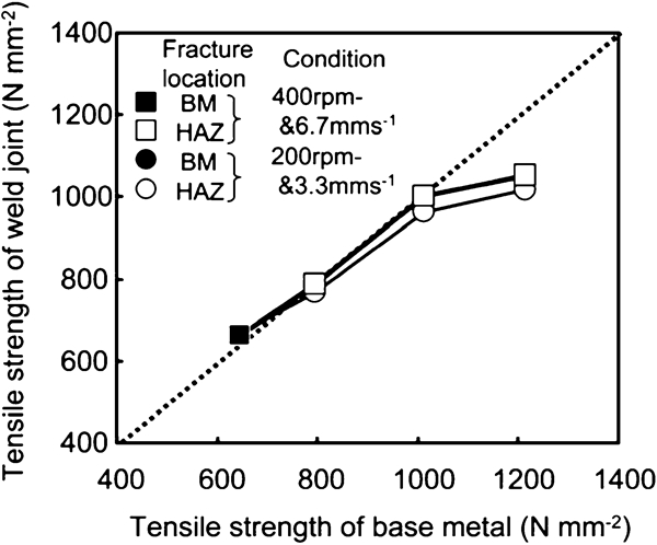
Relationship between tensile strengths of base metals and weld joints
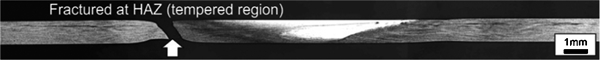
Location of fracture in transverse section of tensile specimen of HT1180 after testing (condition 200 rev min−1–3·3 mm s−1)
Moreover, for the weld joints of HT780, HT980 and HT1180, which were fractured in HAZ, the joint efficiency was slightly higher at condition 400 rev min−1–6·7 mm s−1 than at condition 200 rev min−1–3·3 mm s−1. This was considerably due to the effect of plastic constraint attained by the harder SZ and TMAZ/HAZ>Ac1 at condition 400 rev min−1–6·7 mm s−1.
Conclusions
Four types of AHSS sheets with the thickness of 1·6 mm and tensile strength grade ranging between 590 and 1180 N mm−2 were friction stir welded with various welding conditions. The influence of welding parameters on the occurrence of defect, the microstructure and the mechanical properties of the welds were investigated with respect to the type of steel and the thermal cycle during welding. As a result, the following conclusions were obtained:
The appropriate welding condition range was clarified for HT780 and HT1180, and tended to be narrower as the strength of steel was higher. The incomplete consolidation was prone to occur with increasing revolution pitch, i.e. with decreasing heat input.
The weld of FSW was divided into three regions: (1) the SZ; (2) the thermomechanically affected or HAZ above Ac1 (TMAZ/HAZ>Ac1); and (3) the HAZ below Ac1 (HAZ<Ac1).
The microstructure in SZ is affected by the cooling rate and peak temperature. The peak temperature in SZ is likely to have been significantly influenced by the tool rotation speed.
For the tensile tests of weld joints, HT590 was fractured at the base metal, while HT780, HT980 and HT1180 were fractured at HAZ and exhibited less than 100% of joint efficiencies, due to the softening in TMAZ/HAZ>Ac1 and HAZ<Ac1. It was suggested, however, that higher joint efficiency is attainable by optimising the welding conditions.