
Abstract
Modelling of welding distortion and residual stress has been an active research area since the late 1970s. Significant progress has been achieved since, especially in the areas of material modelling and investigation of three-dimensional geometries. This paper discusses some of the more recent developments in modelling residual stress and distortion and suggests issues for further research. The topics include, consideration of thermal transport in residual stress and distortion modelling, the development of applied strain methods for very large and complex structures, modelling of friction stir welding, sensitivity analysis and adaptive meshing.
Keywords
Introduction
Modelling of welding distortion and residual stress has been an active research area since the late 1970s. Some of the first publications in weld modelling include Refs. 1–4. Significant research in the 1980s includes the development of the ‘double ellipsoid’ heat input model by Goldak et al., 5 the modelling of phase transformations6– 8 and the use of three-dimensional (3D) shell models.9 Most of the weld modelling in the 1970s and 1980s involved two-dimensional (2D) models transverse to the welding direction using either plane strain or generalised plane strain conditions. Developments in weld modelling in the 1990s and 2000s included the use of 3D moving source models,10– 12 the development sensitivity formulations13, 14 and the development of the applied plastic strain method.15– 17
A detailed review of finite element modelling for welding residual stress and distortion modelling is available in Refs. 18–25. Typically, modelling of welding residual stress and distortion involves one way coupled thermomechanical analyses. Conductive heat transfer is considered in the thermal analysis using empirical models to apply the welding heat input. To consider the effect of the convective heat flow in the molten metal, artificially high thermal conductivity values are assigned for temperatures that exceed the melting point. Rate independent elastoplastic material response is considered in the mechanical analysis using the results of the thermal analysis as thermal load. Both thermal and mechanical analyses are typically performed using the finite element method in a Lagrangian reference frame.
This paper presents a review of current research trends of welding residual stress and distortion modelling. Issues for further research are suggested.
Consideration of thermal transport effects in welding residual stress and distortion
Typically, modelling of welding residual stress and distortion involves one way coupled thermomechanical analyses.16, 18– 20 Although thermoelastoplastic modelling of welding is reportedly computing residual stress in close agreement with experimental measurements, it is difficult to correlate the computed and measured fusion zones especially for high energy intensity processes such as laser and hybrid welding.26– 28
Thermal transport models of welding typically involve coupled heat and mass transfer and typically use computational fluid dynamics (CFD) solution methods in Eulerian reference frames. A viscoplastic material response is assumed in most thermal transport analyses of welding to eliminate the need for tracing and integrating the material response. As such, thermal transport analyses of welding result in zero residual stress and have primarily been used to model the temperature field and physical shape of the weld pool,29– 35 the interaction between arc and material,36 buoyancy, surface tension and magnetohydrodynamic effects.37 Computing residual stress requires modification of the constitutive model to account for the elastic component of stress which depends on the deformation history of each particle. Furthermore, if material evolutions, such as hardening or transformations are to be also considered in the computation of residual stress, the temperature, stress, strain and internal variable history of each material particle need to be computed.
In Ref. 38, a simplified approach has been implemented to evaluate the effects of thermal transport in the residual stress computation. A thermal transport analysis is performed first to compute the temperature history which is then used as loading in a conventional elastoplastic analysis to compute the residual stress. The thermal transport analysis is computed in an Eulerian reference frame using the commercial CFD code FLUENT.39 A gas metal arc welding (GMAW) and a hybrid GMAW/laser welding case are used as test cases where residual stress and distortion are computed by elastoplastic analysis using temperatures from conduction only and a conduction/convection (thermal transport) analyses.
For GMAW, both heat conduction and thermal transport analyses produced similar temperature, residual stress and distortion results, indicating that heat conduction modelling with the double ellipsoid model may be sufficient for modelling GMAW. For hybrid welding, the heat conduction and thermal transport analyses produced different temperature histories and distortion results (see Fig. 1), demonstrating the need for including thermal transport effects in modelling keyhole welding. However, the longitudinal residual stress results were in close agreement, suggesting that heat conduction analyses may be sufficiently accurate for computing residual stress even in keyhole welding. Further research is needed to evaluate the need for performing thermal transport analyses in residual stress for high energy density processes, especially for transverse and shear components.
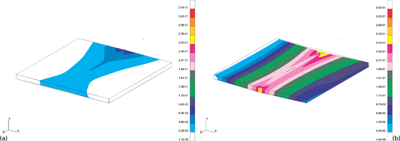
Hybrid weld plate deformation magnitude (mm, ×10)38
Applied plastic strain and fictitious weld load methods for very large structures
Thermomechanical modelling of weld distortion using moving source 3D models has been shown to compute all weld distortion modes accurately.16, 17 However, it has been proven to be computationally costly for large industrial applications such as heavy manufacturing and shipbuilding due to the temporal and spatial discretisation requirements for accurate prediction.40 Approximate methods, such as the applied plastic strain, and the fictitious load method, have been shown to be more cost effective.
The concept of applied plastic (inherent) strain was originally proposed by Ueda et al. 41 for determining the residual stresses and distortions of welded structures.42– 48 In their approach, six plastic strain components were simplified as two normal components, longitudinal plastic strain and transverse plastic strain, where the shear components were neglected. They determined the plastic strain distributions by both empirical and analytical methods.
Applied plastic strain methods involve using smaller actual welds models to determine the plastic strain resulting from welding and then mapping it to a full size 3D structural model. Early implementations of the method involved 2D weld models and 3D structural models applying the longitudinal plastic strain only.15 Later on, 3D models were proposed applying all six components of plastic strain.17, 49, 50
Michaleris et al. 17 evaluated the effectiveness and accuracy of 3D applied plastic strain methods by comparing the distortion results of the applied plastic strain analysis with those of 3D moving source simulations (see Fig. 2). Their conclusions are:
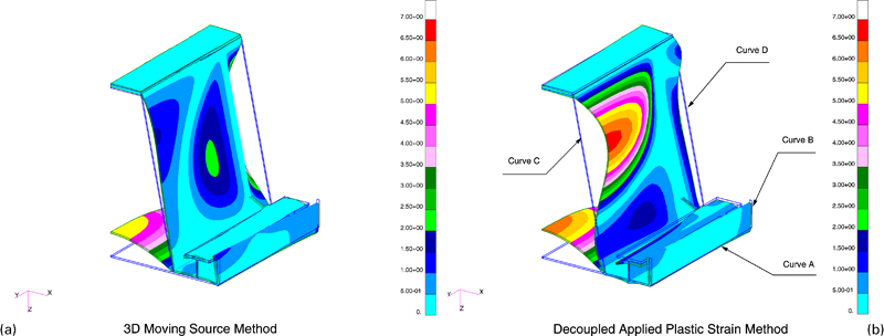
Distortion results of large structural model, large deformation analysis (from viewpoint 2, ×50 magnified)17
the 3D applied plastic strain accounts for all types of welding distortion. However, it is only qualitative in prediction angular distortion
the use of smaller models to compute the welding induced plastic strain does not consider the actual structural restrain of a large structure, and thus does not compute the actual plastic strain that would result from welding on a large structure
significant effort is required to implement the 3D applied plastic strain method. A complex structure needs to be decomposed to different joints which are individually simulated by welding analyses. Special algorithms are also needed to store and superpose the plastic strain components from each weld
further investigation is needed to incorporate tack welding and weld sequencing in the applied plastic strain methods.
Friction stir welding (FSW)
Modelling of FSW poses a considerable challenge due to the very large deformations involved in the process. If a Lagrangian reference frame is implemented, the large deformations result in severe mesh distortion and entanglement, necessitating continuous adaptive remeshing,51 which over time will lead to numerical errors. Typically, for problems exhibiting very large deformations an arbitrary Lagrangian–Eulerian (ALE) approach is used instead of a pure Lagrangian to minimise the error caused by the mesh distortion.52– 57 An advantage of ALE approaches for modelling FSW is the capability to model transient effects, tool plunge and tool removal and tool contact with the material. However, all current ALE models of FSW require adaptive remeshing that over time introduces numerical errors.55
Owing to the difficulty of dealing with mesh distortion, most investigators using a Lagrangian modelling approach ignore the material flow and instead assume that stress and deformation in FSW are caused by thermal expansion only.58– 62 The temperature distribution is provided by either a pure conduction analysis using a distributed heat input model or a CFD analysis of the stir zone.63, 64 These models are similar to the elastoplastic models used in modelling residual stress and distortion in arc welding and are typically used to compute residual stress and distortion in FSW. However, they cannot provide an insight into the material flow and stress around the spinning tool.
The significant material deformation and entanglement in FSW make an Eulerian reference frame a more suitable alternative than a Lagrangian frame since in an Eulerian frame, the material is not attached to the mesh but it rather flows through it. Therefore, there is no issue with mesh entanglement as in a Lagrangian mesh. Early research using Eulerian frames for material processing includes modelling drawing and rolling processes.65, 66 The constitutive model used in an Eulerian model can have a significant effect on the modelling effort. If a history dependent response model is used such as an elastoplastic or elastoviscoplastic, it is necessary to compute the deformation history of each particle in order to determine stress and strain. This can be accomplished by either computing the streamline of each particle67– 69 or by computing material evolution in a weak finite element (mixed) formulation.67, 70, 71 The streamline integration methods for elastoplastic or elasoviscoplastic models do not allow for the computation of global algorithmic Jacobian (tangent stiffness) leading to convergence difficulties. On the other hand, the mixed finite element formulations lead to systems with large number of degrees of freedom. Owing to these modelling difficulties, most investigators neglect history evolution in Eulerian models by assuming pure viscoplastic material response, which is a typical CFD approach.63, 64, 70, 72– 74 Such material models may be sufficient at the high temperatures and strain rates near the stirring zone. However, they are not appropriate for lower temperatures and result in zero stress at regions away from the tool. This is erroneous since the higher yield strength and elastic modulus at lower temperatures along with accumulated elastic strains result in high stresses.60, 75
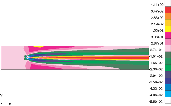
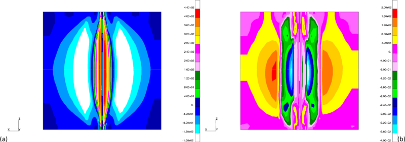
Qin and Michaleris developed a velocity based Eulerian elastoviscoplastic formulation for modelling processes with very large deformations. The formulation was demonstrated in a 2D Eulerian model of FSW71, 76– 78 and was verified by comparing computed residual stress against experimentally measured data (see Fig. 3). The approach can accommodate elastoviscoplastic material response and model the material flow in FSW by using velocity as a primary variable without the need of adaptive meshing as it is needed in displacement based ALE formulations.52, 55– 57 Both frictional heat and plastic deformation heat generation are considered and the effect of both thermal expansion and mechanical deformation due to material spinning are accounted in the calculation of stress and deformation. The friction stir implementation of Qin and Michaleris76, 77 is limited by the use of a 2D model only. Further work is also needed to extend this formulation to transient analyses and therefore investigate start and stop of welding and unsteady effects during the process. Finally, additional work is also needed to consider updating the analysis domain to account for the motion of traction free surfaces.
Contour plot of longitudinal residual stress in FSW (MPa)76
Sensitivity analysis
Sensitivity analysis has been widely used in many design optimisation problems.79– 83 Sensitivity analysis can be performed by analytical or by finite difference techniques.84 The analytical methods are more accurate and computationally more efficient than the finite difference method. The analytical sensitivities can be computed either by direct differentiation or by the adjoint method.80 For transient problems, the direct differentiation method is algorithmically more efficient than the adjoint method.85
Sensitivity analyses for thermoelastoplastic and welding problems have been developed in Refs. 13, 14 and 86–88. In Ref. 88 sensitivity analysis is used to optimise the thermal tensioning process to minimise welding residual stress and distortion (see Fig. 4). Mishra and DebRoy30 used sensitivity analysis in identification approach to compute unknown material and model parameters in thermofluid modelling of welding. Recently, sensitivity analysis has been gaining attention as an uncertainty quantification method in the nuclear industry. Figure 5
Longitudinal residual stress and its sensitivity with respect to side heat source (MPa)88
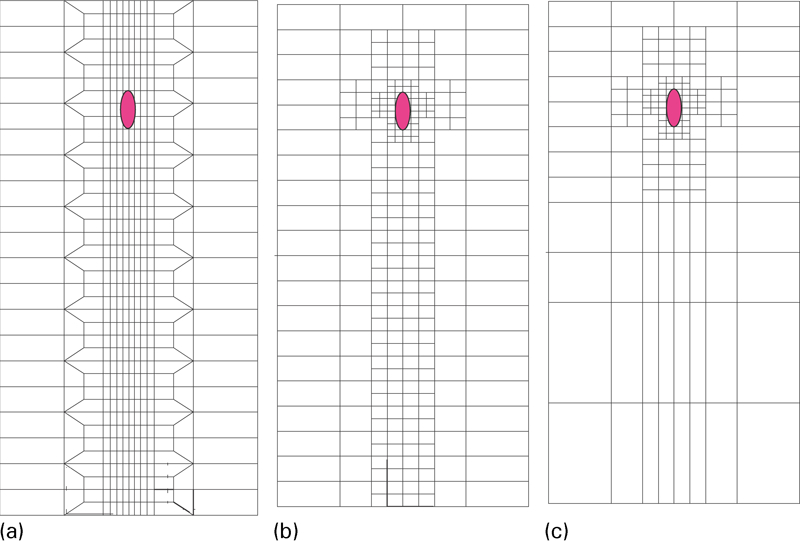
Illustration of static and adaptive meshing methods in weld modelling
Adaptivity
Most commercial finite element codes suitable for weld modelling (ANSYS and ABAQUS standard) use static meshing (Fig. 5) which has to be manually refined over the entire weld path before the analysis commences. As a result, even with steadily increasing computational capabilities, performing 3D welding residual stress simulations is a time consuming task involving labour intensive mesh generation to capture fine temperature and stress gradients near the weld, and lengthy computer runs. Adaptive meshing can allow the use of an initially coarse mesh which will be automatically refined or coarsened depending on the solution. Typically, adaptivity is implemented in isotropic manner, where elements will be refined or coarsened in all spatial directions simultaneously. However, in welding, isotropic adaptivity only leads to refinement due to the plastic strain accumulated over the weld zone.89 The application of anisotropic adaptivity in modelling welding has been explored in Refs. 90 and 91 and significant computational savings are reported in 2D implementations. Further work is needed in the implementation of anisotropic adaptivity in 3D weld simulation.
Conclusions
This paper discusses some of the more recent developments in modelling residual stress and distortion. The following topics are suggested for further research.
Consideration of thermal transport in residual stress and distortion modelling. Further research is needed to evaluate the need for performing thermal transport analyses in residual stress for high energy density processes, especially for transverse and shear components.
Applied strain methods for very large and complex structures. Further development is needed to incorporate tack welding and weld sequencing in the applied plastic strain methods.
Modelling of FSW. Further work is needed to develop 3D transient thermoelastoviscoplastic Eulerian models. Additional work is also needed to consider updating the analysis domain to account for the motion of traction free surfaces.
Sensitivity analysis. Further research is needed in implementing sensitivity analysis in uncertainty quantification of welding residual stress with respect to processing, material and geometry parameters.
Adaptive meshing. Further work is needed in the implementation of anisotropic adaptivity in 3D weld simulation.