
Abstract
This work investigates the weldability of Inconel 718 using the metal inert gas (MIG) welding process called ‘cold metal transfer’. This arc welding process is reported for working with a lower heat input compared to other arc processes. The consequences are less base metal impaired, low deformation and low residual stress level in assembly. In order to check these abilities, metallographic, texture, chemical and residual stress analyses have been carried out. Results show that MIG cold metal transfer has good properties for the welding of Inconel 718 inasmuch as no defect has been detected and a lower level of residual stresses has been introduced in metal compared to classic MIG.
Keywords
Introduction
Inconel 718 is a nickel base superalloy, 1 1,2 which is widely used in the aerospace and energy industries because of its high mechanical resistance to corrosion. It is strengthened by the precipitation of γ″ precipitates. Its welding is greatly used in the manufacturing process or for repairing worn or broken pieces. This alloy is usually welded with tungsten inert gas (TIG) process, which induced in a general way large heat affected zone (HAZ), deformation and residual stresses, which can affect sizing and production. In order to reduce these harmful impacts, new processes derived from metal inert gas (MIG), or gas metal arc welding, have been developed to reduce the heat input. Usually, the main innovations come from the optimisation of the welding electric signal.3– 5 The process chosen for this study is the MIG cold metal transfer (CMT) developed by Fronius Company, which combines a control of the welding electric parameters and a wire motion control at the same time. It works in the short circuit domain,6– 8 which means low welding energy. The major evolution compared to pulsed MIG is the integration of the motion wire control into the welding cycle. Wire feed speed, intensity and voltage are linked and controlled by a microprocessor. When short circuit occurs, intensity and voltage are turned to zero, while metal droplet is deposited thanks to the wire forward without electric arc. Thus, the metal transferring into the weld pool does not need pinch effect, which requires high intensity; therefore, heat input, spatter, fumes and sound level are lower than classic MIG. Hence, MIG CMT is able to produce welds with low geometrical deformation9 and low residual stresses,10 especially on aluminium, for which it has been designed. Previous studies have been published about the welding of aluminium, zinc coated steels, heterogeneous aluminium–steel welding8,11– 15 and iron cladding on aluminium,13 but no study is available regarding the welding of nickel based alloys. The aim of this work is to study the ability of MIG CMT applied on Inconel 718 through the analysis of the microstructure and the residual weld stresses.
Material and experimental techniques
Weld bead was made using the MIG CMT process, and the studied sample was extracted from there. The substrate was a 6·5 mm thickness plate of Inconel 718 (in solution then annealed condition). The 1·2 mm diameter wire used for the weld was Inconel 718. The weld speed was 0·3 m min−1, and the wire speed was 4·5 m min−1. The shield gas was composed of an argon base with 5% hydrogen, and the flow was 15 L min−1. The plate was clamped during the operation and the cooling duration. No further heat treatment was carried out on the piece after the welding.
The cross-section of the sample was first characterised by using light optical microscopy after mechanical preparation following chemical attack (Kalling reagent).
The chemical analysis was performed using energy dispersive spectroscopy (EDS) measurements in the base material, HAZ and weld zone. An Oxford Instrument probe equipped on a field emission gun SEM (MERLIN, Zeiss) was used to do the experimentations.
The as welded sample was examined using SEM and electron back scattered diffraction technique (EBSD). Before the analysis, the sample was mechanically and then electrochemically polished with a Struers A2 solution adapted for nickel alloys, at 20°C, with a tension of 45 V during 12 s. The EBSD data were obtained with a field emission gun SEM (Zeiss) and processed with orientation imaging microscopy software.
Residual stresses were determined with a non-destructive technique by using neutron diffraction carried out on a dedicated two-axis G5·2 diffractometer at Laboratoire Léon Brillouin. A constant wavelength of 0·287 nm was used, allowing recording {111} diffraction peak of face centred cubic phase, the gamma phase, i.e. the matrix, at diffraction angles close to 90°, for a better spatial resolution. Strains were measured along three principal directions (longitudinal, transverse and normal) defined by considering the geometry of the linear bead (Fig. 1). Measurements were carried out at several locations (Fig. 2) with respect to the centre of the bead (transverse scan up to 6 mm away at a fixed depth of 1 mm below the upper surface) and at the centre of the weld at three different depths (1, 2 and 3 mm). In order to respect the hypothesis for applying Hook's law, i.e. isotropic structure and mechanical properties, measurement positions (Fig. 2) were chosen in the microstructure area showing equiaxed grains. Moreover, in the melted zone, the presence of large elongated grains and texture effects (morphological and crystallographic) prevented the authors from measuring the diffraction peaks along principal directions. A gauge volume of 1×1×5 mm was defined using Cd slits with a 5 mm aperture along the axis of the bead (to improve intensity) when possible (i.e. for transverse and normal measurements only). For longitudinal measurements, a sampling volume of 1×1×1 mm was used.
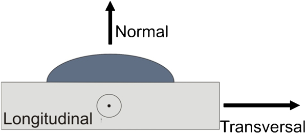
Considered principal directions for strains in bead
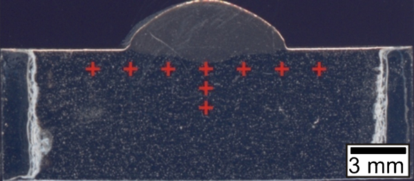
Neutron diffraction measurement locations of residual stresses under bead
The unstressed reference lattice spacing d0{111} required for strain calculations was obtained from measurements performed on the base material.
Triaxial residual stresses were calculated from the measured strains by applying Hooke's law

The macroscopic values for Young's modulus and Poisson's ratio were used, i.e. E = 210 GPa and ν = 0·33 for Inconel 718.
Results
Macrostructure analysis
Before advanced investigations, a macrographic analysis was carried out to determine the different areas forming the weld. Figure 3 shows a macrography of the weld section. The weld bead is characterised by low penetration (0·7 mm max.), especially near both sides, where there could create a defect resulting from the lack of fusion. This penetration profile is due to the narrow arc produced by the CMT process, which focuses energy at the centre of the bead. The HAZ corresponds to the white strip, and the width is inferior to 0·5 mm (Fig. 3), which is usually three times lower compared to TIG arc welding.
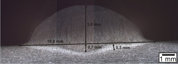
Macrography of bead cross-section
Microstructure
Figure 4 shows the EBSD maps obtained in the middle of the weld. Two main microstructures can be observed. The parent metal at the bottom is made of small equiaxed grains characteristic of a hot rolled sheet, while at the top, the weld zone is characterised by columnar grains. This typical structure is formed during the solidification stage. The growth of the crystallites follows the temperature gradient and creates extended grains. The average length of these grains reaches 120 μm long, while the average dimension of the substrate grains reaches 12 μm.
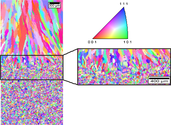
Map (EBSD) of middle of weld zone including zoom in weld zone limit: distribution of {hkl} planes parallel to observation plane
To conclude with the microstructure analysis, the absence of the lack of fusion was checked. The EBSD analysis was also carried out on the weld edges. Figure 5 shows the EBSD map in the left corner of the weld. No defect is visible, and the quality of the fusion line is correct. The multicolour points on the left side of the weld come from the lack of indexation. However, no crack or lack of fusion was found after SEM investigations on this area.
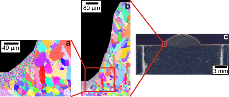
a, b maps (EBSD) of left weld edge with its position on c macrography
Chemical analysis
The chemical composition of the bead was studied. The chemical composition across the bead was measured with EDS, i.e. from the parent metal to the weld zone top. Figure 6 shows the evolution of composition in the bead. No critical evolution of the composition is visible. There is no significant loss of element during the welding, which means that the weld has the potential to recover a maximum of the mechanical properties after the heat treatment.
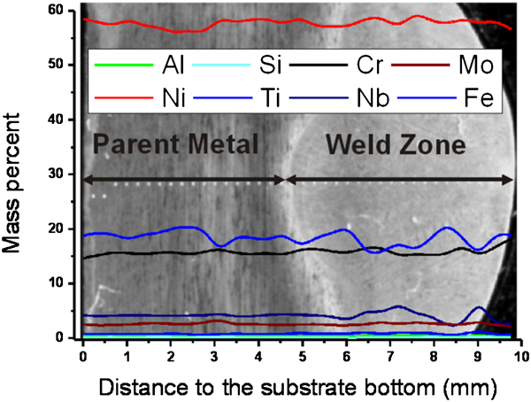
Evolution of chemical composition through beads
Figure 7 shows an SEM image of the bead toe obtained with the secondary electron detector. The precipitates appear as white dots. The melted zone is delimited by the red dashed lines. Two kinds of precipitates are present. Large precipitates (∼10 μm) are located in the base material and the melted zone. They are carbides currently met in the Inconel 718. 1 2 1,2,16 The second kind of precipitates is exclusively dispersed in the entire weld zone, and their size is ∼1 μm.
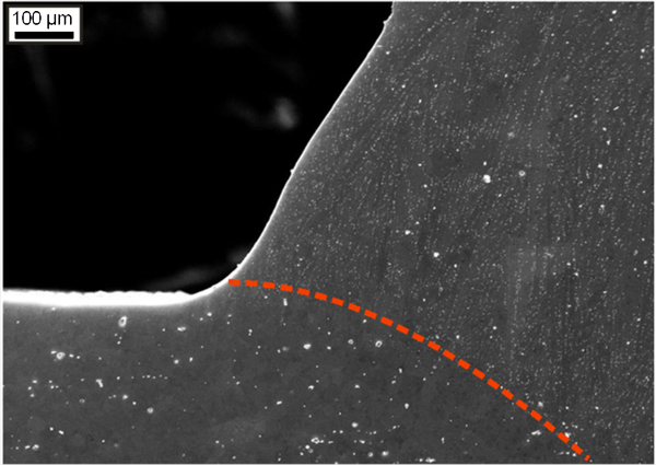
Secondary electron image (SEM) of weld toe
Figure 8 shows an EBSD image quality index map focus on the limit (red dot line) between the weld zone and the HAZ from Fig. 5b (weld toe area). The software applies to each studied area a pixel in greyscale, which informs about the Kikuchi diffracted pattern quality. Therefore, when the quality is poor, the associated pixel becomes black. This map illustrates the specific distribution of the small precipitates in the melted zone. The boot shaped grain has two parts. The lower part belongs to the substrate, and the upper part belongs to the weld zone. Therefore, in the same grain, two microstructures can be observed. One is free of precipitates, while the other contains particles. This figure illustrates the grain's growth, which occurred by epitaxy from the substrate crystallites. Indeed, the red dot line limit, separating the two parts, coincides with the upper surface of the plate.
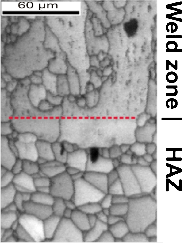
Limit between precipitate and no precipitate zone
According to the EBSD analysis, the particles are arranged in lines parallel to the 〈100〉 crystallographic direction from the hosting grains. The 〈100〉 crystallographic direction is the preferential solidification direction of Inconel 718.
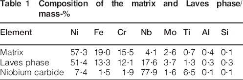
A high magnification picture of the melted zone is shown in Fig. 9. Three phases are visible. The dark grey phase corresponds to the matrix. The white particles are precipitates of ∼1 μm visible, and they are visible on the weld zone in Fig. 7. The third phase surrounds the white particles. Additional EDS analyses have been performed to characterise these phases. The analyses show that the white particles contain a high amount of niobium and that the third phase is an intermetallic compound. Its composition is given in Table 1. These phases have been already reported in the literature.17– 19 This kind of white particle is reported to be niobium carbides associated with the Laves phase (surrounding phase). Therefore, apparently, the aligned white particles visible in Figure 8 Figs. 8 and 10 are niobium carbides associated with the Laves phases.
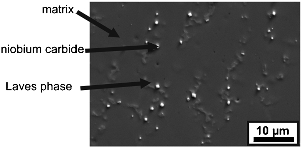
Secondary electron image (SEM) of weld zone
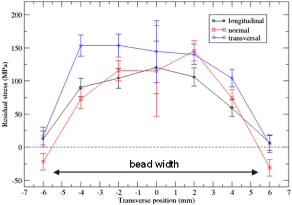
Residual stress profiles under bead in transverse scan measurements along three principal directions
Composition of the matrix and Laves phase/mass-%
Residual welding stresses
The MIG CMT is a welding process known for producing lower deformations and thus lower residual stresses in the welds compared with the other classic arc welding techniques. 9 9,10 One of the aims of this paper is to check this ability applied to Inconel 718.
Figures 10 and 11 show the residual stresses profiles in the transverse and depth scans. The tendencies are similar whatever the studied directions. Regarding the transverse scan below the surface (Fig. 10), stress tends towards the highest tensile values at the centre of the bead, with maximum values between 150 and 200 MPa, and then tends to zero values away from below the bead. In the vicinity of the centre, the mechanical state is close to a triaxial isotropic tensile stress state behaviour, i.e. like a negative pressure state.
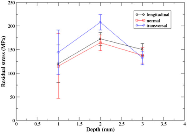
Residual stress profile: in-depth scan at centre of bead
Concerning the thickness scan profile (Fig. 11), higher values at 2 mm depth can be observed especially along the transverse direction, where it reaches ∼200 MPa. The normal stresses show a peak of ∼150 MPa (14% of Inconel 718 Rp0·2) at 2 mm depth. This stress configuration is unfavourable for the fatigue strength of the weld. However, the value is small compared to the yield stress of the alloy.
The important uncertainties obtained at the centre of the bead and at 1 mm depth are due to the fact that the measurement point is located very close to the melted zone. The microstructure is probably far from homogeneous within the gauge volume, and this should affect the quality of the diffracted signal.20
The residual stress values must be interpreted considering that the sample is as welded, and thus, no heat treatment or relaxing operation has been carried out. Moreover, the bead was made at the surface of a plate and not to join two pieces as usual welding. It induces that the material is self-constrained and has less freedom to adapt itself to the strain than a composed element. Globally, the results show that the residual stresses induced by MIG CMT are much lower compared to classic gas metal arc welding used on the steel plate. 21 21,22 Considering the residual strains or the residual stresses, the literature confirms this trend. 10 10,11
Discussion
The MIG CMT process uses a cold arc that induces low penetration. However, no lack of fusion has been found, especially on the weld toe. This fact indicates that the process is energetic enough despite a relatively low temperature to assure good joining. Moreover, the weld toe EBSD map in Fig. 5 shows the epitaxial grain growth from the sheet plate that promotes the welded liaison quality.
The HAZ length is reduced compared to the classic arc welding process, such as TIG. Moreover, no defect is visible in this area. Therefore, it means that the parent metal is not much affected, and thus, all the other things being equal, the mechanical properties of the weld are better than with a classical welding.
Chemical analyses have been performed on the different phases present in the weld zone. The white precipitates are niobium carbides, which are present with intermetallic phase. This phase is known as eutectic Laves phase in the literature.17 The presence of the Laves phase with carbides is reported in Ref. 17 and belongs to the metallurgy of Inconel 718.16, 18, 19 Their presence in the interdendritic spaces indicates that they are formed and solidified during the last stages of solidification. Their formation is reported in Ref. 19. Niobium carbides are produced from the liquid phase between 1280 and 1265°C. At 1160°C, niobium carbides and liquid reacts to form eutectic Laves and γ (matrix). It occurs in the last liquid space, i.e. in the interdendritic spaces. That is why these structures present in the grain boundaries and inside the grains are mainly oriented according to the preferential direction of solidification 〈100〉. Their formations have detrimental effects about the weld strength. Indeed, these low melting compounds could induce cracks in the HAZ during cooling. Moreover, Inconel 718 is strengthened by the precipitation of γ″ (Ni3X with X = Nb, Ti or Al); now, the niobium carbides compete in terms of element alloy consumption with γ″ precipitates. Therefore, it could lead to a lower concentration of γ″ due to the depletion of alloying elements and thus lower mechanical properties. Moreover, the brittle behaviour of carbides can also promote cracking.18 However, no crack has been noted during the analyses. Furthermore, it should be remembered that the sample did not receive heat treatment after welding. This step is usually performed to remove partially or completely the phases that decrease the mechanical properties. Therefore, a new study is planned on heat treated samples in order to characterise the remaining phases.
The characterisation of residual welding stresses showed that their level is low (14% of Rp0·2). These are tensile stresses, with an almost isotropic triaxial state, which are mainly located below the bead. These tensile stresses appear during the cooling, when the thermal gradient induces differential dilatations between the different zones of the weld. Moreover, the solidification creates withdrawal forces in the melted zone, which pulls on the parent metal. These two phenomena are responsible for the tension state of the base material under the bead. This kind of stress is detrimental for the fatigue behaviour of the weld because they promote crack propagation. However, their low level before heat treatment suggests that they will not have a large influence on the fatigue behaviour of the bead and that they are likely to relax, at least partially, during the post-weld heat treatment. This state is consistent with a localised withdrawal at the surface of the plate during the solidification of the bead. It can be supposed that the welding configuration in the present study is not similar to the classic joining between the two plates (butt weld). Indeed, depending on the flanging, in the classic joining, the plates could deform to adapt themselves to the stresses. In this case, the stress level is lower, but the assembly is deformed. In the configuration in this study, the melted zone is in the middle and at the surface of the plate, and stresses cannot be reduced by deformation because during the solidification, the bead is stuck on each side by a solid metal, and so, it induces a higher level of residual stresses. A further study will be performed considering a butt weld configuration in order to assess geometry effects, mainly on the resulting mechanical characteristics.
Conclusions
The abilities of the CMT process have been studied on Inconel 718. In a first approach and for the sake of clarity, a single bead configuration has been studied. The microstructure, the chemical composition and the residual stresses of the as welded sample have been analysed.
The microstructural analysis has demonstrated that the weld quality is correct: no lack of fusion is present. In other terms, the ‘cold’ process produces enough energy to assure metallurgical liaison. The HAZ size is small (0·5 mm) compared to classical MIG welding. The size and geometry of crystallites in the weld zone, i.e. large dendrites, are similar to the classic MIG process. These characteristics could be modified considering the thermal history, i.e. preheating or assisted cooling. However, brittle phases (Laves phase and niobium carbides) are present in the weld zone.
The EDS chemical analysis has shown the homogeneity of the weld bead. No significant variation is visible, which means that the mechanical properties of the material can be potentially fully restored after heat treatment. The EDS has also characterised the others phases present in the weld zone. It has been determined with the bibliography that they are Laves phases and niobium carbides. Regarding the residual stresses, the measures confirm the results of previous works performed on other metals, i.e. lower values of stress inside the as welded material with the classic arc welding process.
Although CMT produces beads that appear similar to the classic MIG weld, some intrinsic properties of the weld are improved due to the relatively low process temperature. Actually, the improvements in HAZ size and residual stress level are the most interesting for increasing of the weld quality. Moreover, this work demonstrated that CMT is fully adapted to the welding of Inconel 718.