
Abstract
The excellent corrosion resistance of low carbon vacuum melted 316 stainless steel coupled with its non-magnetic properties makes it ideal for biomedical applications. The typical joint geometry for microcomponents, such as medical implants, includes joining of fine wire to a larger block. However, this type of joint has received little attention in the current literature. The present study was conducted to examine the microstructure and mechanical properties of low carbon vacuum melted 316 stainless steel wire welded to a larger block. Results revealed solid state bonding occurring at low currents, while fusion bonding occurred at higher currents. This was due to the highly asymmetrical heat generation resulting in almost complete melting of the wire before the initiation of interfacial melting. This is a distinctly different bonding mechanism compared to previous studies on crossed wire joints.
Introduction
Stainless steel is ideal for implantable medical device applications due to its high corrosion resistance and non-magnetic properties. Several different joining methods can be used to fabricate such components, each offering different advantages. Resistance welding is a popular welding process due to its high speed and low cost combined with excellent reproducibility, also making it suitable for joining small scale components. In application, joint sizes typically range from millimetres to micrometres, and resistance joining of such small scale components is referred to as resistance microwelding (RMW).
Although RMW is a widely applied joining process, only limited literature exists that details its application for medical devices. The RMW of Ni and Au plated Ni sheets and wire has previously been investigated,1– 3 and it was shown that the low resistivity of Ni compared to stainless steel impeded the creation of a fusion joint. Fusion bonding requires the interface temperature to exceed the workpieces’ melting temperature, thereby creating a fusion bond. Khan et al. 4 presented a detailed study of resistance crossed wire (wire to wire in a crossed configuration) welding of fine low carbon vacuum melted (LVM) 316 stainless steel wire. They showed a transition from solid state to fusion bonding with increasing current and/or reducing electrode force, which thereby increased heat generation in the weld. Optimal weld configuration was found to create sound joints with smooth surfaces and high strength (∼70 N) suitable for biomedical applications.
In microsize medical or electronic devices, joints are often made between components of considerably different geometries and sizes. A common example is the joining of a fine wire to a larger block or connector. Owing to the fact that miniature workpieces themselves generate and conduct both heat and current, the relative size and geometry of the workpieces can severely affect the outcome of the RMW process. Downscaling implies relative changes in the interface area/bulk ratio and the total heated material volume. The heat balance is further complicated by an asymmetric weld configuration. Current research has focused primarily on symmetrical weld configurations, such as cross-wire and resistance spot microwelding of identical workpieces.1, 4– 6 Current literature lacks details on the effect of welding dissimilar workpiece geometries with microscale dimensions. Hence, the purpose of the present study was to investigate the RMW of 316LVM stainless steel wire to a block of the same material. Furthermore, results have permitted comparing the bonding mechanism to that of cross-wire welding. This has been achieved by characterising and determining the welding and bonding mechanisms as well as the final strength and microstructure of the bonds.
Experimental
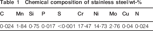
Welds were produced by resistance welding medical grade stainless steel LVM wire (0·4 mm) to the surface of a block (3×3×6 mm) of the same material using round RWMA class 2 (Cu–Cr) flat ended electrodes with 3·2 mm face diameter. Both wire and block were used in the as received condition with only the surfaces being cleaned in acetone before welding. The material chemical composition is given in Table 1. A MacGregor DC400P direct current controller and a Unitek 80 A/115 V weld head (Miyachi Unitek Corporation, Monrovia, CA, USA) were used. Two levels of the weld force (25 and 49 N) were examined. The welding current was varied with 100 A intervals ranging from the initiation of a bond (200 A) to overwelding (600 and 800 A for 25 and 49 N weld force respectively), resulting in severe joint deformation. The weld schedule comprised of a 1 ms current upslope, 50 ms weld time and 3 ms downslope.
Chemical composition of stainless steel/wt-%
The tensile test set-up was conducted using an Instron 5548 microtensile tester. A 500 N load cell with ±0·4% accuracy was used to measure the breaking force at a pull speed of 10 mm min−1. The welding and tensile test set-ups are shown schematically in Fig. 1a and b respectively. In addition, the locations for the two types of failure modes identified as ‘interfacial fracture’ and ‘failure in wire’ are shown. ‘Interfacial fracture’ indicates fracture occurring through the weld interface, completely separating the wire and block. ‘Failure in wire’ implies fracture travelling through the heat affected region, thereby leaving part of the bonded wire attached to the block.
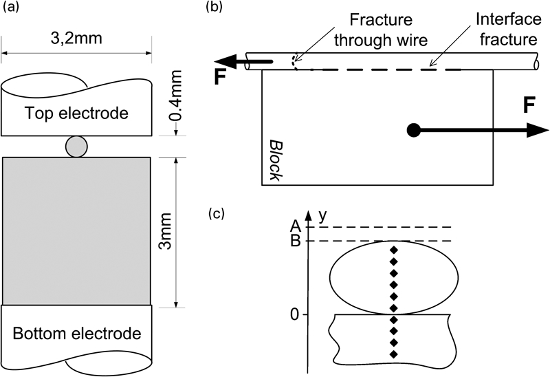
a weld set-up, b joint breaking force (JBF) test set-up and c setdown and hardness set-up
Cross-sections of the welds were observed using optical microscopy; specimens were etched using 5 mL HNO3, 25 mL HCl and 30 mL H2O at an elevated temperature of 80°C for 3–5 s. As illustrated in Fig. 1c, the collapsed height B of the wire with original height A was quantified by the measured setdown A–B of the top electrode during the weld. Hardness testing was conducted on a Shimadzu microhardness tester (Shimadzu Corporation, Kyoto, Japan) with a 10 g load held for 15 s. The hardness profiles were made through the wire and interface region, as also illustrated in Fig. 1c.
Results and discussion
Tensile shear testing of joint strength
The welding parameters were chosen with offset in the parameters used by Khan et al. 4 for cross-wire microwelding. Trial welds showed that higher current levels were needed to achieve bonding in wire block welds compared to cross-wire welding. The measured electrode setdown and joint breaking force (JBF) for 25 and 49 N weld force as a function of weld current are shown in Fig. 2. The JBF for joints welded at 200 A could not be tested since the weak bonds fractured upon clamping in the tensile testing machine. For the 49 N weld, force bonding was found to initiate after 200 A and increase in strength up to 600 A. Welding currents above 800 A caused ‘overwelding’, where high energy inputs induced weld defects (i.e. excessive melting and expulsion), resulting in a reduction in strength. Similar results were observed for the 25 N weld force; however, overwelding initiated sooner at 600 A. The maximum JBFs of 60 and 70 N for the 25 and 49 N weld force respectively were comparable to those attained in crossed wire joining (∼70 N). The measured electrode setdown increased with increasing welding current (Fig. 2a). At 500 and 600 A, the setdown was considerably higher for the 25 N weld force.
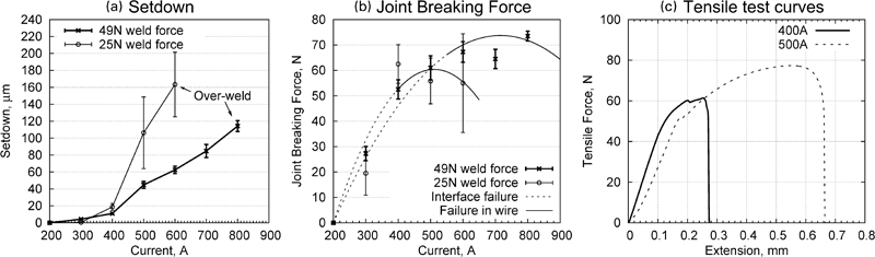
a measured setdown, b measured JBF and c load–displacement curves
The observed joint fracture modes are also indicated by line type in Fig. 2b. The transition from interface failure to failure in the wire occurred near 400 and 600 A for weld force settings of 25 and 49 N respectively. Failure through the wire indicates adequately strong bonds and the start of the process window, where interfacial failure indicates a brittle fracture mode with lower strength. This can be illustrated by examining representative force–displacement curves for an interface failure and failure through the wire using 25 N weld force at 400 and 500 A, as shown in Fig. 2c. The sudden decrease in tensile force (400 A) indicates a brittle fracture mode for the wire/block interface fracture. Similar to Khan et al., 4 the wire fracture shows a typical ductile fracture mode with decrease in tensile force before the actual failure occurs, indicating the initiation of localised deformation and thinning of the wire before failure. The same failure characteristics were observed for the tensile curves for 49 N weld force.
Weld microstructure
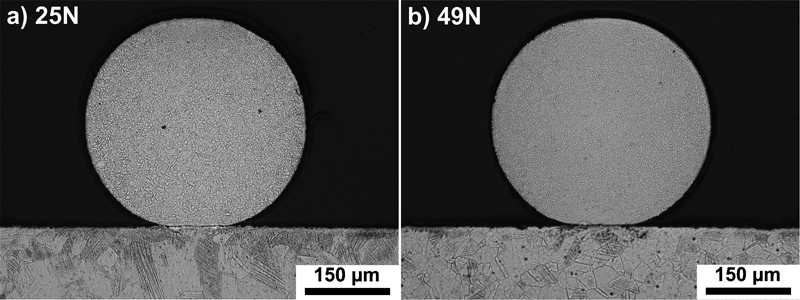
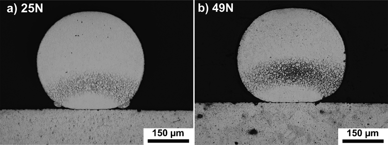
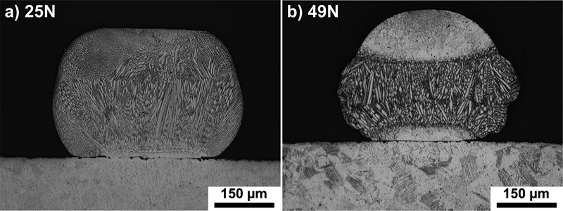
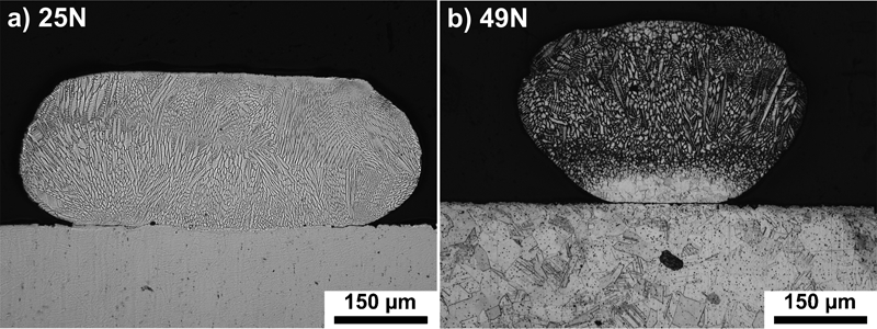
Cross-sections for welds made using currents ranging from 200 to 500 A for both 25 and 49 N weld force are shown in Figs. 3–6. At 200 A, the weld current was too low to register a bonding force (see Fig. 2b); however, the microstructure showed the onset of recrystallisation and grain growth primarily in the wire near the interface. For crossed wire welding, Fukumoto and Zhou2 showed an increase in interface contact area at low heat inputs and termed this to be ‘cold collapse’. Similarly, cold collapse of only the wire is observed in Fig. 3 due to the point contact as compared to the block. Furthermore, expulsion of locally melted material (also known as flash) at the interfacial microcontacts7 facilitates surface cleaning and bonding. Increasing the current to 300 A formed a zone at the lower part of the wire where preferential local heating seemed to occur, as shown in Fig. 4. Closer examination (Fig. 7a) revealed a partially molten region, which confirmed higher local peak temperatures. The interface and block microstructure showed no signs of melting or even being thermally affected by the process. The observed grain size and microstructure morphology of the block interface was identical to the bulk for the low current settings. The onset of significant melting of the wire for both 25 and 49 N weld force occurred when the welding currents reached 400 A (Fig. 5). Using 25 N weld force, almost the entire wire showed dendritic grains. A smaller melted volume was observed for the 49 N weld force, which was confined near the wire centre and bottom.
Weld cross-sections for 200 A
Weld cross-sections for 300 A
Weld cross-sections for 400 A
Weld cross-sections for 500 A
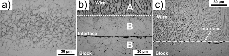
Close-up of a weld centre of 300 A, 25 N weld force, b interface of 400 A, 49 N weld force, solidified region (A), recrystallised region (B) and c interface of 500 A, 25 N weld force (right)
Detailed interface microstructure for welds created using 400 A, 49 N is shown in Fig. 7b. There was a transition from solidified region (A) at the centre of the wire to a relatively large grained recrystallised zone (B) on both sides of the wire/block interface. Since melting was not observed at the interface, the actual joint can be classified as a solid state bond. It should be noted that, before etching, there was no visible separation at the interface, indicating bond formation across the interface, while after etching, the interface was revealed (Fig. 7b). Similarly, Fukumoto and Zhou2 observed a clear interface (i.e. no visible bonded areas) for high strength bonds of Ni crossed wire welding, which was attributed to preferentially etching of the joint interface in solid state bonds.
Increasing the current to 500 A increased the heat generation and volume fraction of the molten material. The wire was severely deformed and completely melted with 25 N weld force, while at 49 N, the melting was restricted to the upper portion of the wire (Fig. 6). Figure 7c shows that the interface at 25 N force had been melted with a dendritic structure growing across the wire/block interface and producing a fusion bond. Increasing the weld force decreases the contact resistance and peak temperatures at the interface; hence, the upper portion of the wire became more susceptible to heating. For the high weld force setting, fusion bonding was found only to initiate at higher currents, as illustrated in Fig. 2b, showing the transition to fusion bonding where failure in wire started to occur.
At 500 A with both welding forces, the molten metal was observed to be in direct contact with the upper electrode, although no bonding or electrode sticking to the wire was observed during the experiments.
Heat generation, and consequently the weld mechanism, in resistance welding is highly influenced by the electrical and thermal contact resistances at the interfaces.7, 8 The observed weld mechanism is believed to be caused by interplay between the dynamic variation of interface contact resistance and the plastic deformation of the joint geometry during welding. The weld microstructure showed a clear difference in welding mechanism when increasing the force from 25 to 49 N. A higher weld force promoted intimate contact at the interface, which reduced the electric contact resistance and increased the thermal conduction. Furthermore, the higher force resulted in larger plastic deformations of the wire that significantly increased the initial contact area between wire and block. All these effects decreased the heat generation at the interface, which resulted in lower temperatures in the workpieces. This effect is prominent in the wire that has the smallest bulk material volume and heat capacity. Initiation of the molten region was found to originate at the wire centre due to the high heat flux away from the bond interface. At lower heat inputs, the measured joint strength was a result of solid state bonding. Increasing current and/or lowering the electrode force increased the heat development in the wire, thereby expanding the molten region in the wire. At sufficiently high heat inputs, the molten region could propagate into the interface, producing a fusion bond.
Hardness of weld zone
The measured hardness profiles across the weld zone for selected welding currents are shown in Fig. 8 for 25 and 49 N weld force respectively. In the block, the hardness values gradually decreased, approaching the interface, and reached a minimum of ∼200 HV. Near the top of the wire, the values increased for 300 and 400 A, while they remained low for 500 A.
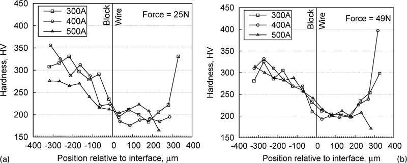
Hardness profiles for a 25 N force and b 49 N force
Cold working procedures are commonly implemented during the production of stainless steel components and result in a fine grained unidirectional structure with high hardness. The base metal wire hardness for the stainless steel used in this study was reported to be in the range of 480–500 HV.4 The thermal cycling experienced during welding induces softening due to the recrystallisation or resolidification of the material. The amount of softening can be related to the peak temperatures during welding,4, 9, 10 while the influence of cooling rate on post-weld hardness is negligible since martensite is not formed in austenitic stainless steels. The hardness profiles in Fig. 8 clearly show that the wire material experienced the highest degree of softening and hence the highest temperature during welding. This is supported by the cross-sections of the welds in Figs. 4–6, showing that melting and softening concentrated in the wire.
Comparing the observed microstructure of the welds at 400 A shown in Fig. 5 with the hardness profiles in Fig. 8, a good agreement was found. Increasing the electrode force from 25 to 49 N resulted in increased hardness in the top part of the wire, indicating that the temperature in the top part of the wire was lowered. The weld cross-section shown in Fig. 5 confirmed this, as the volume of the molten region was smaller and concentrated in the centre at a higher welding force. This is due to a decrease in electric contact resistance and increased conductive cooling through the electrode facilitated by the higher electrode force.
Mechanism of joint formation
The mechanism of joint formation in the cross-wire welding of Ni and Au plated Ni has been investigated by Fukumoto et al. 1, 2 and the cross-wire welding of SS316LVM by Khan et al. 4 For Ni wires, the primary bonding mechanism was found to be a strong solid state bond due to the creation of advantageous bonding conditions at the interface. Owing to the localised heating at the interface, the surface films and contaminants were melted and squeezed out during the initial stages of the bonding process, thereby promoting direct metal to metal contact, resulting in a strong solid state bond at the interface. The primary bonding mechanism in the cross-wire welding of SS316LVM wires was found to be fusion bonding initiating at the interface between the two wires. However, at low currents before fusion welding, solid state bonding was also observed.
In the present study, the evolution in bonding mechanisms is different from what was seen in microresistance spot welding and microresistance cross-wire welding. In Figs. 3–6, it is shown that the maximum temperatures were not concentrated around the bond interface in the case of wire to block welding. Rather, the observed bonding mechanism was based on the creation of a fusion zone first in the bulk of the wire. With increasing current, the fusion zone expanded into the entire cross-section of the wire and eventually penetrated through the block/wire interface. This promoted fusion bonding at the interface. At lower currents and before actual fusion bonding, the observed joint strength was the result of solid state bonding at lower currents (see Fig. 2). In order for solid state bonding to occur, at least limited interfacial melting is needed to clean the surfaces for bonding. In the case of wire to block welding, even though the highest temperatures are typically concentrated in the centre of the wire, the observed solid state bonding suggests that the interface still locally experiences transient temperatures high enough to at least partly melt and clean the faying surfaces for bonding.
The absence of fusion bonding at the wire/block interface may be attributed to the workpiece geometry, which induces a collapse of the wire onto the block. The proposed bonding mechanism observed in the current study is shown in Fig. 9. In the first stage (Fig. 9a), resistance heating increases the temperature in the bulk of the materials and interface due to the contact resistance created by the natural shape of the wire. In addition, the relatively small wire volume and contact with the upper electrode causes it to preferentially heat near the bottom.
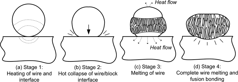
Schematic proposed RMW bonding mechanism for stainless steel 316LVM wire to block
In the second stage (Fig. 9b), the wire surface near the wire–block interface collapses. In contrast, due to the cooling of the electrodes, the top part of the wire is still strong enough to support the load and therefore remains undeformed. The collapse of the wire significantly increases the wire/block contact area, thereby distributing the stress and limiting the further collapse of the wire. This increased contact area also reduces the interface current density, which limits the local heat generation.
It is in the third stage (Fig. 9c) that melting initiates in the bulk of the wire due to heat build-up. Because the top electrode effectively conducts heat away from the wire, the electrode/wire interface does not reach peak temperatures sufficient for recrystallisation and softening. Hence, little plastic deformation occurs, and the electrode–wire contact area remains relatively unaffected. This was observed in the hardness measurements in Fig. 8.
At high enough heat inputs, the molten region will grow through the wire/block interface and produce a fusion bond (stage 4 in Fig. 9d). The further increase in current can result in weld defects due to excess heating, which can reduce the joint strength and create an irregular surface topography. In particular, for medical applications, smooth surfaces are desirable to avoid crevices that can cause issues with cleaning or corrosion resistance.
Khan et al. 4 tested the JBF for the cross-wire welding of 316LVM stainless steel wire of the same dimensions as in this study. The type of fracture and the maximum JBF agree well with the results in this work; however, the maximum JBF was found at lower currents than was necessary in the present study. This is credited to the observed difference in welding mechanism between cross-wire and wire to block microwelding.
The described mechanism of joint formation is mainly applicable to the microresistance welding of vacuum melted stainless steel 316LVM with the specimen dimensions applied in this work. It is indicated that the process is very dependent on the actual heat distribution due to the size and geometry of the workpieces. It is believed that the changing geometry and/or material type of the electrodes and workpieces can alter the mechanisms of joint formation in the microresistance welding of wire to block to others than the ones described here.
Conclusions
The present study examined the RMW of stainless steel 316L fine wire to a block of the same material. The JBF, weld zone hardness, fracture surfaces and weld development were investigated for 25 and 49 N weld force and with varying weld currents. From this, the mechanisms of fine wire to flat surface joint formation were detailed and compared to cross-wire joining. The main conclusions are summarised as follows.
The maximum JBF was just below 70 N for weld force settings of 25 and 49 N. The experimental variation in measured setdown and JBF (see Fig. 2a and b) was significantly higher for the 25 N weld force, and the most robust process was therefore obtained with the high weld force setting of 49 N. However, this setting required higher currents to produce a fusion bond having smooth surfaces and optimal JBF.
The observed dominating fracture mode for low heat input settings was brittle interface failure with total separation of the wire from the block. At higher heat inputs, failure transitioned to ductile fracture through the wire's softened heat affected zone.
The proposed bonding process includes initial heating of wire and wire/block interface; hot collapse of wire interface, increasing contact area; melting of the wire as well as local melting of the wire/block interface, producing solid state bonding; complete melting of wire and penetration of fusion zone across the bond interface, producing fusion bonding; and possible overheating and local thinning of the wire.
The paper details how the RMW of workpieces having significantly different geometries is possible although the bonding mechanism is ‘unusual’ compared to symmetric RMW. This has given greater insight into the bonding mechanism of such joints allowing expanding the application of the RMW process for the microjoining industry.
Footnotes
Acknowledgements
Billy Tan and Sui Kei Tang, University of Waterloo, Canada, are acknowledged for their great help with the experimental and metallurgical investigations. This work was supported by The Danish Council for Independent Research, Technology and Production Sciences, through the research project INNOJoint and by The Royal Danish Academy of Sciences and Letters as well as the National Science and Engineering Research Council (NSERC) of Canada and the Canada Research Chairs Program (![]() ).
).