
Abstract
Resistance microwelding of dissimilar materials such as Pt–10Ir and 316 low carbon vacuum melted stainless steel is becoming increasingly important for making electrical connections in medical devices. The joining of dissimilar materials increases flexibility in design while providing economic advantages, where more cost effective materials can be substituted for traditional materials. In this work, the performance of joints made using different electrode forces was studied by examining the surface morphology, cross-sections, joint break force and dynamic resistance measurements from resistance microwelding joints. Electrode sticking and excessive expulsion were observed with low electrode forces, whereas joints with undesirable cracks and notches were produced at higher electrode forces. Based on the analysis of single pulse welds, a new process variation using multiple pulses was developed, which improved the weld surface quality while obtaining a joint strength near 90% of the Pt–10Ir wire tensile strength.
Keywords
Introduction
Owing to excellent biocompatibility, mechanical properties and corrosion resistance, 316 low carbon vacuum melted (LVM) stainless steel (SS) is increasingly being used as lead wire in medical devices.1– 6 Traditionally, Pt alloys have been extensively used as electrodes in medical devices due to their excellent electrical conductivity, durability, biocompatibility and oxidation resistance. 1 5 1,5,7 However, Pt alloys are expensive, and making complete circuits from the material is not cost effective. Hence, there is an increasing demand in the fabrication of electronic and medical devices (i.e. pacemakers, cochlear implants, etc.) for electrical connections between components of dissimilar materials in order to reduce costs. 1 5 1,5,8
Crossed wire welding is a useful fabrication technique for manufacturing electronic components, such as implantable medical devices.1– 4,9 Alternative crossed wire joining processes include laser microwelding (LMW) and resistance microwelding (RMW). 1 8 1,8,10 Recently, the LMW process has been shown as a potential candidate for crossed wire welding of dissimilar materials. 7 11 7,11,12 However, many difficulties in the LMW of dissimilar materials were also found to exist. For example, the laser welds between dissimilar Pt and Ti alloys were shown to be susceptible to cracking due to the generation of brittle Ti3Pt phase,7 and porosity can also be a problem when laser welding dissimilar materials such as 316 LVM SS to Pt–Ir alloy.12 In addition, the laser welding process does not provide the self-fixturing advantage of the RMW process.1
RMW is widely used in medical industries since it is an economical process that offers excellent reliability and productivity at substantially lower capital costs. 1 2 4 1,2,4,13 There are some major differences in RMW compared to large scale resistance spot welding (LSRSW). Some of the differences of RMW include the following: substantially lower forces and currents, non-ferrous materials are often welded, electrode cooling is not possible and much faster cooling rates exist.1,14– 16 Many investigations into the bonding mechanism and dynamic resistance during the RMW of similar non-ferrous thin plates and fine wires have been performed.1,4,6,9,13– 18 Zhou et al. 14 and Ely and Zhou16 were the first to investigate the differences in RMW compared to LSRSW and outline the recommended process parameters to join thin Al, brass, Cu, Kovar, steel and Ni sheets. The bonding mechanisms have been shown to change with material properties and process parameters for similar material joints, including those of crossed wire geometry. Khan and Zhou2 have indicated the sensitivity of the crossed wire joining process to electrode force, where at low forces, the bonding mechanism is fusion welding, and at higher forces, solid state bonding occurs for 316 LVM SS alloy wires. Similar results were found by Friis et al. 6 during the RMW of 316 LVM SS wire to block. Fukumoto and Zhou showed that solid state welding occurs during the RMW of fine crossed nickel wires, and sound fusion welded joints could not be produced.13 The bonding mechanism becomes even more complicated when considering dissimilar material joints due to the difference in material properties (i.e. melting temperature, thermal and electrical conductivities, etc.), and there is limited literature on the RMW of dissimilar materials. Previous studies have shown that significant differences in bulk material resistance and melting temperatures have further impeded progress in the RMW of dissimilar materials, leading to the unbalanced heating of the system. 2 3 2,3,5 To the authors’ knowledge, no study thus far has developed an RMW process capable of overcoming these challenges in welding dissimilar crossed wires. Therefore, in this work, the surface morphology, cross-sections, joint break force (JBF) and dynamic resistance measurements from RMW joints were examined in order to fully understand the joint development between dissimilar 316 LVM SS and Pt alloy crossed wires. Using the knowledge obtained from this analysis, a new double pulse RMW process was developed for successfully welding dissimilar crossed wires.
Experimental
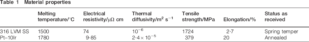
All the welds made in this study were made with a MacGregor DC400P direct current controller and a Unitek 80 A/115 V weld head equipped with flat RWMA class 2 (Cu–Cr) electrodes with a 3·2 mm face diameter. The dissimilar wire materials used in this study consisted of 0·38 mm diameter 316 LVM SS and Pt–Ir alloy. The chemical composition of the 316 LVM SS wire is Fe–0·024C–1·84Mn–0·75Si–17·47Cr–14·73Ni–2·76Mo–0·017P–0·001S–0·04Cu–0·024N (wt-%), and the Pt–Ir alloy wire had a composition of 90 wt-%Pt and 10 wt-%Ir. The material properties of each wire material are given in Table 1. Each wire coupon was ultrasonically cleaned in acetone before welding.
Material properties
A schematic of the crossed wire arrangement used during welding and the location of resistance measurements are shown in Fig. 1. The electrode displacement and the dynamic contact resistance at the faying interface were measured using a data acquisition (DAQ) system during welding. The resistance and displacement signals were measured at a sampling rate of 2·5×105 Hz.
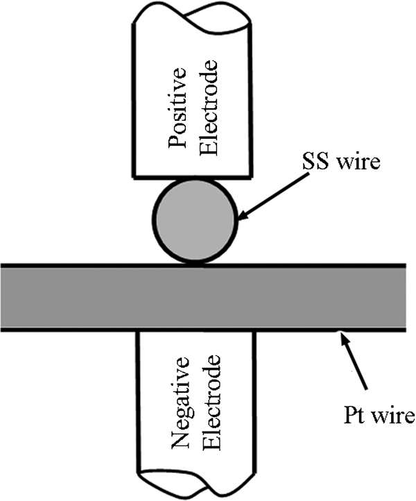
Schematic of crossed wire RMW process
Two different welding sequences were used, which included single and double pulse processes, as shown in Fig. 2a and b respectively. In single pulse welding, the electrode force was varied from 1 to 5 kgf. The current was varied between 100 and 500 A for a total weld time of 50 ms, including an upslope time of 10 ms and a downslope time of 3 ms. The single pulse weld sequence was similar to that used for the RMW of 316 LVM SS crossed wires in Ref. 4. The electrode force and current were varied because they have been found to have the largest effect on the evolution of the joint and, hence, the joint strength for the RMW of fine crossed wires.13 For double pulse welding, two pulses were applied with different electrode forces and current levels. The forces and currents were selected following observations made during conventional single pulse welding in order to optimise the JBF, weld appearance and geometry.
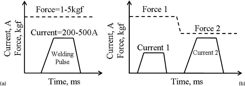
Schematic of welding sequence for a single pulse and b double pulse weld sequences
The weld surface condition, geometries and cross-sections were examined using a scanning electron microscope (SEM). Etching of cross-sectioned samples was not possible due to the galvanic reaction between the noble Pt–10Ir wire and the SS wire. Excessive pitting of the SS material occurred, rendering microstructural analysis impossible.
The JBF was measured for three or more welds at each set of parameters using an Instron model 5548 microtensile tester with a crosshead speed of 4 mm min−1. The joints were subject to a tensile shear loading condition, as illustrated in Fig. 3.
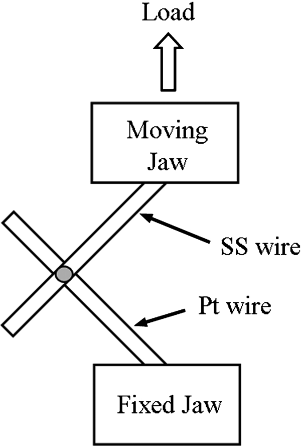
Schematic of tensile test set-up (not to scale): large arrows indicate direction of applied tensile force; joint is tested under tensile shear condition
Results
Joint geometry and cross-sectional morphology
Figure 4 Figure 5 Figures 4–6 illustrate the top and bottom surfaces of joints welded with electrode forces of 1, 3 and 5 kgf respectively. Excessive sticking and expulsion, resulting from overwelding, were observed in Figure 4 Figure 5 Figs. 4c, 5c and 6c when welding with currents of 200, 300 and 400 A and electrode forces of 1, 3 and 5 kgf respectively. Excessive expulsion and electrode sticking were deemed unacceptable under these weld conditions, and the weld surface condition was considered poor. It is well known that electrode sticking damages the electrode and reduces the electrode life. The electrode life is greatly depleted by sticking caused by local molten zones between the electrode and the workpiece during RMW. 14 14,19 Excessive expulsion or poor surface quality is also not acceptable in electronics or medical device applications due to joint reliability and the possibility of electrical shorts, contamination or even damage to living tissue.
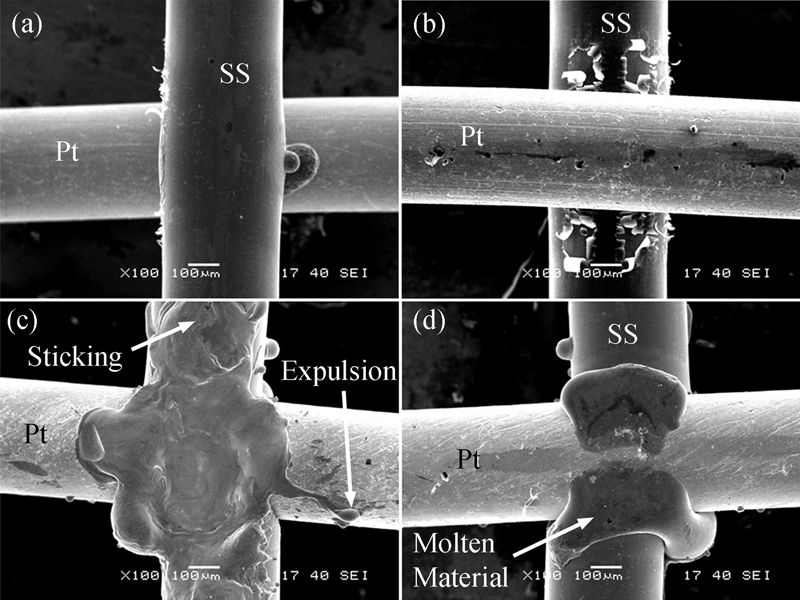
a top and b bottom of weld made with 1 kgf electrode force and 150 A welding current and c top and d bottom of weld made with 1 kgf electrode force and 200 A welding current
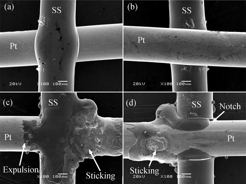
a top and b bottom of weld made with 3 kgf electrode force and 200 A welding current and c top and d bottom of weld made with 3 kgf electrode force and 300 A welding current
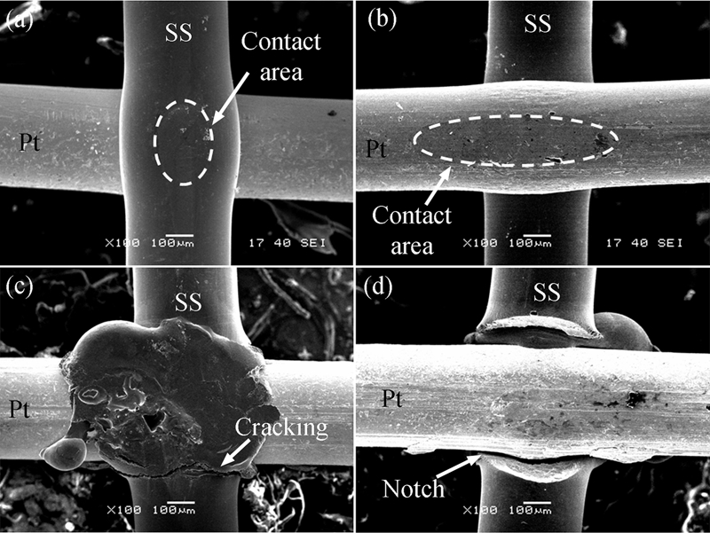
a top and b bottom of weld made with 5 kgf electrode force and 200 A welding current and c top and d bottom of weld made with 5 kgf electrode force and 400 A welding current
From Figure 4 Figure 5 Figs. 4–6, it was found that the process window for welding current, where an acceptable joint morphology was observed, increased from 50 to 200 A when the electrode forces increased from 1 to 5 kgf. As expected, a higher electrode force broadens the process window of possible welding currents, where expulsion and electrode sticking were not an issue. An increased contact area between the electrode and the wires as well as at the faying surface between the wires results from the deformation of the wires under higher electrode forces. This results in a decrease in electrical resistance and joule heating at the interface between the electrode and the wire and at the faying interface. Flattened areas were clearly seen on the welds made with 5 kgf and 200 A in Fig. 6, where a considerable amount of deformation had taken place. It is well known in the welding community that higher electrode forces will reduce the contact resistance and Joule heating in a resistance welding process due to microscopic deformation of asperities.20 However, in crossed wire welding, the changes in the contact area are also due to macroscale deformation, which has an even larger effect on the resistance at the electrode wire and faying interfaces.13 The contact area in crossed wire welding is extremely dynamic. Although higher electrode forces helped prevent expulsion and electrode sticking, defects such as cracks, notches and unwanted extruded material were found due to the heavy deformation of the SS wire, as shown in Figure 5 Figs.5d and 6c and d. Figure 7 shows the low and high magnification SEM images of joint cross-sections welded with an electrode force of 5 kgf and currents of 300 and 400 A respectively. At low current, a notch was observed right below the diameter of the Pt wire, shown by dashed lines in Fig. 7b. At high current, the edge of this notch was tangent to the surface of the Pt/Ir wire, as shown in Fig. 7c, indicating that the crossed wire weld geometry had caused the formation of this notch.
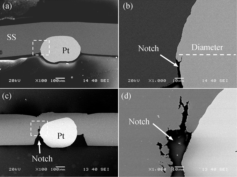
Low and high magnification SEM cross-sectional images of joints welded with electrode force of 5 kgf and current of a, b 300 A and c, d 400 A, showing formation of notch
Joint breaking force
Figure 8 shows the JBF as a function of current and the corresponding fracture modes for the welds produced with low, medium and high electrode force parameters of 1, 3 and 5 kgf respectively. It was found that the electrode force had a large effect on the maximum achievable JBF and the size of the process window with respect to welding currents. The largest JBFs were realised with the lowest electrode force of 1 kgf, where the joint fractured in the Pt–Ir wire, as shown in Fig. 9a. At 200 A, the average JBF was measured to be 38·8 N, which is 90% of the 43 N (i.e. 379 MPa) tensile strength of the Pt–Ir wire. The weld strength, however, was found to decrease with increasing electrode force. The maximum JBF measured at the highest electrode load of 5 kgf was 27·3 N with a welding current of 500 A. Fractures of the welds made with 5 kgf were either interfacial or originated from a notch defect in the SS wire, as shown in Fig. 9b and c. The notch defect in combination with insufficient melting is expected to have caused the lowered JBF for welds made with higher electrode forces of 3 and 5 kgf.
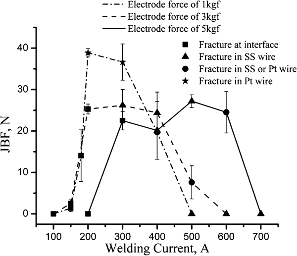
Joint breaking force versus welding current for joints made using electrode forces of 1, 3 and 5 kgf: error bars show one standard deviation
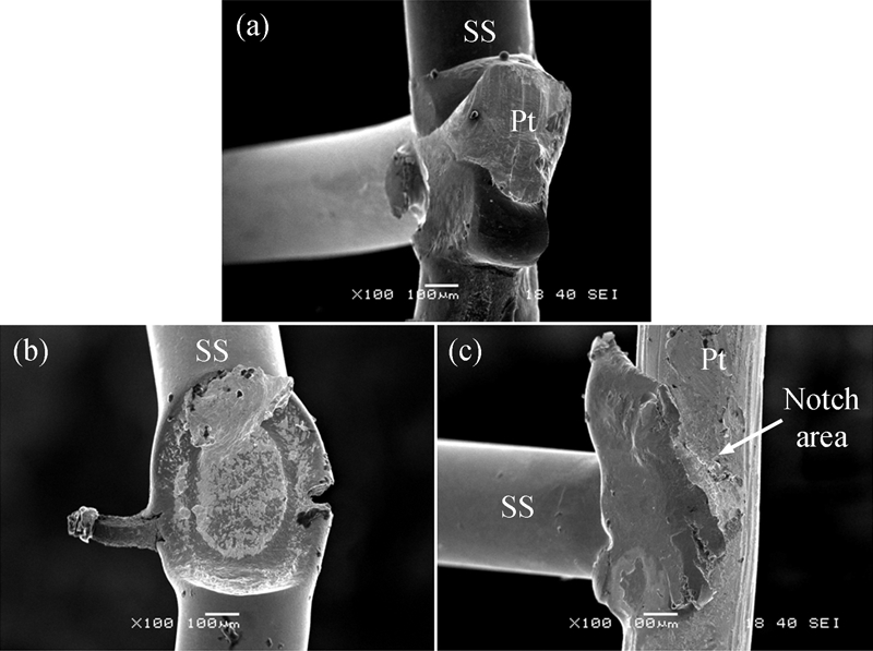
Fractured surfaces of joints made with a 200 A, 1 kgf, b 300 A, 5 kgf and c 400 A, 5 kgf
Electrode displacement and dynamic resistance measurements
Dynamic resistance measurements have been found to be very useful in studying the nugget formation for both LSRSW21 and RMW processes. 20 20,22 In the conventional sheet to sheet resistance welding of similar materials, different stages of the welding process have been identified. In the first stage, the resistance drops due to surface breakdown, asperity softening (i.e. reduction in contact resistance) and surface melting followed by an increase in resistance in the second stage, where the bulk resistance increases due to increased bulk temperature and weld nugget growth. In the final stage of the resistance welding process, either mechanical collapse of the joint or loss of material due to expulsion causes shortening of the current path, causing a second reduction in bulk resistance.20– 22
The conventional stages of sheet to sheet resistance welding mentioned above were found to be similar for this dissimilar crossed wire RMW process. Typical electrode displacement and dynamic wire to wire resistance measurements for welds made with a current of 200 A and electrode forces of 1 and 5 kgf are provided in Fig. 10. The peak resistance of the 1 kgf weld was substantially higher than that of the weld made with 5 kgf with resistances of 0·0084 and 0·0065 mΩ respectively. This was caused by the large difference in contact resistance resulting from differences in contact area at the faying interface when varying the electrode force. The lower contact resistance of the 5 kgf weld explains the extremely low JBF (Fig. 8) caused by insufficient melting. The displacement measured for the 5 kgf weld, shown in Fig. 10, shows set-down by deformation only. On the other hand, a large amount of melting took place for the 1 kgf weld with a welding current of 200 A, and the electrode displacement or set down observed in Fig. 10 was substantially larger than that of the 5 kgf weld. In addition, a peak in the dynamic resistance data (i.e. the ‘melting peak’) was observed similar to that observed in the RMW of thin Ni sheets.20 This melting peak was not observed for the 5 kgf weld, where no melting was observed. The large amount of displacement or set-down for the 1 kgf weld was therefore caused by deformation at elevated temperatures and melting of the SS wire, as shown in Fig. 4d.
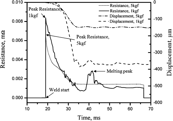
Electrode displacement and dynamic resistance measured during welding with electrode forces of 1 and 5 kgf and 200 A welding current
Discussion
Resistance welding of dissimilar materials
The well known problem of joining dissimilar materials using resistance welding2 has proven to complicate the joining of 316 LVM SS and Pt–10Ir crossed wires. The desired localisation of melting only at the faying interface was not possible. It was easily seen that the differences in material melting temperature and electrical resistivity (Table 1) play a large role in joint quality. The material properties for both 316 LVM SS and Pt–10Ir are provided in Table 1. The large difference in material properties explains why balancing the electrode force and current to achieve sufficient local heat generation to get surface melting and facilitate plastic deformation and set-down of the SS wire, as described in Refs. 1, 13 and 14, was not possible in this study. As the welding current is increased, the SS wire material with lower melting temperature and higher electrical resistivity melts and wets the unmolten Pt–Ir wire, as shown in Figure 4 Figs. 4d and 5d. Although melting at the faying interface of the two wire materials can be desirable, melting of the SS wire at the electrode interface leads to electrode sticking and expulsion, as observed with either low electrode force or high welding currents in Figure 4 Figure 5 Figs. 4c, 5c and 6c. In addition, inevitable softening of the SS wire and the round wire geometries was found to lead to the formation of a notch as seen on both the weld surfaces ( Figure 5 Figs. 5c and 6c) and cross-sections (Fig. 7). The softened SS wire is essentially cut by the Pt–Ir wire due to the force applied by the electrodes. Only with relatively high heat input can the molten SS heal the notch, as shown in Figure 4 Figs. 4d and 5d. However, expulsion and electrode sticking also occur with a large heat input.
From the analysis of the previous results, it was realised that in order to achieve optimum JBF values with acceptable surface quality and reduced electrode sticking, a novel technique must be developed. The traditional methods of balancing the electrode force and welding current are insufficient in this dissimilar crossed wire application. In LSRSW, several different techniques have been utilised to localise or balance the heating so that melting only occurs at the faying surface when joining dissimilar materials or sheets of different thickness. Some of these techniques include using two electrodes with different geometries, water cooling one electrode, 23 23,24 using electrodes with different resistances or surface coatings23 or modifying the welding schedule, for example using multiple pulses. 25 25,26 However, in the crossed wire RMW process, using wires of different geometries or electrode cooling is not feasible,1 and the substantial difference in material properties cannot be compensated for by simply changing the resistance of the electrodes. It was therefore decided to utilise the knowledge gained in the analysis from the previous sections to develop a suitable double pulse process.
Development of double pulse welding procedure
From the analysis of the JBF, joint morphology and dynamic resistance measurements, it was observed that at low forces, the SS wire becomes almost completely molten, which provides excellent JBF but causes electrode sticking and poor surface quality. At higher electrode forces, the JBF was sacrificed due to the formation of defects, such as cracks and notches, which were not healed due to insufficient melting. Therefore, an ideal welding schedule would include a high electrode force at the beginning of the weld sequence to reduce the contact resistance at the electrode wire interface. In the second pulse, a lower force should be used to produce sufficient heat generation and cause melting of the SS wire at the faying surface only, increasing the joint strength while avoiding excessive expulsion and electrode sticking.
In the double pulse schedule developed in this study, the first step of the welding process was designed to deform the wires, producing a larger contact area between the wire and the electrodes in order to increase the current threshold for expulsion and electrode sticking. An electrode force of 5 kgf and a welding current of 200 A were chosen for the first pulse because, as observed in Fig. 6a and b, deformation at the electrode wire interface occurs without unwanted weld defects, such as cracks or notches. In addition, as observed in the dynamic resistance measurements (Fig. 10), the displacement or set down was caused only by deformation (Fig. 9b) using these parameters.
A 100 ms delay was inserted before the second pulse in order to allow for the electrode force to stabilise before the second current pulse was applied. In addition, the system is allowed to cool down to approximately room temperature according to the theoretical cooling rate of 104–105 K s−1 in RMW.1 Therefore, adding in the delay simplifies the process by reducing the amount of unknowns, namely, the initial load and temperature for the second pulse. A planned future study will investigate the effects of the time delay.
For the second pulse, the welding current was initially maintained at 200 A, and the electrode force was varied from 1 to 5 kgf. After taking JBF measurements, it was realised that only at the lowest force of 1 kgf (i.e. lower machine limit), sufficient heating and joint strength were achieved, as shown in Fig. 11a. The welding force of 1 kgf was therefore selected for the second pulse. Next, the second pulse current was optimised for JBF and surface quality. As shown in Fig. 11b, the maximum JBF of 37·4 N was obtained with a second pulse welding current of 300 A. Full set down of the SS wire and excellent joint surface quality were achieved at welding currents of 250 and 300 A, as shown in Fig. 12. Only mild electrode sticking was noticed on the Pt–Ir wire for welding currents of 300 A, as shown in Fig. 12c and d. Lowering the current slightly was found to solve this problem, as shown in Fig. 12a and b, where no electrode sticking was found with a welding current of 250 A.
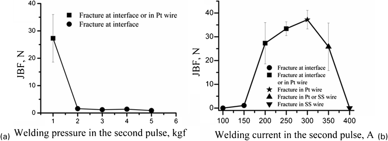
a JBF versus second pulse electrode force (second pulse current of 200 A) and b JBF versus second pulse welding current (electrode force of 1 kgf): error bars show one standard deviation
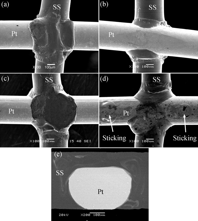
a, c top and b, d bottom views of joints made with double pulse welding process with second pulse with electrode force of 1 kgf and with welding current of a, b 250 A and c, d 300 A and e cross-sectional image of weld in c
Figure 13 shows the dynamic resistance and electrode displacement measurements during double pulse welding with electrode forces of 5 and 1 kgf and welding currents of 200 and 250 A for the first and second pulses respectively. It was observed that only cold collapse and hot collapse deformation take place in the first pulse, while melting occurs during the second pulse, as indicated by the melting peak in the resistance measurement. The initial resistance in the second pulse is lower than that of the first. This is a result of an increased contact area after the first pulse and a decrease in bulk resistance of the wire materials due to cooling during the 100 ms delay. It was also observed that almost complete set down of the SS wire was measured with a total displacement of 0·34 mm after welding. This double pulse RMW process was therefore found to successfully join dissimilar 316 LVM SS and Pt–10Ir wire materials, providing excellent joint strength, weld geometry and surface quality.
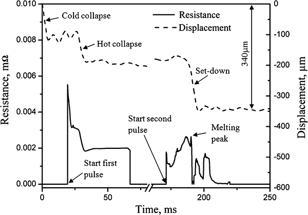
Displacement and dynamic resistance measurements made during welding with optimised double pulse parameters
Conclusions
The RMWs of dissimilar 316 LVM SS and Pt–10%Ir wires have been investigated by analysing weld surface morphology, cross-sections, JBF as well as dynamic resistance measurements. Following the analysis of single pulse welds, double pulse welding was proposed to produce a sound joint with acceptable joint geometry and surface quality. The major conclusions of this work are summarised as follows:
The electrode force was found to be a key factor in the RMW of dissimilar wires. Welding in low electrode force results in excellent JBF; however, electrode sticking and poor surface quality were observed. With increasing electrode force, the JBF was sacrificed due to weld defects, such as cracks and notches, but electrode sticking and expulsion were not issues.
A notch resulting from the crossed wire joint geometry and unbalanced heating in the RMW of dissimilar material was found when insufficient melting occurs. This notch can be healed by the reflow of molten materials, improving the joint performance.
A sound joint with a JBF of 37·4 N, 87% of the tensile strength of Pt–10Ir wire and an acceptable surface quality was achieved using multiple pulse welding.
Footnotes
Acknowledgements
This work has been partially funded by the Natural Science and Engineering Research Council of Canada (http://www.nserc-crsng.gc.ca) and the Program of Canada Research Chairs (CRC) in Microjoining (![]() ). The help of Professor W. H. S. Lawson in reviewing this manuscript is greatly appreciated.
). The help of Professor W. H. S. Lawson in reviewing this manuscript is greatly appreciated.