
Abstract
The fracture mode of spot welded joints, made of SAPH440 steel sheets, is investigated. It was found that the weldment failure in the peel test of the joints occurred through the weld nugget. This is called an interfacial failure and is not acceptable because it is a sign of insufficient mechanical strength. Investigation showed that this kind of fracture is attributed to the brittleness of the nugget zone, caused by its martensitic microstructure due to the high cooling rate in the welding. For eliminating this defect, resistance spot welding procedures were augmented with post-heating stage. This approach is intended to reduce the cooling rate after welding and also to temper the weld nugget, generating a more ductile microstructure in the weld zone. The results of this research can be used for planning spot welding process and provides a guideline for analysing the results of hardness and peel test.
Introduction
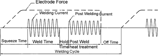
Resistance spot welding (RSW) remains the primary process for joining body sheet metal in the automotive industry. The embedded infrastructure coupled with its superior surface finish makes RSW an economical process and aesthetically very desirable as well. During the RSW process, two continuously cooled electrodes clamp down on two or more worksheets; alternating or direct current is then passed through the electrodes at low voltage, which results in fusion at the faying surfaces of the worksheets. Each welding schedule typically involves four sequential steps:1
squeeze time
weld time
hold time
off time.
The latter is generally applied where the welding cycle is repetitive.
High strength steels (HSS) have gained popularity due to their inherent strength and ductility characteristics. A JIS G3113 SAPH440 steel is used in the Asian automobile industries for body structures due to its formability and strength. A common concern about SAPH440 is its weldability problem, where interfacial fractures of its welds are reported under peel testing. Similar problems have been observed in HSS and advanced HSS.
Spot weld failure mode is a qualitative measure of the weld quality which is of two types: interfacial and pullout. When the failure occurs through the weld nugget, it is called an interfacial failure, while in pullout mode, failure occurs by complete (or partial) withdrawal of the nugget from one sheet. Load carrying capacity and energy absorption capability for those welds that fail under interfacial mode is low compared to the pullout mode; 2 2,3 this is why the pullout mode is more desired.
Gould et al. 4 4,5 tried to find the reasons for hold time sensitivity (HTS) of HSS. They concluded that HTS was only observed in the transformation hardened steel through a combination of disadvantageous stress states (undersized welds) and a crack susceptible microstructure.
Khan et al. 6 studied the effect of weld microstructures on static and impact properties of advanced HSS spot welded steels. They stated that interfacial failure occurred when testing dual phase 600 (DP600), transformation induced plasticity 780 (TRIP780) and high strength low alloy steels. In addition, the weld test results by Sun et al. 7 show that, under lap shear loading, the weld fusion zone size is a critical factor in its static performance in terms of failure mode, peak load and energy absorption of DP800 and TRIP800 spot welds. The work of Yang et al. 8 showed that the weld length, specimen width and sheet thickness had great effect on the failure modes of the tensile testing specimen at DP600 steels.
Recently, Pouranvari and Marashi9 stated that there is no direct relationship between the tendency for interfacial failure and ultimate tensile strengths of base metals of DP and TRIP steels. Chuko and Gould10 and Marya and Gayden11 studied the idea of in situ post-weld heat treatment on TRIP and DP steels. It has been shown that tempering is an effective way of reducing HTS in hardenable HSS. Gould et al. 12 also predicted underlying joint microstructures for a range of processing approaches, steel types and gauges. It has been shown that the cooling rate at the RSW cycle is much higher than other welding processes.
Khan et al. 13 used the second pulse current to alter the cooling rate of RSW also to control the hardness of the fusion zone and heat affected zone (HAZ).
The main objectives of this study are to investigate the failure mode of SAPH440 steel and to avoid undesirable modes of failure in destructive testing.
Experimental procedure
In order to study the effect of welding current and welding time on the failure mode and to obtain the practical welding parameters, a set of experiments are carried out. These experiments are required to achieve appropriate weld nugget sizes. At first, the weldability lobe diagram referring to SAPH440 sheet is obtained by adjusting the welding current and welding time.
Hold time sensitivity test
In order to study the effect of different holding times on the failure mode, two series of peel test samples are prepared, one with low holding time and the other with high holding time.
Post-heating
An experiment is run to study the effects of post-heating parameters on the weld. The approach is the application of the post-heating stage to achieve good quality of residual metallurgical phases and to minimise the weld interfacial failure of SAPH sheets. As shown in Fig. 1, the post-heating stage can be considered as a heat treatment process except that the heat source is local, which is applied to the weld sample after holding time.
Stages of double pulse scheme of welding
The stages of double pulse scheme of welding are as follows:
welding current and time selection: welding current and time are chosen to be 12 kA and 13 cycles respectively
hold time selection: hold time is then selected to be 70 cycles initially; after determining the post-welding current and time, this parameter is decreased to a suitable value
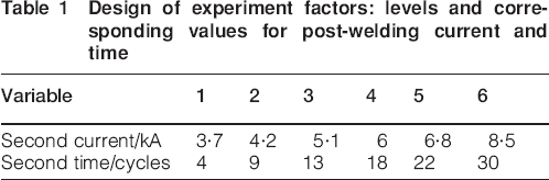
welding trials: welds are then made over a range of post-welding currents and times based on design of experiments method with six levels for each factor (Table 1); two samples for peel testing and one sample for shear–tensile testing are made at each run, leading to 108 samples
hardness tests: one surface of each sample is polished for hardness testing; on each sample, a single Rockwell C (HRC) hardness test is performed at the centre of the exterior weld surface
peel test trials: in order to record the failure modes, peel testing is performed so that the hardness results and peel test results can be compared
metallographic examinations: metallographic sections are taken from two samples, one with no applied post-heating and the other with effective post-heating (7 kA and 22 cycles); these samples are then sectioned and examined using 2% nital etchant and standard metallographic procedures
shear–tensile tests: shear–tensile tests are then performed on samples in order to study the effect of the post-heating stage on the mechanical properties of welds.
Design of experiment factors: levels and corresponding values for post-welding current and time
Experimental set-up
Materials and equipment
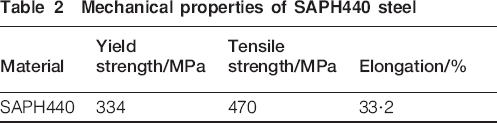
The type of material used is a JIS SAPH440, 2 mm thick, with a chemical composition of 0·15C–1·02Mn–0·17Si–0·012P–0·011S–0·004Cr–0·02Ni–0·009Mo–0·037Al–0·002Co–0·003V–0·001Ti–0·03Cu (wt-%), and its mechanical properties are shown in Table 2.
Mechanical properties of SAPH440 steel
Actual welding trials are performed using a 100 kVA press type spot welder, equipped with a constant current controller. Domed tip electrodes with 8 mm face diameters are used, and the electrode force is kept constant for all welding trials at 5·5 kN. The accuracy of the time, current and force are verified by a TECNA Weld Tester TE1600 so that the welding parameters can be precisely regulated.
Destructive testing
Since failure mode is a qualitative measure of weld quality, the morphology of fracture is examined using peel testing and shear–tensile testing. This is performed to see if there is a weld button pullout or an interfacial fracture and to determine the size of the weld button. In the peel test (Fig. 2), a manual peel test provides the qualitative information of the weld.14
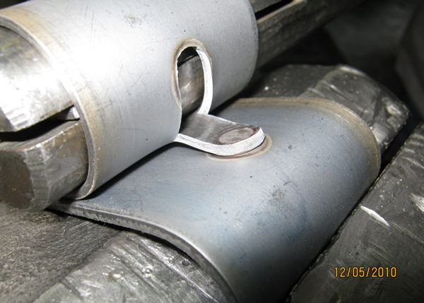
Peel (roller) test
Two sheets are pulled apart along the uniaxial direction until the fracture takes place. However, in the tensile peel test, the specimen is bent along a certain distance while one sheet is fixed in the machine and the other sheet is pulled in the opposite direction, and a fracture is observed. In this study, dimensions of peel testing and shear–tensile testing coupons were 140×50 mm and 138×60 mm respectively, according to ANSI/AWS/SAE D8·9-97.
A SANTAM STM-150 testing machine is used for shear–tensile testing with a constant crosshead velocity of 10 mm min–1. The force–displacement curve is recorded during each test, and the shear–tensile strength and the peak load in the load displacement curve are extracted. The failure mode of each specimen is also recorded during experiments.
Results and discussion
Generally, two types of failure modes are observed during the peel test of the SAPH sheet spot welded joints: interfacial and pullout mode, as shown in Fig. 3.
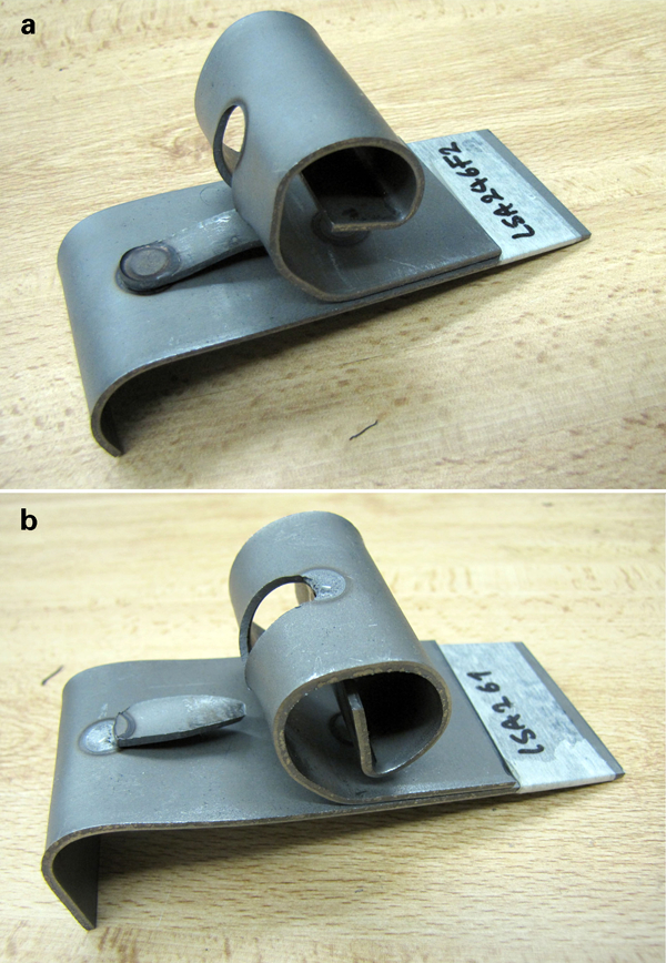
a button pullout fracture and b interfacial fracture
Hold time sensitivity
Two series of weld samples are prepared to observe hold time effects on the failure mode (Table 3). One important reason for repeating this test number is to examine the test–retest reliability of the weld machine. It is observed that all samples shown in Table 3 include fracture initiating along the interface, including full or partial. Thus, decreasing the hold time cannot be recognised as a good way to reduce interfacial fractures in a SAPH440 spot weld joint, due to the high cooling rate of the weld button, which is ∼5000°C s–1,11 at which the possibility of a brittle structure is high.
Welding parameters
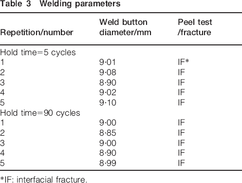
*IF: interfacial fracture.
Effect of post-heating current and time on hardness of nugget and failure mode
Figure 4 shows the measured HRC of SAPH welds at different post-welding times and post-welding currents. While the currents and times of the post-heating stage are low, there is not enough energy to temper the weld effectively; thus, the hardness of the weld is still high at first and second levels of post-welding times and currents. It is noted that the hardness of the nugget generally decreases with increasing post-welding time and post-heating current. After a specific range, however, it increases due to excessive heat input of the second pulse, which again makes the weld brittle and hard. It can be seen that the effect of time is more stable than the effect of the current on weld hardness, that is, the area of lowered hardness is more extended along the time than the current. Similar behaviour is observed while considering the peel test results in Fig. 4. Typical interfacial and pullout fractures are also shown in Fig. 4b and c. Since the hardness of nuggets is decreased by utilising the post-heating stage, approximately all samples exposed to the post-heating stage have failed in a pullout failure mode. Those samples that are exposed to an insufficient post-heating stage are exception because they have a fracture among the interfacial surface, which is due to an inadequate heat input for performing a proper heat treatment process. Figure 4 also proves that due to excessive heat input in the combination of post-heating current and time at the sixth level, an interfacial fracture is induced. It is also implied that short post-welding time combined with even high post-welding currents does not alter the fracture mode from interfacial to pullout.
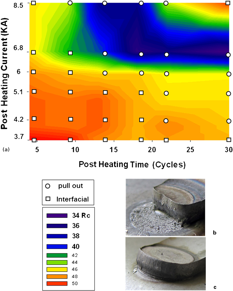
a hardness of nugget and failure mode at different post-welding current and time, b typical interfacial fracture and c typical pullout fracture
Microstructure study of post-heating stage
The microstructure of the weld nugget is observed to be quite different from the base metal and is affected by the heat input in the heating stage and post-heating stage. Two microstructural studies, one without a post-heating stage and another with post-heating, are performed forgetting a better insight of the effects of the post-heating stage on the hardness of weld.
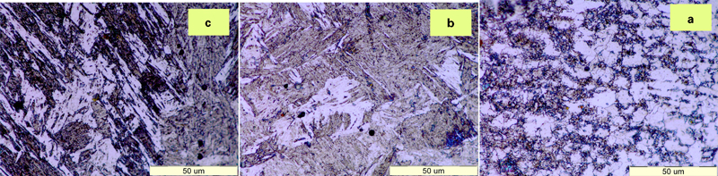
Figure 5 shows a typical microstructure of SAPH steel resistance spot welded joint. The joint region consists of four distinct structural zones: base metal, intercritical HAZ, coarse grain HAZ and the fusion zone. As shown in Fig. 5a, the microstructure of base metal consists of ferrite grains with a small amount of Fe3C. The fusion zone contains a directional columnar structure growing towards the centreline. A needle-like martensitic structure within the fusion zone is shown in Fig. 5e. Despite the low carbon content of the base metal, the martensite phase is formed due to the high cooling rate involved in RSW process. The presence of water cooled copper electrodes and their quenching effect, as well as the short welding cycle, can explain the high cooling rate of RSW process. The HAZ structure is shown in Fig. 5b containing intercritical HAZ (right) and coarse grain HAZ (left). At a closer view, Fig. 5c shows that the intercritical HAZ consists of finely dispersed martensite particles and carbides within the ferrite matrix. The fine structure in the fine grain HAZ results from peak temperatures slightly surpassing Ac3, which promotes austenite nucleation, while rapid cooling limits grain growth, forming the fine grained structure.
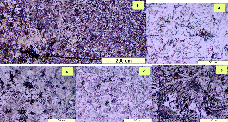
Microstructure of a base metal, b HAZ, c intercritical HAZ, d coarse grain HAZ and e fusion zone
Figure 6 shows a typical hardness profile of the SAPH steel weld, which exhibits a significant hardness increase from the base metal. The hardness of the weld nugget is about three times more than that of the base metal, at a value of ∼420 HV. Higher hardness of the weld nugget can be attributed to the martensite formation in this zone.
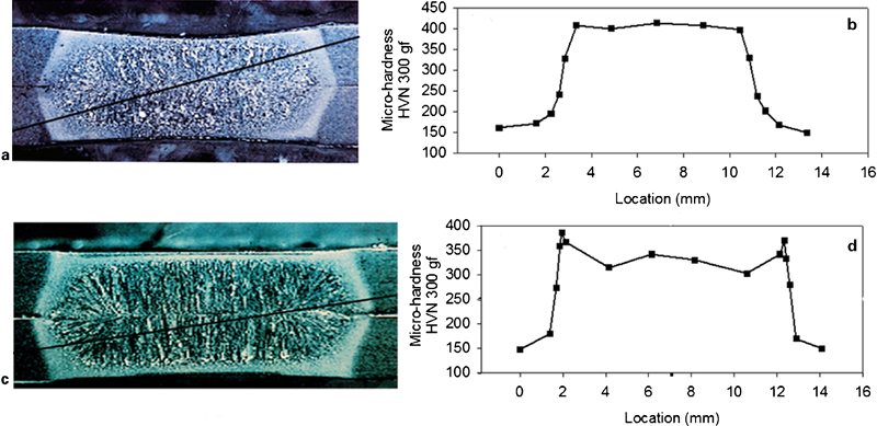
Typical microhardness profile of SAPH steel along diagonal line after spot welding with welding current of 12 kA, welding time of 13 cycles and holding time of 5 cycles
Figure 7 shows a typical microstructure of weld where the welding is performed under welding current of 12 kA, welding time of 13 cycles, holding time of 70 cycles, post-welding current of 7 kA and post-heating time of 22 cycles. As shown in Fig. 7c, the post-heating parameters have a significant effect on the microstructure of the nugget region. It is observed from Fig. 7c that the ferrite phase in the fusion zone is transformed to a more ductile ferrite form. Generally, the post-welding stage is intended to permit some transformation of the austenite before the martensite's start temperature to reduce the proportion of martensite in the weld.
Microstructure of a intercritical HAZ, b coarse grain HAZ and c fusion zone
As illustrated in Fig. 6c and d, the hardness of the nugget is reduced considerably due to the post-heating stage. By exerting the post-heating stage, the hardness of the weld nugget becomes about two times more than that of the base metal, at a value of approximately 300 HV.
Tensile–shear testing of SAPH steel
As shown in Fig. 8, it is observed that the force–displacement curve presents a nonlinear region before reaching the peak load in the shear strength test. It was expected that the load would drop to the zero point after propagating the crack along the circumference of the nugget. However, since the button pullout fracture occurs in the test, the load does not reach the zero point until completing the nugget pullout fracture by tearing of base metal along the loading direction.
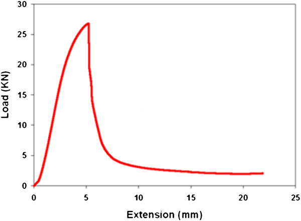
Typical load–displacement curve of a SAPH sheet spot welded joint
It is observed that there is not a noticeable difference between peak loads at various post-heating states as compared to Fig. 9. Another noticeable outcome of these tests is that all samples failed at pullout mode even those that failed at interfacial fracture in the peel test. It seems that the low speed of the testing machine and alignment of the nugget with the loading line is causing such a phenomenon.
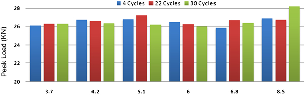
Tensile shear strength versus post-heating current and time
Verifying developed process in production line
The reliability of the current procedure for RSW of SAPH steel sheets is assessed by testing it on two parts of an auto body as a case study. Figure 10a and b shows two parts of an auto body that are assemblies of SAPH steel sheets with a thickness of 2 mm. The method developed in this article was verified at the production line so that 50 samples are welded using a post-weld heating stage and some are destructed randomly. As can be seen in Fig. 10c and d, failure tends to occur under the interfacial mode once samples are not exposed to the post-heating stage. For post-heating time at 18 cycles and post-heating current at 6 kA (Fig. 10d), however, the weld peels with full button morphology. The results for the second part are the same. Therefore, the presented methodology in this research is proven to be an effective method to reduce interfacial fractures in the peel testing of SAPH weldments.
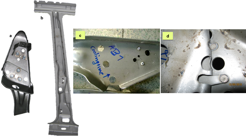
a, b one sub-assembly and one part of chassis used for case study and two destructed samples c without post-heating stage application and d using post-heating stage (squeeze time, 15 cycles; weld time, 13 cycles; weld current, 12 kA; hold time, 40 cycles; post-heating current, 6 kA; post-heating time, 18 cycles)
Conclusions
A spot weld is considered acceptable when the peel test reveals a pullout shape. However, spot welded joints of SAPH440 steel sheets exhibited a higher tendency to fracture interracially rather than pullout mode. Referring to this defect, the effects of post-heating time and post-heating current on weld quality of SAPH440 steel sheets were experimentally investigated in this work. A sufficient number of weld samples were prepared and examined. From this study, the following conclusions can be drawn.
The capability of applying post-heating current as a heat treatment process for eliminating interfacial fractures is shown. In addition, peel tests have demonstrated that post-heating time reduces interfacial fractures but with lower rate.
Increasing post-heating current and time beyond optimum values, in contrast, causes the nugget to go through a quench stage from high temperatures and therefore increases the chance of interfacial failure.
Since a martensitic weld area is often a precursor to reduced mechanical performance, the post-welding stage is intended to permit some transformations of the austenite before the martensite start temperature and to reduce the proportion of martensite in the weld.
The post-heating stage does not have a significant effect on the shear–tensile strength of SAPH spot welded joints and the failure mode at this mechanical test.
The procedure used in the current study is recently being adopted for welding SAPH440 sheets in a car body assembly line.
Footnotes
Acknowledgements
The authors express their gratitude towards Mr Roohnavaz from Haddad Partov Co. for the invaluable technical support provided for this work.