
Abstract
ZrB2–SiC ceramic composite was brazed by using TiZrNiCu active filler metal. The microstructure and interfacial phenomena of the joints were analysed by means of SEM, energy dispersive X-ray spectroscopy and X-ray diffraction. The joining effect was evaluated by shear strength. The results showed that the reaction products of the ZrB2–SiC ceramic composite joint were TiC, ZrC, Ti5Si3, Zr2Si, Zr(s,s) and (Ti, Zr)2 (Ni, Cu), and the microstructure was separately ZrB2–SiC/Zr(s,s)/Ti5Si3+Zr2Si+TiC+ZrC+(Ti,Zr)2(Ni,Cu)/Zr(s,s)/ZrB2–SiC. A conceptual interface evolution model was established to explain the interface evolution mechanism. The maximum shear strength of the brazed joints was 143·5 MPa at the brazing temperature T of 920°C and the holding time t of 10 min.
Introduction
Zirconium diboride (ZrB2) has been considered as one of the ultrahigh temperature ceramics (UHTCs), which with appropriate compositions are attractive for high temperature structural applications. ZrB2 based UHTCs are promising materials in extreme environments such as reentry vehicles, hypersonic cruise aircraft and hypersonic flight of ballistic missiles because of their unique combination of high melting point (>2700°C), high strength and hardness, good thermal shock resistance and chemical stability, and high thermal and electrical conductivity.1– 3 Typically, SiC particulates and carbon used as additives to ZrB2 can increase the strength and fracture toughness, improving the sinterability as well as the oxidation resistance of the resulting ceramics. Recently, these composites have been extensively characterised for physical, mechanical, thermal and thermomechanical properties.4– 6 Unfortunately, studies on joining of ZrB2 based ceramics and composites which have become an important focus area in the application of these UHTCs are scarce. 7 7,8 Now, using suitable brazes is considered as an extensive bonding technology of ceramics to metals or to themselves. However, brazing ceramics to metals or to themselves successfully has to face the challenge that most of the brazing alloys have poor wettability with ceramics. The most convenient method to resolve this problem is to use active brazing alloy for brazing ceramics. ZrB2–SiC composites were joined to themselves using Ca–Al–Si–O glass as interlayers at 1440°C and a bending strength of 277 MPa at room temperature was obtained.9 The wetting behaviour of ZrB2 based materials contacted with the appearance of liquid Cu, Ag, Au and their alloys with active elements. Unfortunately, the temperature that the joint could endure would be no higher than 1000°C due to the low melting points of these solders. 10 10,11 Subsequently, ZrB2 based UHTCs were also brazed with some commercial brazes12 and Pd based braze alloys,13 but there was no report about the joining strength. Monolithic ZrB2 ceramics and ZrB2–20 vol.-%SiC composites were joined with themselves using pure Ni power as an interlayer, but the maximum shear strength of the joint was only 54·4–60 MPa.14
In the present work, ZrB2–SiC composites were joined to themselves using Ti–Zr–Ni–Cu brazing alloy and the joint properties were studied. The shear strengths of the joints were measured to evaluate the joining effects. The microstructures of the interfaces were confirmed and the interfacial interactions were analysed based on thermodynamics. The interface evolution mechanism of the joint was established. The relationship between the microstructures of the interfaces and the mechanical properties of the joints was discussed.
Experimental
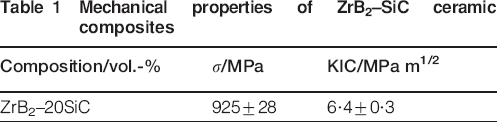
The mechanical properties of ZrB2–SiC (20 vol.-%SiC) ceramic composites (designated ZS for simplicity) are shown in Table 1. The powder composition of the Ti–Zr–Ni–Cu filler metal is 35Ti–35Zr–15Ni–15Cu (wt-%), which has an average particle size of 45 μm. The sizes of ZS are 8×6×6 and 20×10×6 mm respectively. Before the experiment, the surfaces to be brazed were polished with diamond paste and cleaned in ethanol and acetone. The stacked ZS/Ti–Zr–Ni–Cu/ZS assembly was brazed in a vacuum furnace (Centorr-3520). Vacuum brazing was performed in a vacuum of <1·0×10−2 Pa. The furnace was heated at the rate of 20°C min−1 to 920°C and kept for 10 min at that temperature. After brazing, all the specimens were furnace cooled to room temperature.
Mechanical properties of ZrB2–SiC ceramic composites
After the brazing, the joined plate was cut perpendicular to the joint interface, and the cross-section of the joint was polished with 0·5 μm diamond paste and cleaned in acetone. Microstructures and the elemental concentrations in the reaction zones were detected by SEM (S-4700) and energy dispersive X-ray spectroscopy (EDS; TN-4700). Phases present at the interfaces were identified by X-ray diffraction (XRD; D/max-rB). The ZS was removed step by step to reveal the interface beside ceramic substrate. After the removal of each layer, XRD analysis was carried out. The shear strength of the brazed joints was evaluated by an Instron-1186 mechanical testing machine with a constant speed of 0·5 mm min−1. The dimensions of samples for the shear test of ZrB2 based ceramics were 8×6×6 and 20×10×6 mm respectively.
Results and analysis
Products of interfacial reaction of ZS/Ti–Zr–Ni–Cu/ZS joint
Figure 1 shows the microstructures of ZS/Ti–Zr–Ni–Cu/ZS joint brazed with Ti–Zr–Ni–Cu brazing alloy at 920°C for 10 min, which revealed good wetting and intimate contact which led to defect free, well bonded joint. It can be clearly seen in Fig. 1a that three reaction zones have generated between ZS ceramics and Ti–Zr–Ni–Cu brazing alloy. A substantial interaction zone developed between ZS and filler metal. For the sake of convenience, the thin reaction zone beside ZS is called A zone containing bright area, which is the key to achieve the brazing. The middle area in the joint which contains many dark blocks is called C zone, and B zone is between A and C, which contains some light grey sticks and a few dark blocks. Figure 1b shows the major element content distributions (along the line indicated in the images) of ZS/Ti–Zr–Ni–Cu/ZS joint interface, which was brazed at 920°C for 10 min. Based on Fig. 1b, the content of element Ti was low in the A zone but it had one peak in the B zone. So it can be known that the element Ti was important for the interfacial reaction. It may form compositions with other elements in the joint. The content of element Zr was high in the A zone, even higher than that in ZS. So it was concluded that the zone perhaps was Zr based solid solution [named Zr(s,s)]. In the B and C zones, it declined gradually and fluctuated with distance away from the interface, which indicates that the element Zr may reactive with other elements. Si was few in A zone but there was a peak in B zone and a flat roof in C zone. There was thus evidence of dissolution and diffusion of Si from the SiC of the ZS into the liquid brazing alloy. The content of element Cu and Ni was low in A and B zones, but it was high as well as steady in C zone relatively. So it can be concluded that elements Cu and Ni reacted with Ti and Zr in C zone rather than participating in interfacial reaction.
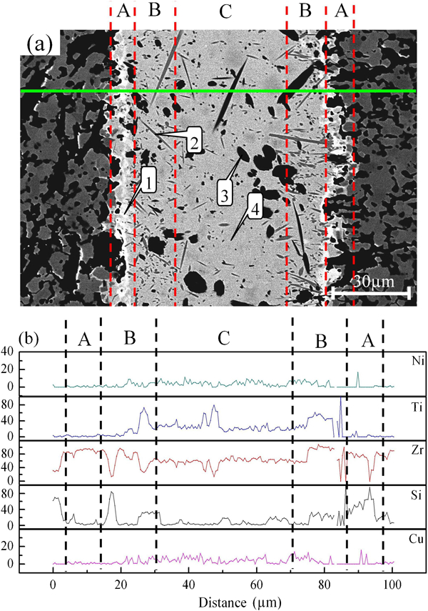
Image (SEM) of joint interface microstructure of ZS/Ti–Zr–Ni–Cu/ZS
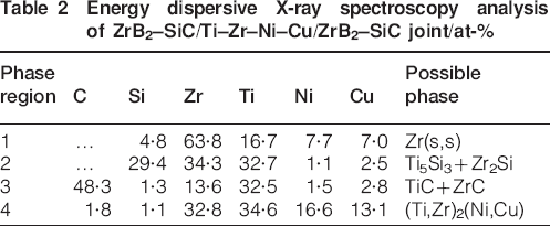
Table 2 represents the average chemical compositions of each point (as shown in Fig. 1a) on the brazed ZS/Ti–Zr–Ni–Cu/ZS joint. It can be seen from Table 2 that there were much Zr concentrations at point marker 1, soluting little elements Ti, Cu, Ni and Si. So it can be known that point marker 1 was Zr(s,s). The reaction products on point marker 2 were light grey sticks distributing in the interface, mainly containing elements Ti, Si and Zr. The products may be TixSiy and ZrxSiy according to Ti–Si and Zr–Si phase diagrams. On point marker 3, there were particles and dark blocks consisting of elements Ti, Zr and C, whose contents were ∼32·5, 13·6 and 48·3 wt-% respectively. It indicates that C from the SiC of the ZS dissolves and diffuses into the liquid brazing alloy. It was known that the Gibbs free energy of forming TiC and ZrC was negative at 920°C. The reaction of Ti and C, Zr and C can occur at 920°C respectively. So point marker 3 probably was TiC and ZrC phases. Point marker 4 may be Ti2Cu, Zr2Ni or Ti2Ni, Zr2Cu according to the EDS data.
Energy dispersive X-ray spectroscopy analysis of ZrB2–SiC/Ti–Zr–Ni–Cu/ZrB2–SiC joint/at-%
To verify the existence of phases in each zone, it was necessary to carry out the XRD pattern from the fracture surface of the brazed ZS/Ti–Zr–Ni–Cu/ZS joint. The joint was polished according to the direction paralleling to the interface. Then XRD pattern was carried out with these zones. The result of the XRD pattern is shown in Fig. 2. Figure 2a shows the XRD pattern of bright zone of ZS/Ti–Zr–Ni–Cu interface. The layer was mostly Zr, ZrB2 and SiC. So it can be known that the ZS/Ti–Zr–Ni–Cu interface was Zr(s,s). Figure 2b shows the XRD pattern of light grey sticks and a few dark blocks, and this layer was mostly Ti5Si3 and Zr2Si, as well as a little TiC and ZrC. Figure 2c shows the XRD pattern of C zone, and this layer was mostly (Ti,Zr)2(Ni,Cu), as well as a little TiC and ZrC.
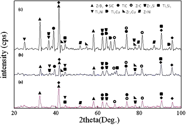
X-ray diffraction results of joint interface reaction layers (920°C, 10 min)
From the above, it can be concluded that the interfacial structure was ZS/Zr(s,s)/Ti5Si3+Zr2Si+TiC+ZrC+(Ti,Zr)2(Ni,Cu)/Zr(s,s)/ZS of the joint brazed at 920°C for 10 min.
Interface evolution mechanism of ZS/Ti–Zr–Ni–Cu/ZS joint
A conceptual interface evolution model for the ZS/Ti–Zr–Ni–Cu/ZS brazed joint is displayed in Fig. 3. The whole reaction process can be divided into three stages:
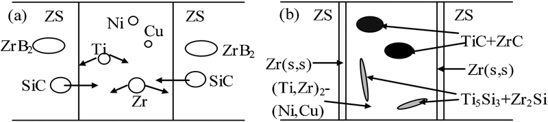
Interface evolution model
physical contact of filler metal with base materials and the melting of filler metal: from the room temperature to the melting point of filler metal, the metal plastically deformed and gradually contacted with the base materials. Following the increased brazing temperature, filler metal began to melt
diffusion of atoms: when the brazing temperature was up to the melting point of 35Ti–35Zr–15Ni–15Cu, the filler metal began to melt. Ti element was more active than Zr, so it was easy to react with ZrB2 or SiC in the base metal and made Ti atoms prior diffuse into the base metal. In fact, only SiC diffused into the liquid state solder because there were not borides in the joint observed by EDS and XRD, as shown in Fig. 3a
further diffusion and forming the reaction layers: as Ti gathered to the
ZS/Ti–Zr–Ni–Cu interface, the concentration of Ti at the
interface increased. So Ti atoms could contact with the SiC, forming TiC and
Ti5Si3 as the following equation


With the process continuing, the content of Ti element reduced due to the reaction with SiC continuously at the interface, but the content of Zr element hardly changed. As a result, Zr reached interface and formed Zr based solid solution layer, whose thickness was nearly 2 μm. The residual elements in the joint formed (Ti,Zr)2(Ni,Cu), as shown in Fig. 3b.
Mechanical property of brazed ZS/Ti–Zr–Ni–Cu/ZS joint
The brazing temperature and holding time were main factors that affected the shear strength. As shown in Fig. 4, when the brazing temperature was <920°C and the holding time was <10 min, the shear strength was low (as shown in Fig. 4a and b). This was because the amount of atomic diffusion was low and the reaction was insufficient between the filler alloy and the base materials. The Zr(s,s) layer was thin and not continuous, especially, there were some brittle intermetallics at interface, such as Ti5Si3 and Zr2Si (as shown in Fig. 4c). With the increasing brazing temperature or holding time, the shear strength increased.
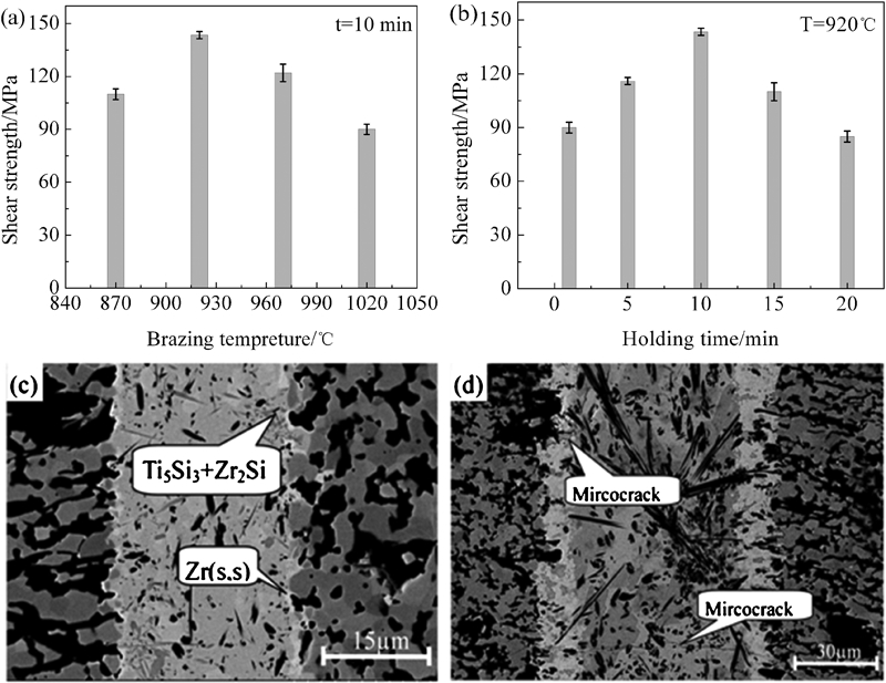
Effect of parameters on shear strength of ZS/Ti–Zr–Ni–Cu/ZS joints
The shear strength of the joint achieved a maximum (143·5 MPa) when the brazing temperature was 920°C and the holding time was 10 min. With further increasing brazing temperature or holding time, the shear strength decreased. This was because the interface was so thick that residual stress caused by mismatch of the coefficient of thermal expansion and the Young's modulus between the filler alloy and the base materials was too big, which helped form mircocracks in the joint. In addition, a further increase in the brazing temperature or the holding time made excessive intermetallics form in the joints (as shown in Fig. 4d).
Conclusions
ZrB2–SiC ceramic composites could be brazed using Ti–Zr–Ni–Cu active filler metal at 920°C for 10 min, which revealed good wetting and intimate contact which led to defect free, well bonded joint. The reaction products of brazed joint were mainly Ti5Si3, Zr2Si, TiC, ZrC and (Ti,Zr)2(Ni,Cu), the interfacial structure was ZS/Zr(s,s)/Ti5Si3+Zr2Si+TiC+ZrC+(Ti,Zr)2(Ni,Cu)/Zr(s,s)/ZS and the interface evolution mechanism of ZS/Ti–Zr–Ni–Cu/ZS joint could be divided into three stages: physical contact of filler metal with base materials and the melting of filler metal; diffusion of atoms; and further diffusion and forming of the reaction layers. The maximum shear strength of the joint was 143·5 MPa at 920°C for 10 min and the fracture type of ZS/Ti–Zr–Ni–Cu/ZS joint was brittle fracture and the fracture region was ZrB2 based ceramic composites near the interface.
Footnotes
Acknowledgements
This work was supported by the National Science Foundation of China (grant no. 51075101).