
Abstract
The present paper investigated the grain and texture characteristics in a nanostructured oxide dispersion strengthened ferritic steel subjected to friction stir welding. The ‘onion rings’ structure obviously exhibited in the macrostructure overview of the welds. The electron backscatter diffraction (EBSD) work revealed that the ‘onion rings’ comprised alternate layers made by coarse and fine grains, while no strong texture was exhibited in the alternate layers of the ‘onion rings’. Image quality maps of EBSD indicated that layers of fine grains were deformed under high strain conditions. Textures within the stir zone and thermomechanically affected zone were weak and exhibited some characteristics of bcc simple shear textures. Results of grain boundary revealed that the mechanical action in welding process promoted the transformation of low angle to high angle boundaries and contributed to the grain refinement.
Keywords
Introduction
Nuclear materials demand special standards of performance and quality. Oxide dispersion strengthened (ODS) ferritic steels possess excellent resistance not only to neutron irradiation induced swelling, but also to high temperature creep.1– 4 Therefore, these alloys are widely considered to be promising candidate materials for cladding of advanced fast reactors, as well as for first wall and blanket structural materials of fusion reactors. 5 5,6
In order to apply these alloys to large and complicated structures, joining is an inevitable and essential processing step. It has been found that conventional fusion welding methods can disturb the dispersion of the fine oxide particles in the alloy.7 As the excellent creep resistance and the neutron radiation resistance of ODS alloys are mainly due to the ultrafine oxide particles,8– 11 fusion welding methods are not applicable and should be substituted by better welding methods. The hot isostatic pressing is sometime considered as a joining method for ODS materials, but the limitation of size and cost is a critical challenge of this method. Consequently, friction stir welding (FSW), which is a solid state joining process, have been considered to be an alternative and promising way to weld ODS alloys. 7 7,12 So far, there has been few works on FSW of ODS alloys. The limited investigations in this field are mainly concerned with the weldability, the mechanical property and the microstructure. 7 12 7,12,13 Comparatively, analyses of the grain characteristics and the textures produced during FSW of ODS ferritic steels are much more limited.
The present study aims to promote understanding of the grain characteristic and the texture evolution of a nanostructured ODS ferritic steel joint, by direct examination of the friction stir welded sample using electron backscatter diffraction (EBSD) analysis.
Experimental procedure
The alloy of the present study was a nanostructured ODS ferritic steel produced by mechanical alloying method. This ODS alloy was developed as a fuel cladding material of Fast Breeder Reactor (FBR) in China.14 The nominal chemical composition was Fe–0·40C–13·60Cr–2·70Ti–0·34Mo–0·42Y2O3–0·44O–0·025N (wt-%). A bar of the ODS steel was heat treated at 1323 K for 1 h, followed by air cooling, and was then forged into a plate at 1323 K. The plate was cut into a specimen with dimensions of 500×30×3·5 mm, and then subjected to FSW in a bead on plate configuration. Welding was performed using a device of FSW-3TS-006 made by China FSW Center. The FSW tool, which was made of W–Re alloy, had a shoulder diameter of 12 mm, pin diameter of 3·5 mm and 3·1 mm pin length. The tool was tilted 2° from the vertical direction during the welding process. The traverse and rotation speeds used were 30 mm min−1 and 150 rev min−1. Observations were undertaken on the transverse cross-section of the welds by optical microscopy and EBSD at Hokkaido University of Japan. The EBSD work was performed using a JOEL JSM-6500 field emission scanning electron microscope with EBSD system, and the data processing was carried out by TSL Data Analysis 4·5 software.
Results and discussion
Macrostructure
Macrostructure of the friction stir welded ODS steel joint is shown in Fig. 1. The welded cross-section appears like a basin, and no volumetric defect is observed. The macrostructure of the weld can be split into several distinct regions 15 15,16 such as the stir zone (SZ), the thermomechanically affected zone (TMAZ), the inner or high temperature heat affected zone (H-HAZ), the low temperature heat affected zone (L-HAZ) and the base metal (BM) itself. Even in this low magnification overview, the typical ‘onion rings’ structure of friction stir joint can be obviously presented. The ‘onion rings’ structure is asymmetric and displays visible layers of varying thickness on the advancing side of the SZ and TMAZ.
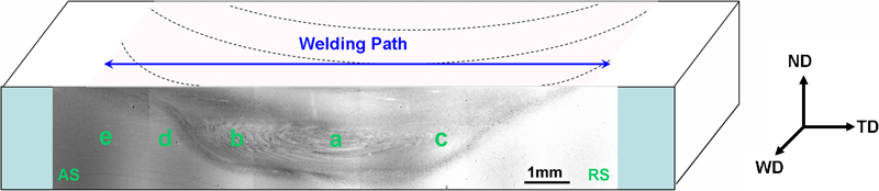
Macrostructure of friction stir welded ODS steel joint (a: SZ; b and c: TMAZ; d: H-HAZ; e: L-HAZ; AS: advancing side; RS: retreating side)
Grain morphology
The grain shape and crystal orientation within different zones of the joint are presented in Fig. 2. A typical hot forging microstructure within BM is obviously presented in Fig. 2a. The deformed matrix within BM comprises grains with a mean size of ∼1 μm, while most of the grains have the preferred direction in 〈001〉. When combined with the texture component maps (Fig. 3), the preferred crystal orientation of grains within BM can be determined as {110}〈001〉. Compared with BM, some of the grains grow bigger in HAZ, and the grain orientations obviously change (Fig. 2e and f). In particular, in H-HAZ almost all the coarse grains have different crystal orientations from BMs. As the metal in HAZ has not been affected by the stir tool during welding process, these changes can be mainly attributed to the effect of welding thermal cycle. During the welding process, the nuclei in HAZ grow in order to consume or release the stored energy of the surrounding deformed matrix.
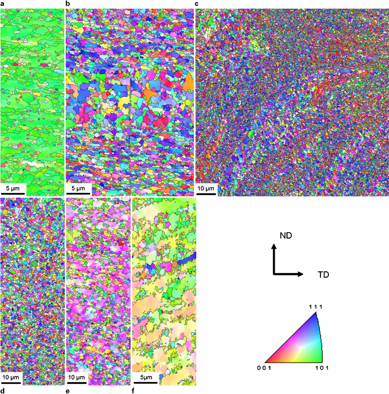
Grain morphology and crystal orientation images at different regions
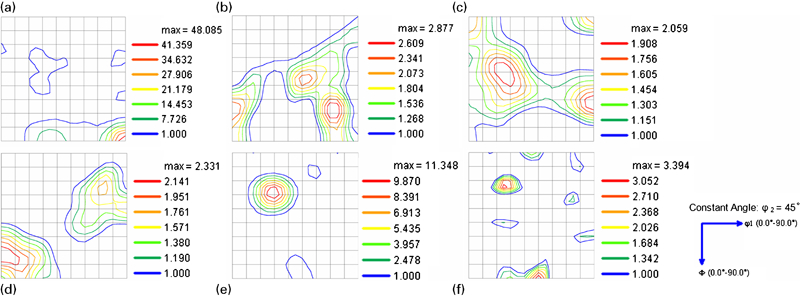
Orientation Density Function (ODF) sections at different regions of welds
In low magnification (Fig. 1), the ‘onion rings’ structure in ODS joint seems to have no obviously difference with the structure in aluminium alloy joint. 17 17,18 However, the EBSD data in SZ and AS-TMAZ (Fig. 2b and c) show that the ‘onion rings’ structures comprise alternate layers which are obviously made by coarse and fine grains. In particular, both of the coarse and fine grains are oriented much randomly with few preferred orientations. These phenomena could be mainly attributed to the plastic flow of the transferred metal during welding process. The transferred metal, which is driven by the tool shoulder and stir pin, flows layer by layer.18– 20 Inevitably, complicated interactions could be formed among different layers. As the interactions are inhomogeneous, the non-uniform deformations and plastic strains could be induced among different layers. Therefore, the grain states within each layer could be varied. Grains within the layers deformed under high strain conditions could be smaller than those within the regions deformed under low strains. More evidences can be found in the image quality (IQ) maps. Figure 4 shows the IQ maps of SZ and AS-TMAZ respectively. In sharp contrast to the coarse grains, the fine grains within SZ and AS-TMAZ present darker patterns in IQ maps, which reflect higher strains in those fine grains. According to those analyses, the unobvious layered structures within RS-TMAZ reveal that the plastic deformations in this region are not as drastic as the deformations occurred in SZ and AS-TMAZ. Furthermore, during FSW process, the temperatures from poison to poison within the welds are also varied. Even in the equidistant positions from the welding line, the temperatures are different between AS and RS. The complicated temperature distribution could also affect the plastic flow and plastic deformation of the transferred metal, and lead to varied nucleation and grain growth within different layers.
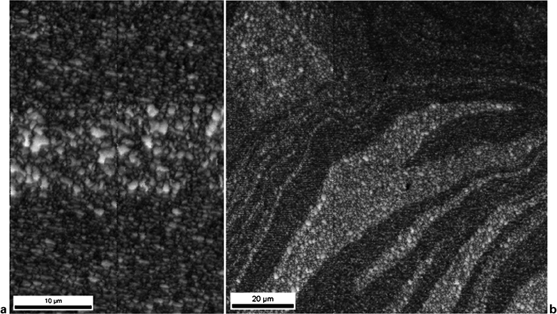
Image quality maps at different regions
Grain boundary
Misorientation angle histograms are shown in Fig. 5. The contrast of these figures reveals distinct characteristics within different regions of the welds. Figure 5a corresponding to BM shows a bimodal distribution, with a high population of HABs (high angle boundaries with misorientation angles more than 15°) and LABs (low angle boundaries with misorientation angles between 2 and 15°). The high population of LABs is fully consistent with the Inverse Pole Figure (IPF) maps shown in Fig. 2 for the BM case. In addition, the high fraction of grains with misorientations near 60° could indicate the existence of a high density of special boundaries such as sigma-3, which is a characteristic of twinning. The high level of twinning within BM can be attributed to the hot forging process during the preparation of experimental samples. Although HAZ borders the BM, grain boundaries within HAZ display a radically different trend. As the regions within HAZ are not affected by the welding force imposed by the stirring tool during welding process, the change of the grain boundaries within HAZ could be only attributed to the welding thermal cycle.
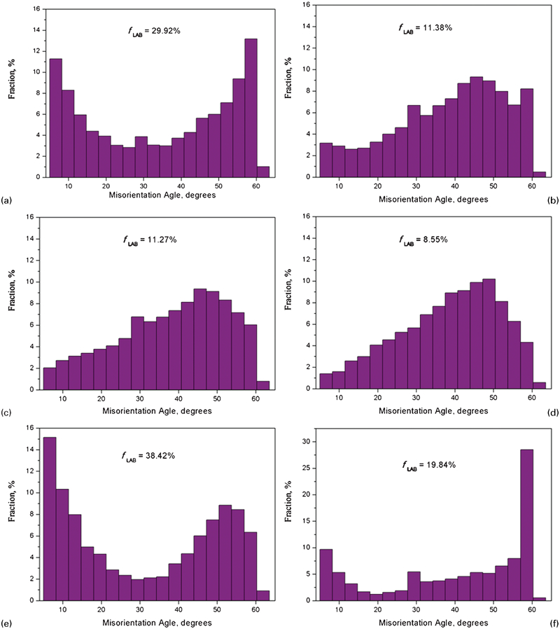
Misorientation angle histograms at different regions
The misorientation angle histograms of SZ, AS-TMAZ and RS-TMAZ are shown in Fig. 5b–d. Some similarities in boundary characteristic can be found in these regions. When comparing these regions with the BM and HAZ, the fractions of LABs within these regions are much lower. Remarkably, although TMAZ borders H-HAZ, they varyingly contain the lowest and the highest fraction of LABs respectively. As these two regions are adjacent, the temperature difference is not the primary factor to vary the fractions of LABs within these two regions. Actually, the radical difference between the low LABs regions (SZ and TMAZ) and the high LABs regions (BM and HAZ) is that the material within low LABs regions has undergone complicated plastic deformation imposed by the stir tool. This strongly hints that the plastic deformation within SZ and TMAZ could promote the transformation of boundaries from LABs to HABs. As the HABs have the segregation effects at grain boundaries, the grains within SZ and TMAZ become finer than the initial grains. These analyses coincide well with the former finding of the grain refinement phenomenon within SZ and TMAZ in Fig. 2.
Texture
The FSW process produces a complicated microstructure consisting of widely varying crystallographic textures from poison to position through the welds. The local texture and the texture gradient offer information on the deformation history of the material in that region. Various zones throughout the weld are isolated independently in an attempt to identify the local texture and compare with others. As shown in Fig. 3a, the BM contains a dominant {110}〈001〉 texture with the highest intensity of ∼48 times random. This strong texture has a typical characteristic of deformation by forging and pressing in bcc metals.
Based on the texture component maps (Fig.
3), strong texture gradients can be observed from the BM to HAZ. The
dominate textures within L-HAZ (Fig.
3f) contain {110}
 and
{113}
and
{113}
 components. The observation of those new
textures within L-HAZ indicates that the {110}〈001〉 texture within
the BM is unstable, even the low temperature in L-HAZ could trigger the change.
Compared with L-HAZ, the texture within H-HAZ (Fig.
3e) almost changes to {113}
components. The observation of those new
textures within L-HAZ indicates that the {110}〈001〉 texture within
the BM is unstable, even the low temperature in L-HAZ could trigger the change.
Compared with L-HAZ, the texture within H-HAZ (Fig.
3e) almost changes to {113}
 instead
of {110}
instead
of {110}
 and has an strong intensity about 11 times
random. As the material in HAZ only undergoes a thermal cycle and is not affected
by the plastic deformation, the changes of the textures within H-HAZ and L-HAZ
can be attributed to the affected heat. In L-HAZ, as the temperature is lower
than other welding zones, the dominate texture of BM {110}〈001〉
presumably converts to {110}
and has an strong intensity about 11 times
random. As the material in HAZ only undergoes a thermal cycle and is not affected
by the plastic deformation, the changes of the textures within H-HAZ and L-HAZ
can be attributed to the affected heat. In L-HAZ, as the temperature is lower
than other welding zones, the dominate texture of BM {110}〈001〉
presumably converts to {110}
 initially.
Because the texture {110}
initially.
Because the texture {110}
 and
initial texture {110}〈001〉 have the same crystallographic plane,
in this way the converted resistance or obstruction could be lower. As the
temperature increases on the path from L-HAZ to H-HAZ, the {110}
and
initial texture {110}〈001〉 have the same crystallographic plane,
in this way the converted resistance or obstruction could be lower. As the
temperature increases on the path from L-HAZ to H-HAZ, the {110}
 texture could be gradually
converted to {113}
texture could be gradually
converted to {113}
 .
.
Surprisingly, SZ and TMAZ (Fig. 3b–d) exhibit no strong texture. The highest texture intensity of there regions is just about 2·8 times random. These observations are obviously different from the results found in friction stir welded aluminium alloys which always exist noticeable gradients and strong intensities within SZ and TMAZ.20 Associated with the obvious observation of ‘onion rings’ structure in Fig. 1, it can be inferred that the ‘onion rings’ structure in the welds can be formed and visually observed in macrostructure, while there is no strong texture or strong texture gradient in the structure. In other words, neither the strong texture nor the strong texture gradient is the necessary condition for forming the ‘onion rings’ structure in the friction stir welds.
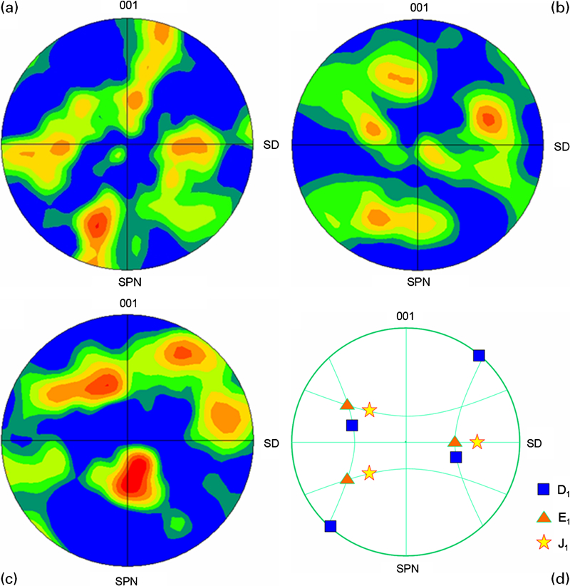
Remarkably, the strong texture of the initial metal with a typical characteristic of forging is replaced by complicated textures within SZ and TMAZ. The textures in these regions exhibit some characteristics of shear deformation. A more clear understanding can be obtained by comparing these textures with the ideal components of simple shear texture in bcc metals, as shown in Fig. 6. Textures within SZ comprise similar D1 component of the typical bcc simple shear textures. Textures within AS-TMAZ seem to match the bcc E1 shear texture component. Textures within RS-TMAZ have some resemblances with bcc J1 shear texture component. These similarities demonstrate that the material in SZ and TMAZ has undergone shear deformation, which is created by the stir tool shoulder and the submerged pin. Figure 6 also reveals that textures of these regions can not absolutely match the simple shear texture. The limited similarities demonstrate that there are more complicated deformations occurred in these regions, besides of the simple shear deformation. Particularly, by some suitable rotation of the pole figures (Fig. 6a–c), the textures can correspond better to the ideal components of simple shear texture (Fig. 6d), as Reynolds et al. 21 and Fonda et al. 22 22,23 found in friction stir welded titanium alloys. The direction and quantity of the suitable rotation presumably depends on many factors, such as the non-uniform welding temperature, the upsetting force during welding and the pressure created by the stir tool in transversal direction.
Conclusions
The microstructures and crystallographic textures of a nanostructured ODS ferritic steel joint welded by FSW were studied using EBSD. Local textures and grain characteristics within different regions of the welds were analysed and compared. The textures within SZ and TMAZ were correlated with the bcc simple shear textures. The main results are as follows.
Under the welding condition of the present study, the ODS welds visibly exhibits the typical ‘onion rings’ structure which comprises alternate layers with coarse or fine grains.
The layered structure can be mainly attributed to the non-uniform plastic deformation during welding. Grains within the layers deformed under high strain conditions are smaller than those deformed under low strains.
No strong texture is exhibited in the alternate layers of the ‘onion rings’ structure. Neither the strong texture nor the strong gradient in texture is the necessary condition for forming the ‘onion rings’ structure in the friction stir welds.
The textures within SZ and TMAZ present some similarities with the bcc simple shear texture.
Stir zone and TMAZ contain much less LABs than the zones (BM and HAZ) without the influence of mechanical force. The mechanical effect of the stir tool during welding process promotes the transformation of boundaries from LABs to HABs and contributes to the grain refinement.
Footnotes
Acknowledgements
This work was supported by the National Natural Science Foundation of China (grant no. 50971030), the National Basic Research Development Foundation of China (grant nos. 2008CB717802 and 2009CB109004), the China Scholarship Council and the CUP Program in Japan. The authors would like to thank the staff of China FSW Center at BAMTRI (Beijing Aeronautical Manufacturing Technology Research Institute) for their support during the welding experiment. Wentuo Han would like to thank his friends in laboratory of advanced high temperature materials at Hokkaido University, Japan.