
Abstract
The ability to weld repair three precipitation hardening superalloys, i.e. Alloy 718, Allvac 718Plus and Waspaloy, with gas tungsten arc welding, is compared in this study. Four different solution heat treatment conditions for each material were examined: Alloy 718 and Allvac 718Plus heat treated at 954°C–1 h, 982°C–1 h, 954°C–15 h and 1020°C–1 h and Waspaloy for 4 h at 996°C, 1010°C, 1040°C and at 1080°C. By metallography, the total number of cracks was evaluated in both the heat affected zone and the fusion zone, which made it possible to consistently rate the repair weldability of these three materials. Alloy 718 was significantly the best one, with Allvac 718Plus slightly better than Waspaloy. As expected, the solution heat treatment conditions only affected the heat affected zone cracking behaviour.
Introduction
The introduction of superalloys, especially of the precipitation hardened type, in the hot section of aircraft engines improved the performance dramatically. The large and load bearing structures exposed to high service temperatures are today typically made of Alloy 718 or Waspaloy, where the very high strength is due to precipitation hardening. Alloy 718 achieves its strength through the γ″ phase precipitates, while Waspaloy benefits from the γ′ phase.1 A newly developed γ′ superalloy, Allvac 718Plus, is for the same reason of interest to the aerospace industry for such components.2 The repair weldability of these three alloys is investigated in the present study.
About 50 years ago, it became possible to investment cast high quality large diameter structural components by vacuum metallurgy. At the same time, Alloy 718 became well established as a preferred choice for large size aerospace applications due to its very high strength but not least to its good processability. The marriage between this alloy and the vacuum investment casting process became a standard selection as compared with the previous alternative of joining smaller parts into an assembly by welding. With the steadily increasing size of the largest structures and a strong desire to reduce the weight, there is, however, today a renewed interest in producing weld assembly parts.3
The rationale is the possibility to use higher strength wrought material, where geometry allows, and join these wrought parts with the cast material, where complex geometry is needed.
Basically, wrought material is less susceptible to cracking during welding than cast material due to the much smaller grain size and the fact that wrought material is more homogeneous. Consequently, most cracks are found in the cast part when it is joined to a wrought one.
In repair welding, irrespective if it is a cast, wrought or a combined part, the situation is often of similar complexity. Of course, if the welding is carried out on a wrought part, then the cracking in the heat affected zone (HAZ) in the parent metal is less severe than if the welding is carried out on a cast part. The first weld passes being deposited at weld repair will experience significant heat treatments from the following weld passes, and it is well known that the level of strain is building up sequentially. In essence, there is little benefit from the multiple welds except from the fact that the immediate input of heat can be reduced and allowed to dissipate before the next weld is added and thereby reduce the overall strain and the associated risk for cracking. Since most repair welding situations are unique, it is difficult to use preferred automatic methods, and the welding then rests on the skill of the most experienced welders. It goes without saying that individual skill is a serious arbitrary factor that adds to the complexity of the weld repair operation per se.
Considering the nature of the actual cracking at repair work, it can basically be divided into two categories: the cracking that takes place in the HAZ and the cracking that occurs in the fusion zone (FZ) weld deposits. The latter is often referred to as ductility dip cracking and takes place at lower temperatures. There is, however, a striking confusion about the actual mechanisms which are involved in these categories.4 Still, there is agreement on the fact that several factors work in the same way and thus may contribute in both categories. For example, impurity elements such as B, P and especially S are considered detrimental since they segregate to the grain boundaries where they may enhance eutectic liquation 5 5,6 as well as reduce the solid state cohesion at lower temperatures.4
The main difference between the alloys in the present study relates to strain age cracking (SAC) usually taking place upon reheating, which allows for hardening in highly stressed weld metal. SAC is the usual culprit of crack failure in the welding of fast hardening γ′ alloys, as is the case with Waspaloy and Allvac 718Plus alloys. Owing to the slow precipitation hardening of γ″, Alloy 718 is in contrast almost immune to SAC, while the Nb content makes it more vulnerable to HAZ cracking by the presence of Nb carbides, which allows for constitutional liquation.7 It is therefore expected that Waspaloy and Allvac 718Plus alloys are more susceptible to SAC at repair and preferably take place in bottom layer weld deposits as a consequence of the accumulated (aging) heat treatments exerted by following weld repair passes.
The main purpose of the present study is to investigate how various solution heat treatments affect the repair weldability relating to HAZ cracking of Alloy 718, Waspaloy and Allvac 718Plus. It is not expected to see any significant difference in the hot tearing behaviour in the actual weld deposits caused by the different heat treatments.
Experimental
Material
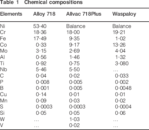
All the materials used were from double melted (VIM and VAR) wrought bars with the chemical composition shown in Table 1.
Chemical compositions
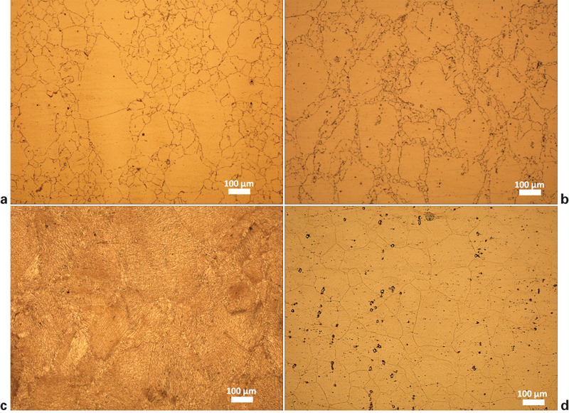
The as received microstructures are shown in Fig. 1 together with the intercept ASTM grain size ASTM 6, 5 and 7 and Vickers hardness 233, 415 and 356 HV for Alloy 718, Allvac 718Plus and Waspaloy respectively.
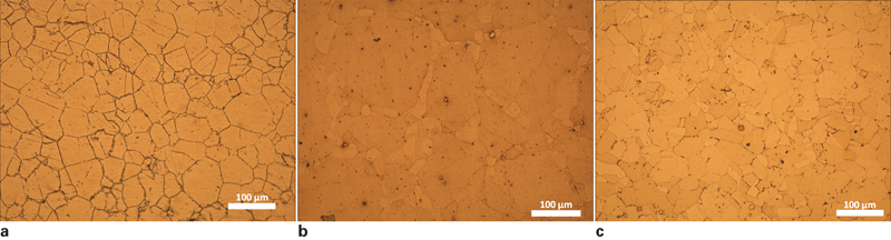
As received microstructure, ASTM grain size and Vickers hardness numbers
Heat treatments
Each bar was slightly machined to a diameter of 135 mm from which four discs with a thickness of 10 mm were cut and subjected to four different solution heat treatments in a vacuum furnace. Alloy 718 and Allvac 718Plus were heat treated at 954°C–1 h, 982°C–1 h, 954°C–15 h and 1020°C–1 h. Here, the 1 h treatments at 954 and 982°C are within the range given by the aerospace material specification. 8 8,9 The 15 h heat treatment at 954°C was carried out to produce a large amount of δ phase in both alloys. The 1020°C–1 h heat treatment was performed to produce a coarse grain size material without δ phase. For the Waspaloy, four different 4 h solution heat treatments were carried out at 996, 1010, 1040 and 1080°C and are all within the recommendation given by the aerospace material specification. 10 10,11 The two high temperature treatments were used to produce coarse grain size materials. In all the heat treatments, a heating rate of 0·3°C s−1 was used and with enforced argon gas cooling down to 500°C to minimise precipitation.
Repair welding
After the heat treatments, repair grooves (four elongated and five circular) were machined into each disc, as illustrated in Fig. 2a. The circular grooves had a diameter of 10 mm and a depth of 5 mm. The elongated ones had a length of 20 mm, width of 10 mm and depth of 5 mm. The discs were finally welded onto 25 mm thick stainless steel discs to maximise the restraint factor during repair (Fig. 2c). The grooved test plates were cleaned thoroughly in alkali solution before welding. Repair was performed manually using gas tungsten arc welding technique, with Ar gas for protection, by experienced welders, with the overview result as illustrated in Fig. 2b. Filler weld wires with matching chemistries were used. Weld current was limited to a maximum of 65 A on the welding equipment but adjusted to meet the judgment of the welder for a repair work of this kind. Twenty weld passes were made for each groove on average to minimise the heat input for each pass. Post-weld quenched by air was exercised before the next pass was made.
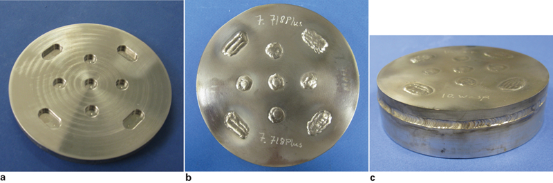
Overview of test plate design and fixturing
Weld examination
Metallographic mounts of cross-sections were made for all the weld repairs (264 cross-sections in total): 22 for each material condition, three for each of the elongated and two for the round welds. After standard grinding and polishing procedures, the mounts were electrolytically etched in oxalic acid at ∼4 V for about 3–6 s. The number of cracks in the HAZ of the base metal as well as in the actual weld FZ was counted at ×200 magnification in a light optical microscope. Light optical microscopy as well as scanning electron microscopy (SEM) was used for examining the microstructure. SEM imaging was carried out using both secondary and backscattered electron (BSE) operating modes at 20 kV accelerating voltage. Energy dispersive X-ray (EDX) spectroscopy was also used to verify certain phase constituents. Micro-Vickers hardness tests (1 kgf) were carried out at three distances from the surface to reveal if any hardening takes place during the successive weld repair. These hardness numbers are shown as an average of five indents together with standard deviation for each respective surface distance.
Results
Heat treatments
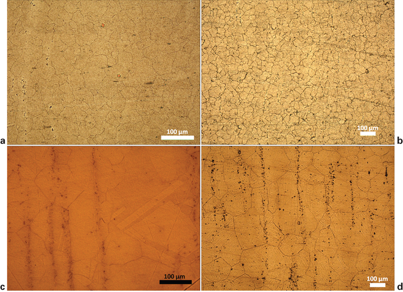
The microstructure, hardness and grain size response to the four different heat treatments of Alloy 718 are shown in Fig. 3. The microstructure responses to these heat treatments were as expected.12 It is evident that no or very little changes have taken place at the 954°C–1 h treatment (ASTM 6 and 245 HV) in Fig. 3a when compared with the as received material shown in Fig. 1a. The amount of δ phase increases with increasing dwell time at that temperature and is significant after 15 h (ASTM 5 and 243 HV), as evidenced in Fig. 3b. At 982°C, the δ phase is partly dissolved after 1 h (ASTM 6 and 258 HV), as seen in Fig. 3c. The supersolvus δ treatment at 1020°C for 1 h (ASTM 5 and 235 HV) brings a clean structure free from δ phase, which makes the MC carbides more clearly visible. Concomitant grain growth by one ASTM number has taken place (Fig. 3d).
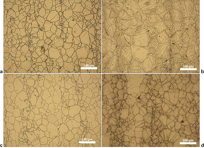
Microstructures, hardnesses and ASTM grain sizes of Alloy 718 at different solution heat treatments
The microstructure, hardness and grain size response to the different solution treatments of Allvac 718Plus are shown in Fig. 4. There is no clear difference between the 954°C–1 h (ASTM 5 and 422 HV) and the 982°C–1 h (ASTM 6 and 355 HV) treatments except that the hardness value is lower for the latter. As with Alloy 718, a substantial amount of δ phase has precipitated at the 954°C–15 h treatment (ASTM 5 and 405 HV). As in Alloy 718, the supersolvus treatment reveals a clean microstructure and a coarse grain size (ASTM 3 and 360 HV). The bimodal grain structure of the as received material has partly disappeared during the grain growth.
Microstructures, hardnesses and grain sizes (ASTM) of Allvac 718Plus at different solution heat treatments
In Fig. 5, the results for Waspaloy are shown, where it is evident that substantial grain growth has occurred at the two highest temperature heat treatments [1040°C–4 h (ASTM 3 and 354 HV) and 1080°C–4 h (ASTM 2 and 357 HV)]. At the two lower temperatures [996°C–4 h (ASTM 6 and 372 HV) and 1010°C–4 h (ASTM 6 and 368 HV)], no change of the microstructure is obvious. There are small hardness differences irrespective of heat treatment and despite the coarse grain, which is expected to reduce the hardness. A detailed discussion on this can be found elsewhere.12
Microstructures, hardnesses and grain sizes of Waspaloy at different solution heat treatments
Repair welding
In Fig. 6, an etched cross-section of a weld repaired groove is shown. It is clearly seen that many weld deposits (∼20 weld passes) are needed to fill a 5 mm deep groove of this kind. The deposited material seen here is in the following referred to as the FZ.
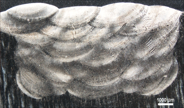
Macroimage of etched cross-section of 5 mm deep repaired groove with several weld deposits
HAZ cracking
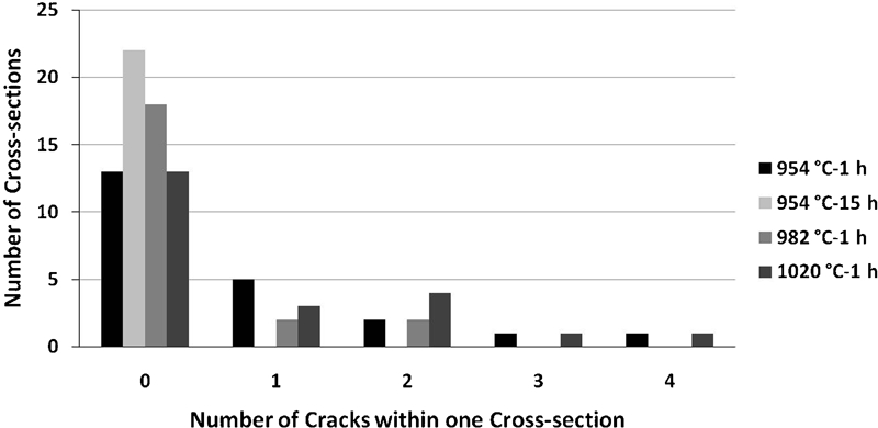
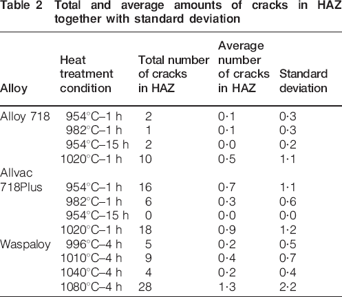
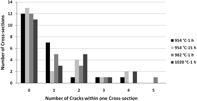
The frequencies of cross-sections with the same amount of cracks found in the HAZ beside the FZ of the wrought base material for all three alloys and heat treatment conditions are shown in Figure 7 Figure 8 Figs. 7–9. The total and average amounts of cracks in the HAZ together with the standard deviation for each specific heat treatment condition are shown in Table 2. The largest numbers of cracks, irrespective of material, are found in the conditions obtained by the heat treatments at the highest temperatures.
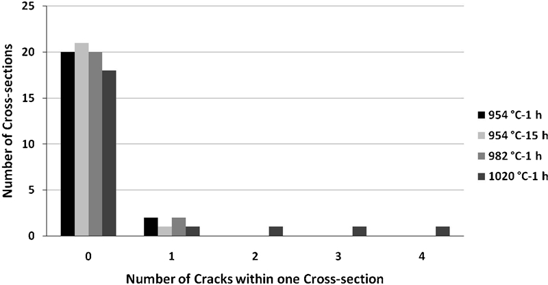
Frequencies of cross-sections with same amount of cracks in HAZ of Alloy 718 in different solution heat treatments conditions
Frequencies of cross-sections with same amounts of cracks in HAZ of Allvac 718Plus in different solution heat treatments conditions
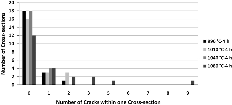
Frequencies of cross-sections with same amounts of cracks in HAZ of Waspaloy in different solution heat treatments conditions
Total and average amounts of cracks in HAZ together with standard deviation
Fusion zone cracking
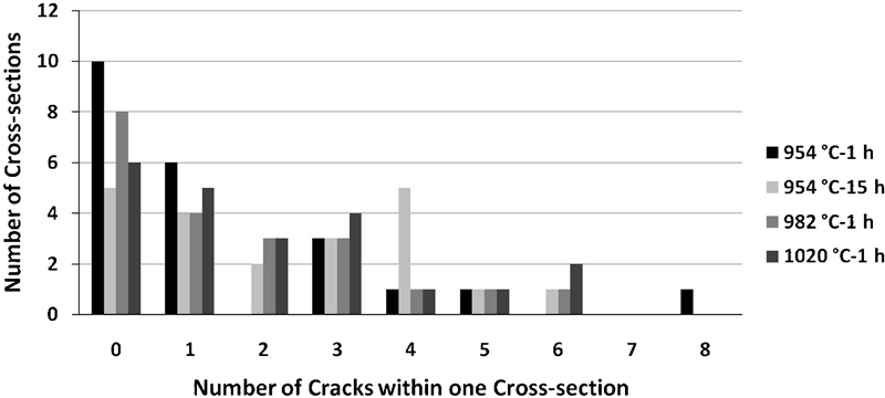
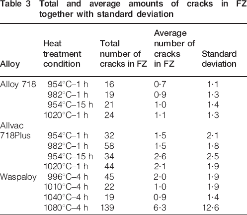
In Figure 10 Figure 11 Figure 12 Figs. 10–13, the frequency distribution of FZ cracking is shown. The total and average amounts of cracks in the FZ together with standard deviation for each specific heat treatment condition are shown in Table 3. The nature of the cracking is here less clear compared with the HAZ cracking. However, the high temperature solution heat treatment in Waspaloy shows a remarkable high number of cracks in comparison (Fig. 13).
Frequencies of cross-sections with same amounts of cracks in FZ of Alloy 718 in different solution heat treatment conditions
Frequencies of cross-sections with same amounts of cracks in FZ of Allvac 718Plus in different solution heat treatment conditions
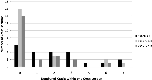
Frequencies of cross-sections with same amounts of cracks in FZ of Waspaloy in different solution heat treatment conditions
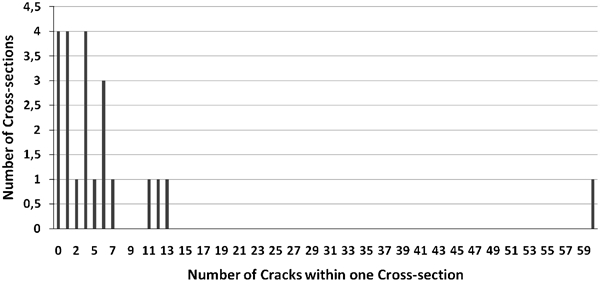
Frequencies of cross-sections with same amounts of cracks in FZ of Waspaloy 1080°C–4 h condition
Total and average amounts of cracks in FZ together with standard deviation
Microhardness tests were carried out at three distances from the surface (Fig. 14) to reveal if any hardening takes place during the successive weld repair. These hardness numbers are shown as an average of five in Table 4.
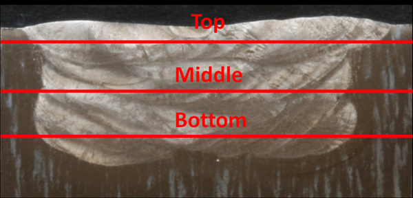
Weld repaired groove with three locations indicated at which microhardnesses were measured
Hardness measurements at bottom, middle and top parts of repair weld in Alloy 718, Allvac 718Plus and Waspaloy
Discussion
HAZ cracking
In Figure 7 Figure 8 Figs. 7–9, it is clearly seen that the risk of cracking in HAZ in the coarse grain material is significantly higher than in the finer grain materials during repair welding. This response agrees well with the general acknowledged effect of coarse grains on weldability.4 However, it should be noted that the difference in grain size, especially for Alloy 718, is not great but nevertheless reveals a pronounced cracking susceptibility. The rationale can be split into two parts. The first part is that the grain boundaries of such a material are more vulnerable to cracking due to fact that they have to accommodate for larger localised strains compared with a material with smaller grains strained to the same level.4 The second part of the rationale is the fact that all the materials encompass a specific grain boundary area, which decreases with increasing grain size. Thus, the concentrations of trace elements that favour grain boundaries as B, P and S are likely to be higher in a coarse grain material.5 This is concomitant with the well known fact that the boundaries of a large grain ‘burnt material’ have become brittle due to the accumulation of trace elements by the ‘sweeping action’ of mobile boundaries at the highest temperatures as e.g. utilised in the zone refining technique to get rid of small amounts of impurities.13
Since there are 22 cross-sections of welds examined for each material and heat treatment condition and the total number of cracks summarised for the 22 sections often are just a few, it is obvious that HAZ cracking must be absent in many sections, and in fact, the majority of the cross-sections have no cracks at all. However, the 1020°C–1 h condition for Alloy 718 and Allvac 718Plus as well as for the large grain size condition of Waspaloy heat treated at 1080°C–4 h differs in this respect from the others by typically having several cross-sections with one or a few cracks each.
A beneficial effect of the δ phase on the HAZ cracking for Alloy 718 and Allvac 718Plus may be anticipated by comparing the total number of cracks for the condition with a large amount of δ phase (954°C–15 h, Figure 3 Figs. 3b and 4c respectively) with the number of cracks for the material with a limited amount δ phase produced by the standard solution heat treatment at 954°C–1 h. It should again be noted that the total number of cracks are very few, especially for Alloy 718, and such an anticipation is at best qualitative rather than quantitative, though for Allvac 718Plus, the facts are more convincing. Still, this agrees with earlier observations about a beneficial influence of δ phase associated with a backfilling mechanism and grain boundary pinning. 12 12,14 Boucher et al. also found that δ phase improved the resistance to HAZ liquation cracking through a solute blocking mechanism of Nb.15 Others have claimed that the δ phase will increase the susceptibility to cracking through liquation and embrittlement of the grain boundaries at elevated temperatures. 16 16,17
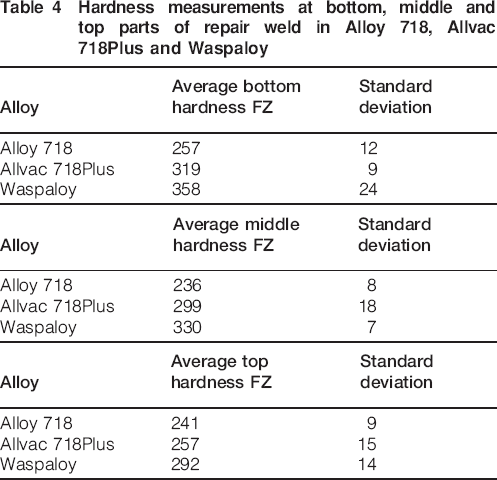
Both Alloy 718 and Allvac 718Plus contain NbC carbides, which form a low melting carbide eutectic at ∼1250°C at the grain boundaries. 18 18,19 The NbC carbides may also produce a low melting Laves eutectic at ∼1160°C through constitutional liquation. 6 7 6,7,19 This is clearly shown in Fig. 15b. In Fig. 15a, a crack within the HAZ is seen together with liquated Ti and Nb rich carbides (verified by SEM-EDX) at the grain boundary for Allvac 718Plus. In Fig. 15b, traces of a Laves eutectic, also supported by SEM-EDX analysis, beside carbides indicate that a constitutional liquation of NbC has occurred.
Images (SEM-BSE) showing a grain boundary liquation in Allvac 718Plus and b constitutional liquation of NbC phase with Laves eutectic in Alloy 718
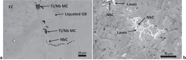
Both Alloy 718 and Allvac 718Plus contain local accumulations of NbC carbides, identified by SEM-EDX analysis, in the shape of strings as a reminiscence of the ingot segregation of Nb and the elongation during the forging of the ingot into the bar stock. At lower magnification (Fig. 16a), the segregation pattern is seen enhanced by the etching.
a, b MC carbide stringers in Alloy 718 at low magnification within parent metal and c SEM-BSE image of carbide liquation beside FZ
Surprisingly, there is no exaggerated grain boundary liquation associated with these stringers even though NbC liquation do occur in the HAZ, as indicated for Alloy 718 in Fig. 16. Since the details of the sequence of heating cycles can at most be speculated about, it is difficult to make any firm conclusions from this observation, although the temperature gradient, not surprisingly, must have been very steep in the mushy zone between the completely melted filler material and the wrought bar stock material with the obvious strings of carbides.
In addition, for Waspaloy, the condition which seems to be most sensitive to HAZ cracking is the coarse grain condition obtained by the highest temperature at 1080°C for 4 h. As before, the main cause of the susceptibility is believed to be the influence of the large size of the grains. As indicated in Fig. 17a and confirmed by SEM-EDX spectroscopy, TiC may liquate at the eutectic temperature of ∼1350°C12 or possibly in interaction with the melt in the adjacent mushy zone. This is a most probable reaction, which may explain the liquation along the grain boundaries which appears to be a carbide string in Fig. 17b.
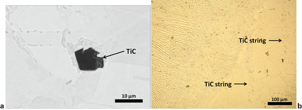
a image (SEM-BSE) revealing grain boundary liquation and liquation of MC phase in Waspaloy together with light optical microscope image of b TiC phase stringer as indicated by arrows
Fusion zone cracking
In Figure 10 Figure 11 Figure 12 Figs. 10–13, the total number of FZ cracks is shown for all four heat treatment conditions for the three alloys. As before, the total numbers of cracks on 22 cross-sections are shown, and thus, on average, few cracks can be found on each individual section. Taking the complexity of the weld process into consideration, a considerable scatter can be expected. Epitaxial growth occurs within the deposits beside the substrate material and acts as a connection with the FZ. Cracking is not expected to be influenced by the heat treat condition of the substrate material except possibly in the filler deposits very close to the substrate material.
The difference in the number of FZ cracks between the four different conditions of Alloy 718 as well as of Allvac 718Plus, as shown in Figure 10 Figs. 10 and 11 respectively, must thus be explained by the scatter related to the actual process of repair.
However, for Waspaloy, the very high number of cracks detected for the 1080°C–4 h condition in comparison with the other conditions, as evident in Figure 12 Figs. 12 and 13, is very striking and therefore merits closer examination. As already stressed, many cross-sections exhibit very few or no cracks. This is clearly illustrated in the frequency diagram of Fig. 13. The 1080°C–4 h condition is the only condition revealed to possess more than seven cracks within one single weld cross-section.
It is obvious that something extraordinary has taken place for the 1080°C–4 h condition and the samples belonging to the right hand side tail of Fig. 13. Each of these four cross-sections belonged to one of four individual weld repaired grooves: three rectangular and one circular. It was not possible to detect any metallurgical differences at the cracks between these four samples and other samples, which could be related to other causes than variations of the weld process. It is also striking that in one single cross-section, 60 cracks were found, which is extraordinary in comparison. This indicates that the welding procedure went awry in some way or another at this occasion.
There are many different parameters which could influence such increased cracking behaviour, e.g. parameters associated with the filler weld wire, the gas protection and several other process parameters as the intervals between each weld deposit (cooling time) and the way the experienced welder position and move the welding torch.
The FZ cracking was primarily intergranular at migrated grain boundaries, as seen in Fig. 18.
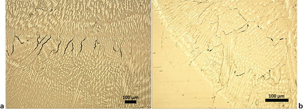
Fusion zone weld cracking in Waspaloy at migrated grain boundaries; (a) within the FZ and (b) within the FZ adjacent to the HAZ
Such migrated grain boundaries are clear signs of the profound effect that subsequent welds have on the previous ones.4 This is also reflected by the hardness values shown in Table 4. The bottom layers of Allvac 718Plus and Waspaloy have clearly higher hardness values compared with the middle and top layers, while this is not the case for Alloy 718. The explanation relates to the fact that the rate of hardening for Alloy 718 is more sluggish, and the heat treatment imposed by subsequent welds allows for hardening in the Waspaloy and in Allvac 718Plus but not in Alloy 718, which clearly indicates the hurdle for welding γ′ phase hardened superalloys and is manifested as SAC.
It is not unreasonable to claim that the majority of cracks in the repair welding of Waspaloy are associated with SAC, whereas the cracking in the FZ and HAZ of Alloy 718 is mainly related to solidification and HAZ liquation. It is more difficult to make such a general assumption for Allvac 718Plus since this alloy shows a slightly more sluggish hardening response in comparison with Waspaloy, as indicated by the hardness values in Table 4.
In Fig. 19, the total numbers of cracks in the FZ and HAZ of Alloy 718, Allvac 718Plus and Waspaloy are compared. It should be emphasised that this ranking also reveals what has been experienced in the repair workshop. Note that even though the cracks have been classified into two categories as where they were found, HAZ versus FZ cracking, this does not mean that the mechanisms of cracking cannot overlap. SAC can take place both within the HAZ and FZ. Owing to the absence of Nb in Waspaloy, fewer problems are related to solidification cracking and eutectic grain boundary embrittlement, as was shown by varestraint testing in a previous study, where Waspaloy surprisingly indicated superior weldability over both Alloy 718 and Allvac 718Plus.19 However, since the varestraint testing does not include SAC, it is felt that the results of this weld repair study more truly reflect the weldability of these superalloys.
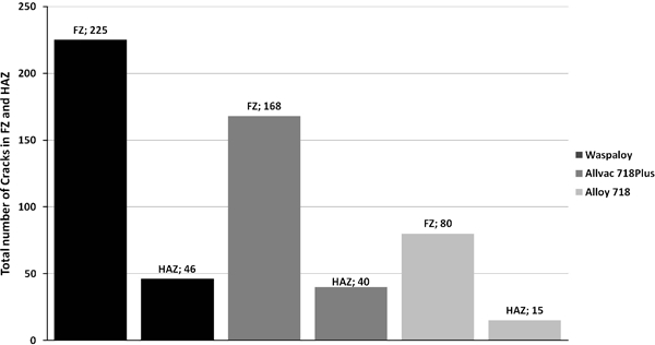
Total numbers of cracks within HAZ and FZ on Alloy 718, Allvac 718Plus and Waspaloy
Conclusions
Alloy 718 exhibits the best repair weldability followed by Allvac 718Plus and Waspaloy, as measured by the number of cracks in both HAZ and FZ.
Coarse grain materials significantly increased the susceptibility to cracking in the HAZ for all three superalloys.
A large amount of δ phase in Alloy 718 and Allvac 718Plus is not detrimental to the repair weldability.
As expected, no correlation between presolution heat treatments and FZ cracking could be advocated.
Significant hardening at the bottom layer of multiple layer welds occurred in Allvac 718Plus and Waspaloy and is associated with SAC in this part of the repair weld.
Footnotes
Acknowledgements
We sincerely acknowledge M. Pettersson, M. Karlsson, P. Karlsson, S. Frödin and L. Eriksson at Volvo Aero Corporation (VAC) for their help with the repair welding operations. B. Karlsson at VAC is highly appreciated for his help with the SEM work. We also thank Professor L.-E. Svensson at University West for the careful review of this article.