
Abstract
We examine here the spot welding characteristics of transformation induced plasticity assisted steels, which contain δ-ferrite as a consequence of their aluminium concentrations of 3·5 or 5·6 wt-% and which also have high carbon contents of 0·3 or 0·4 wt-% when compared with conventional automotive steels. The resistance spot welds are tested in both shear and cross-tensile tests in order to determine the so called ductility ratio, which is a parameter associated with the fitness of such welds for automotive applications. With an increase in the δ-ferrite fraction from 0·19 to 0·5, the hardness variation across the weld and heat affected zone is decreased approximately from 400 to 150 HV. It seems that the presence of stable δ-ferrite is helpful in reducing hardness variations and in achieving a significant ductility ratio of 0·39.
Introduction
One variant of low alloy steel that benefits from transformation induced plasticity (TRIP) contains substantial quantities of δ-ferrite, which is retained from the solidification stage and remains as a stable phase at all temperatures in the solid state.1– 3 This is unlike conventional TRIP steels,4 in which the dominant phase is allotriomorphic ferrite, but such alloys can become fully austenitic over a wide range of temperatures. 5 5,6 It follows that during rapid heat treatment of the kind associated with resistance spot welding, it is possible in conventional alloys to produce fully martensitic heat affected zones;7 it is for this reason that commercial variants are limited to carbon concentrations of ∼0·15 wt-%. A potential advantage of the δ-TRIP steel concept is that it is impossible to form completely martensitic microstructures if δ-ferrite persists at all temperatures in the solid state. The alloy concept is in its early stages of development, and although the processing and mechanical properties8 have been studied and characterised, the ability to spot weld requires detailed investigation.
Some shear tests on spot welded δ-TRIP steel in its final heat treated condition9 have indicated promise, but more detailed work to include cross-tensile tests is necessary in order to establish a parameter known as the ‘ductility ratio’, which is the ratio of the cross/shear strengths. The origin of this parameter is not clear, but a small value indicates a brittle weld. It should be noted that the limited cross-tensile tests on spot welds, as reported in Ref. 9, were on cold rolled steel rather than in the δ-TRIP condition. The purpose of the present work was therefore to undertake a more comprehensive assessment of spot welds made on δ-TRIP alloys, including new variants with compositions different from previous studies.
Alloys and experiments
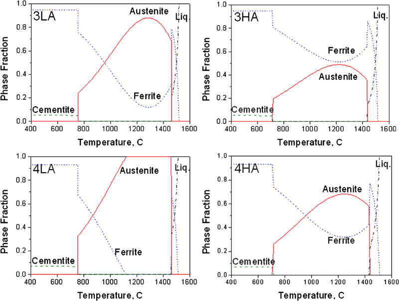
The chemical compositions of the alloys used are shown in Table 1. Variations in the carbon and aluminium concentrations are there to enable an investigation of the stability of δ-ferrite on spot weldability. Vacuum melted ingots of 25 kg were austenitised at 1200°C for 1 h followed by hot rolling to 4·5 mm in thickness with finishing rolling temperature >950°C. The hot rolled sheets were cold rolled to 1·2 mm. Figure 1 shows the equilibrium phase fractions calculated using Thermocalc software with the TCFE6 database. δ-Ferrite should persist at all temperatures after freezing, with the exception of alloy 4LA. The stability of δ-ferrite is reduced in the sequence 3HA, 4HA, 3LA and 4LA.
Equilibrium phase fractions
Chemical compositions of alloys/wt-%
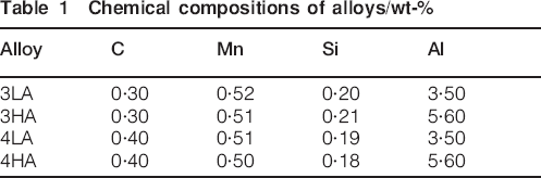
Figure 2 illustrates the microstructures obtained after hot rolling. The bands of coarse ferrite in 3HA, 4HA and 3LA alloys are ascribed to the persistence of ferrite even at hot rolling temperature. In contrast, alloy 4LA is fully austenitic at the hot rolling temperature and hence shows a uniform grain structure of allotriomorphic ferrite without any remnants of δ-ferrite.
Optical micrographs of hot rolled sheets
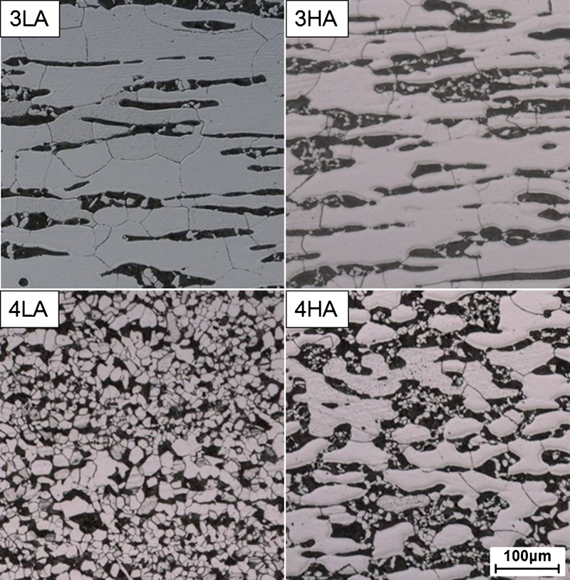
After cold rolling, samples of each alloy were intercritically annealed at 840°C for 3 min and then isothermally held in a salt bath at 400°C for 30–600 s to see the effect of isothermal holding time on the strength–elongation balance followed by air cooling to ambient temperature; the microstructures after isothermal transformation for 600 s (Fig. 3) continue to show a banded structure, especially for three alloys where δ-ferrite persists. Stabilisation of austenite is confirmed by phase mapping using electron backscattered diffraction (EBSD). For testing the mechanical properties, subsize rectangular tensile specimens were produced according to the common standard for mechanical testing of steel10 with the gauge length of 25 mm. The mechanical properties of the heat treated alloys are summarised in Fig. 4. Depending on the time period at the isothermal transformation temperature, the tensile strengths were in the range of 700–900 MPa with the total elongation between 25 and 45%, consistent with previous work.8
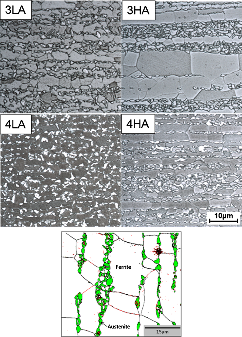
Microstructure after heat treatment (upper) and EBSD phase mapping of 4HA alloy showing retained austenite (lower)
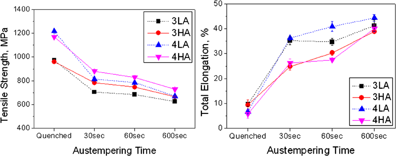
Mechanical properties of investigated alloys
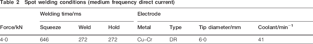
Fully heat treated specimens were spot welded under the condition shown in Table 2, according to ISO 18278. 11 11,12 The weld nuggets of specimens were sectioned in order to reveal the macro- and microstructure of the weldments. Hardness profiles were examined around weld nuggets to confirm the softening effect of δ-ferrite. Weld strength tests, which measure the tensile shear strength (TSS) and cross-tensile strength (CTS) of the welded specimen, were conducted according to Japanese Industrial Standards. 13 13,14
Spot welding conditions (medium frequency direct current)
Results and discussion
Figure 5 shows the macrostructure around the weld nugget of 3LA alloy as a function of welding current, with other details listed in Table 2. Because a higher welding current produces a larger fused volume, the size of the weld nugget naturally increases with the current. The weld strength is in turn related to the nugget size15– 17 so that a greater current leads to a stronger weld, but a limiting condition is reached when instabilities arise, and the material is expelled in liquid form.18 Figure 6 shows the change in nugget size with current. Imin represents the current required to obtain a minimum nugget size equal to 4t1/2 (where t is thickness of the sheet), corresponding to the fusion zone size required for strong steels in order to avoid the interfacial failure mode. 15 15,19 Imax is that at which expulsion starts to occur. It is found that the allowable current ranges (Imax–Imin) of all the investigated alloys exceeded 1 kA, which is considered to be important in practical applications.
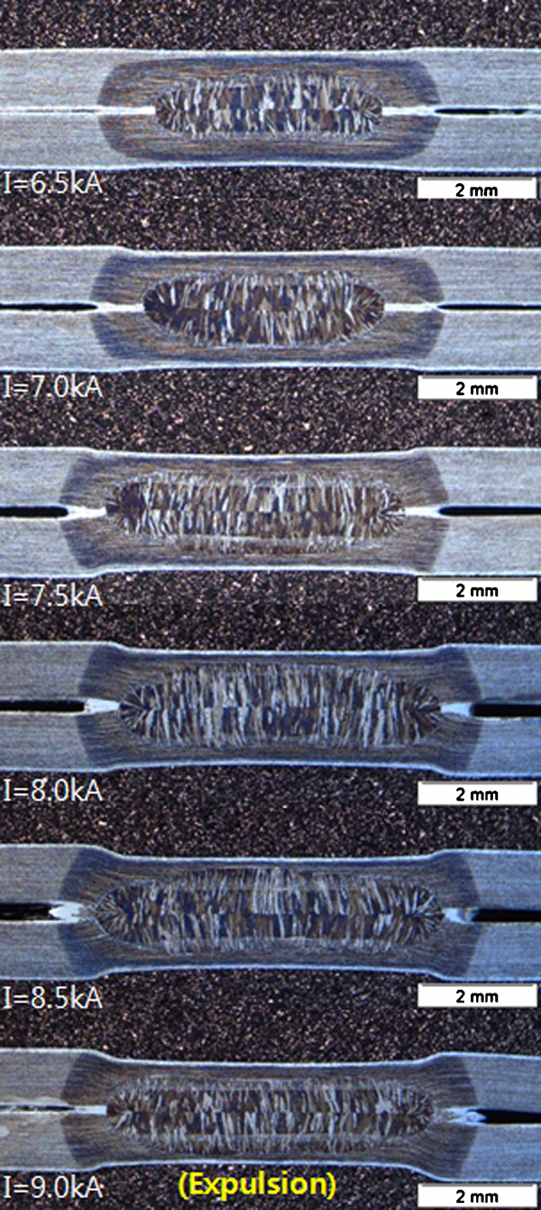
Change in weld nugget size with weld current (3LA alloy)
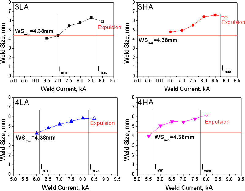
Suitable current ranges for spot welding
The microstructures of the weld nuggets are given in Fig. 7 for cases where the current was 0·5 kA less than Imax. Owing to the high aluminium concentrations of the steels used, δ-ferrite with dendrite morphology remains in the fusion zone even in the 4LA alloy, where δ-ferrite is not expected as an equilibrium phase at ambient temperature, but not surprising given the high cooling rates associated with spot welding. The volume fractions of δ-ferrite in the weld nuggets were measured with a point counting method and are listed in Table 3. Alloy 3HA has the largest fraction of δ-ferrite, consistent with the equilibrium diagrams in Fig. 1, and the others are roughly consistent with the expectations given that the microstructures have not been generated under equilibrium conditions.
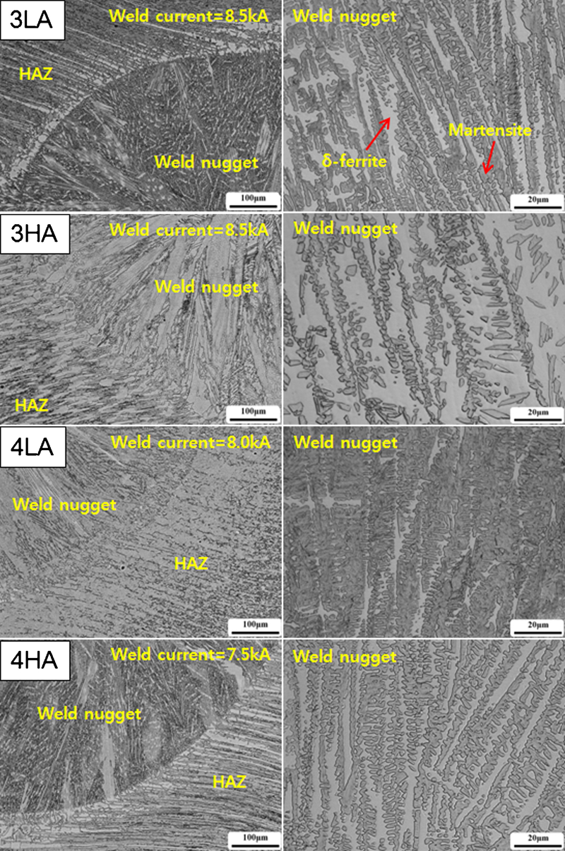
Optical micrographs around fusion zones
δ-Ferrite volume fraction in weld nugget
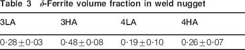
The softer δ-ferrite in the weld nuggets is expected to mitigate any brittleness, both of the weld nugget and in the heat affected zone. Figure 8 shows the hardness profiles that start in the nugget and then traverse into the base metal, as shown in Fig. 9. The hardness difference between the nugget and the base metal is gradually reduced as the fraction of δ-ferrite in the weld nugget increases. The hardness of the fusion zone in the 4LA alloy is three times higher than that of the base metal, but the difference decreases to 1·5 times in 3HA alloy rich in δ-ferrite; this should result in better mechanical properties.
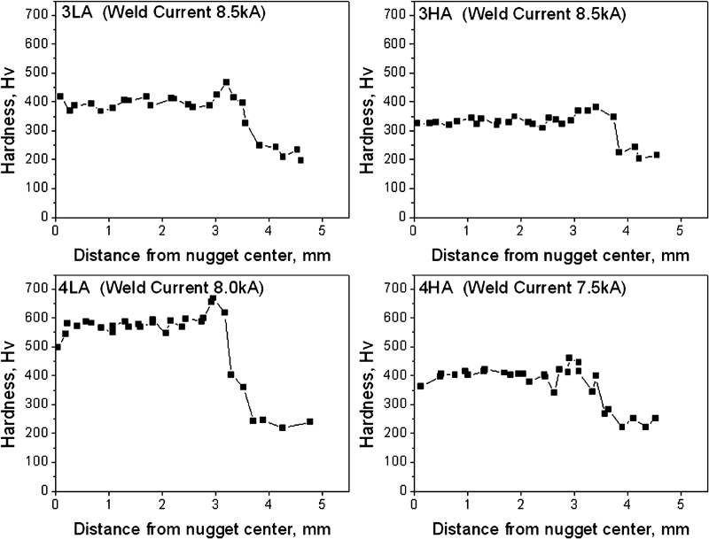
Hardness profiles of fusion zone and base metal
Hardness measurement across weld nugget
Figure 10 compares the strength of welds in alloys 3LA and 4LA with their different δ-ferrite fractions. The TSS and CTS data are determined using standard methods. 13 13,14 The two measures of strength increased in both steels with the nugget size, as is already known.17 However, it is noteworthy that alloy 3LA shows a more prominent improvement in CTS with nugget size. Even though the microstructural parameters that govern these measures of strength are not clearly understood, it has been reported for conventional steels that the shear strength scales with that of the base metal, but the CTS tends to deteriorate when the carbon equivalent exceeds 0·24 wt-%.16 A deterioration in the CTS could therefore be interpreted as the onset of brittleness, and an empirical parameter, the ratio of the cross/shear strength, which is referred to as the ductility ratio, is used to indicate weld ductility.20 Figure 10 shows that the ductility ratio for alloy 3LA is greater than that for 4LA primarily because of the improved CTS in the former cases. There are two factors that contribute to the better properties of alloy 3LA, the lower carbon equivalent and the greater stability of δ-ferrite in the material. It is likely that the latter factor is of greater influence, given the more uniform distribution of hardness across the weld.
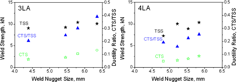
Mechanical response of weld joint as TSS, CTS and ductility ratio (CTS/TSS) (▪: interfacial fracture; ★: partial plug fracture; •: plug fracture)
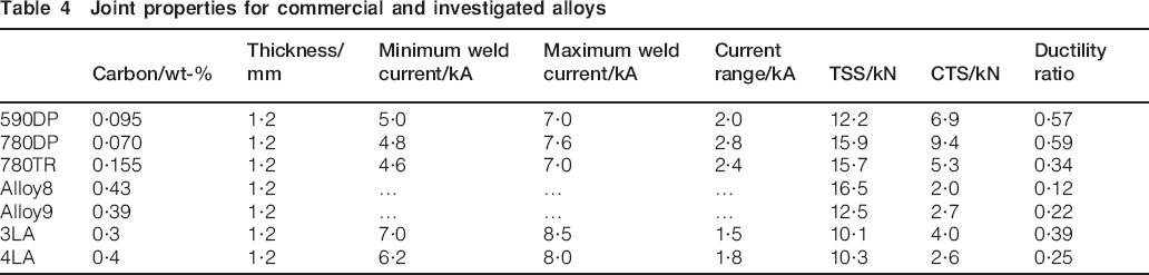
Comparisons of the performance of the current alloys against commercial high strength low alloy steels21 are made in Table 4, including data from previous work.9 The ductility ratio of 3LA exceeds that of commercially available 780TRIP steel in spite of its higher carbon content. This supports the hypothesis that the presence of δ-ferrite is advantageous in enhancing the spot weldability even when the carbon equivalent exceeds 0·24 wt-%.
Joint properties for commercial and investigated alloys
Conclusions
The microstructure and mechanical response of resistance spot welds in recently developed δ-TRIP steel containing 0·3 or 0·4 wt-% carbon and 3·5 or 5·6 wt-% aluminium have been characterised, leading to the following conclusions.
The retention of δ-ferrite within the weld nugget is the greatest in alloys where the calculated equilibrium phase diagram indicates a high stability for the phase.
The increase in δ-ferrite fraction from 0·19 to 0·5 in the fusion zone reduces the difference in hardness between the fusion zone and the base metal approximately from 600 to 150 HV. This contributes to improving the ‘ductility’ of the welded joints as defined by the ratio of CTS/TSS.
Footnotes
Acknowledgements
The authors acknowledge Professor N. J. Kim for the provision of laboratory facilities at GIFT and support from POSCO through the Steel Innovation Programme. The authors are also grateful for the support from the World Class University Programme of the National Research Foundation of Korea, Ministry of Education, Science and Technology, under project no. R32-2008-000-10147-0.