
Abstract
Dissimilar lap joints of aluminium and stainless steel were first friction stir welded by the tool with a cutting pin. The results showed that sound joints could be obtained by this method. When the pin was inserted into the lower steel sheet, macrointerlocks were formed by the steel flashes plugging into the upper aluminium at both sides of the nugget bottom. At the aluminium/steel interface, a thin intermetallic compound (IMC) layer and the mechanical bonding of microinterlocks were formed. In addition, the aluminium near the interface was also strengthened by grain refinement and IMC particles. Therefore, the beneficial effect of the macrointerlocks provided by the steel flashes was removed, the shear strength of the joint reached 89·7 MPa, which was even higher than that of the base metal of aluminium.
Introduction
Friction stir welding (FSW), a solid state joining process developed by The Welding Institute in 1991,1 has two significant advantages. One is the lower welding temperature compared with conventional fusion welding methods; the other is the higher efficiency or versatility compared with conventional solid joining methods. Because its low temperature and short time are beneficial for suppressing metallurgical reaction, FSW becomes a promising technique for joining dissimilar alloys tending to form intermetallic compounds (IMCs), such as aluminium/steel,2– 12 aluminium/copper13 and titanium/steel.14 Moreover, due to its versatility, FSW is used for various joint configurations ranging from butt to lap and spot weld joints.
In the field of dissimilar alloy FSW, the joining of aluminium alloy to stainless steel has been intensively studied to meet the growing demand,2– 12 and several important results were obtained by using different joint configurations. It is now well known that inserting the pin into the softer aluminium near the joining interface can avoid the wear of pin and the overheating of aluminium, 3 3,4 while the joint strength is lower, due to the formation of brittle IMCs are usually presented at the joining interface between aluminium and steel.3– 5 On the other hand, the joint strength can be enhanced by plunging part of the pin into the steel; however, if the offset (for butt joint) or depth (for lap and spot joints) into steel is too large, the pin wears out in a shorter time with the aluminium oxidised or burned,10 and many voids are introduced into the joint by the strain mismatch15 (or named discontinuous flow)16 between aluminium and steel. Therefore, strict control of the offset or depth of the pin into steel is considered as a necessary prerequisite for producing a sound joint, and the suitable values of depth should be 0·2–0·3 mm10 for the butt joint and 0·1 mm for the lap joint. 9 9,11 Nevertheless, this severe restriction on pin location increases the difficulty of aluminium/steel FSW, especially for the lap joint, because how much the pin is inserted into the lower steel of the lap joint cannot be observed directly. Furthermore, it is also difficult to hold the preset shallow insertion (∼0·1 mm) during the welding process, because it is hard to prevent the pin tip inserted into steel from slight wear.
In order to solve the dilemma the pin insertion should not be too shallow or too deep during the friction stir lap welding (FSLW) of aluminium to steel, Chen et al. 6 6,9 adopted a zinc coat steel and kept the pin in the aluminium; they found that the zinc coating improved the weldability between aluminium and steel. Another suggested approach was to select a hard tool such as Polycrystalline Cubic Boron Nitride nitride for deep insertion joining, and then the pin could resist the wear when it was plunged into the lower steel deeply.9 However, the prerequisite of the zinc coating complicated the joining process, and the hard tool cannot solve the problems of the overheating of aluminium and the strain mismatch between aluminium and steel.
In this study, a pin with cutting edges was used for the FSLW of aluminium to steel. Pins with threads or flutes have already been widely used in FSW, the aim of which is to increase the friction area and the effect of stir.17 The goals of this study are to research whether the aluminium/steel lap joint could be welded by a cutting pin when it was inserted into the lower steel and whether high welding temperature and strain mismatch could be reduced by the cutting pin. The temperature of the joining process was measured. The structure and composition of the joining interface were examined, and the joint strengths were evaluated by shear tests.
Experimental procedure
The base materials used in the experiment were 2·2 mm thick 1100 aluminium alloy and 1·1 mm thick 1Cr18Ni9Ti stainless steel sheets, and the sheets were machined into rectangular specimens of 120×280 mm dimension. The welding tool was fabricated by an H13 steel holder and a pin of YG8 rotary burrs, as shown in Fig. 1a. The chemical compositions of the base materials, the holder and the pin are shown in Table 1. The diameter of the tool shoulder was 25 mm and that of the pin was 6 mm. The cutting pin of the rotary burrs has a flat end face and 15 spiral cutting edges, as shown in Fig. 1b and c.
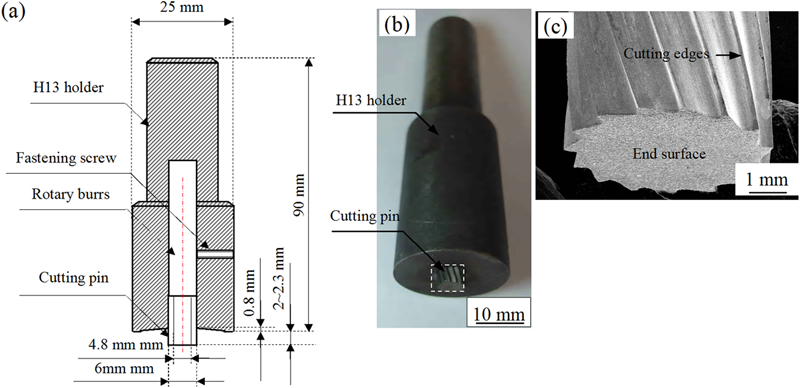
Structure of welding tool
Chemical compositions of base materials and tool
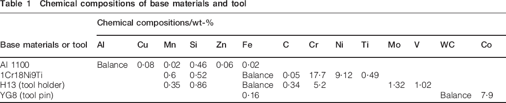
Before welding, the aluminium sheet was put on the steel sheet in a lap joint configuration, as shown in Fig. 2. During welding, the tilt angle and rotation rate of the tool were 0° and 950 rev min−1 respectively, the welding speed varied from 60–375 mm min−1. Two lengths of the cutting pin, 2 and 2·4 mm, were employed during the FSLW to investigate whether the cutting pin could reinforce the joining by increasing the pin insertion. To analyse the effects of the cutting pin, two kinds of pins were used during the FSLW with deeper insertion of 2·4 mm: one was the cutting pin, and the other was a smooth cylinder pin without the cutting edges, which was also made of YG8 steel and had the same diameter (6 mm) and length (2·4 mm) as the former. The temperature was measured by a thermocouple placed at a point in the steel, the relative position of which (point A) and the joint are shown in Fig. 2.
Schematic illustrations showing structure of lap joint and relative position of joint and thermocouple
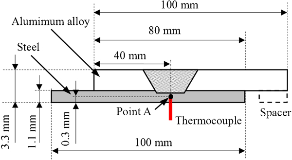
The structure and composition of joining interface were detected by SEM (JEOL, JSM-6700) equipped with an energy dispersive spectroscopy (EDS). The joint strength was evaluated by tensile shear tests (Instron 5880). The test specimens were cut along the welding direction, during which the centreline of the specimens coincided with that of the joint, and two notches were carefully cut out on the welded aluminium and steel sheets respectively to ensure that the shear load was entirely applied on the joining interface, as shown in Fig. 3. The tests were performed at a crosshead speed of 1 mm min−1, and then the fracture surfaces of the joints were analysed by SEM.
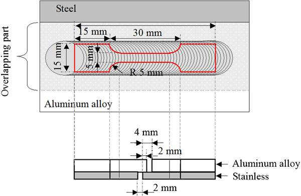
Schematic illustrations showing relative position of shear test specimen and lap joint and structure of shear test specimen
Results and discussion
Figure 4a shows a typical cross-section of the joint produced by the cutting pin with the short insertion of 2 mm. During the welding process, the pin was entirely inserted into the aluminium but not contacted with the lower steel. The straight joining interface shown in Fig. 4 indicates that the steel was hard enough to resist the possible deformation induced by the aluminium plastic flow. The microstructure of the joining interface is shown in Fig. 4b. An IMC layer (∼2 μm thickness) is present at the straight interface; the composition of point B in Fig. 4b is 78Al–22Fe (at-%). Thus, it is reasonable to speculate that the IMC is Al3Fe.18
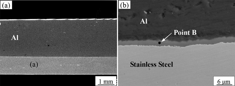
Typical structures of joining interface produced by short insertion FSLW
When deeper insertion (2·4 mm insertion) FSLW was performed by the smooth pin, the pin was broken in such a short time that one complete joint could not be obtained no matter what welding speed was used. Figure 5 shows the welded part of the joint that was fabricated at a welding speed of 95 mm min−1. It can be found that the steel flashes plugged into the upper aluminium at the both sides of the nugget bottom, which was probably due to the cutting action provided by the sharp edge of the end face of the smooth pin. The second feature shown in Fig. 5 is that the irregular steel scraps were embedded in the upper aluminium, which is the cutoff steel broken by the aluminium plastic flow. Finally, it can be found that a thick layer of steel plastic flow (∼0·5 mm) was formed by the stir of the pin. However, the flow is discontinuous because the layer structure and voids are clearly presented in it. The thick layer of steel plastic flow indicates that the smooth pin has inputted much heat into the joint. This was probably caused by the fact that the pin inserted into the hard steel had difficulty travelling along the welding direction, and then a large friction force and much friction heat had been produced between the pin and the base materials to soften the steel and produce steel plastic flow, which could accommodate the travel of the pin. However, the friction force was so large that the smooth pin was broken soon after being plunged in the specimens, it was not enough for producing a continuous steel flow.
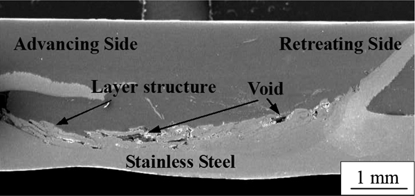
Cross-sectional macroimages of welded part of joint fabricated under conditions of smooth pin without cutting edges, deep insertion (2·4 mm) and 95 mm min−1 welding speed
The cutting pin exhibited good wear resistance during deep insertion welding. Figure 6 shows the appearance of the cutting pin, which has welded 40 joints (their length amounted to 8 m) with deep insertion. It can be observed that the pin does not shorten at all, and the cutting edges are retained, although some aluminium sticks to the pin surface.
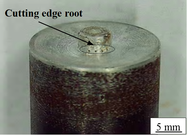
Appearance of cutting pin, which had welded 40 joints with deep insertion
The macromorphologies of the joining interfaces forming the deeper insertion (2·4 mm insertion) FSLW with the cutting pin are shown in Fig. 7. The steel flashes and scraps can be also found in the upper aluminium. However, compared with Fig. 5, the aluminium/steel interface in Fig. 7 is flat at the nugget bottom, and no thick stirred layer can be found in the steel, which reveals that, although the pin was indented into the lower steel sheet during welding, the hard steel could be easily removed by the cutting pin. Therefore, the cutting edges of the pin played an important role in material transfer, and the heat input by the cutting pin was much less than that input by the smooth pin. This speculation is supported by the measured temperature. Figure 8 shows the temperature of the position in the steel and near the end face of the pins (point A in Fig. 2) during the welding performed by the cutting or the smooth pin at a welding speed of 95 mm min−1. It can be found the maximum value of the former was only 351°C, while that of the latter reached 419°C. That the temperature during the cutting pin welding was not too low indicated that the material transfer was not only carried by the cutting of the edges but also by the friction between the pin and the base materials, so the sticking aluminium was found on the pin (Fig. 6).
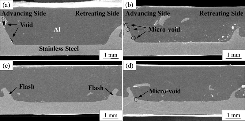
Cross-sectional macroimages of joints produced by deep insertion FSLW at welding speeds of a 95 mm min−1, b 150 mm min−1, c 230 mm min−1 and d 375 mm min−1
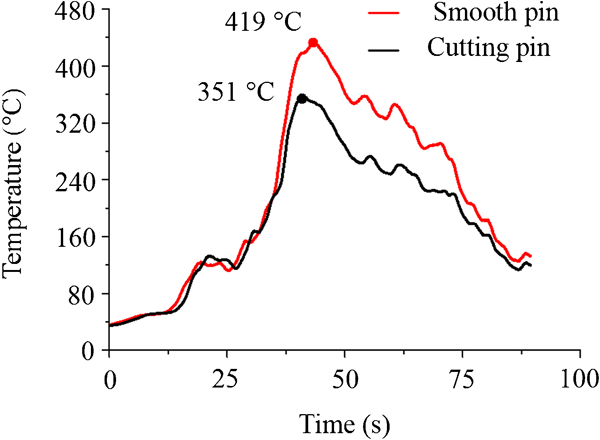
Temperatures of point A in steel (Fig. 2) when aluminium/steel was welded respectively by smooth pin without cutting edges and cutting pin at welding speed of 95 mm min−1
Figure 7 also indicates that the thickness of the steel flash or cutoff layer slightly decreases with increasing welding speed, which may have resulted from the inversely proportional relationship between the energy or heat inputted per length and the welding speed.19 Therefore, the cutting pin softened or peeled off less steel at a higher welding speed. The other characteristic shown in Fig. 7 is that the voids are located near the flash at the advancing side (Fig. 7a, b and d). The voids resulted from the insufficiency of plastic flow. It has been well known that during FSW or FSLW, the material intersecting the pin is dragged around the retreating side and deposited on the advancing side.20 Therefore, if the plastic flow is insufficient, voids will be found at the advancing side, where the final position is reached by the flow. During the cutting pin welding with deep insertion, more steel was softened or peeled off by the pins at the slower welding speed (Fig. 7a and b), then more space is left behind it. On the other side, when the welding speed was too high (Fig. 7d), the aluminium flow had no enough time to fill the space left by the cutting pin. Both situations could make the plastic flow relatively insufficient.
Since a steel layer was peeled off during the FSLW performed by deep insertion of the cutting pin, the fresh steel contacted with the aluminium plastic flow, which led to strong mechanical and metallurgical interactions at the aluminium/steel interface. The typical microstructure of the interface located at the nugget bottom of joins is presented in Fig. 9a. In addition to a thinner IMC layer (∼1 μm) presented at the interface, a mixed layer of 15–20 μm is also found in the steel side, which shows a stripe-like structure constituted by darker and lighter slices. In some regions, the mixed layer becomes thicker (about 20–30 μm) with a vortex-like structure, as shown in Fig. 9b. The EDS analysis of the IMC layer (point C in Fig. 9b) indicates that the Al/Fe ratio is 77∶23 (at-%), so the IMC is Al3Fe, which is the same as the IMC shown in Fig. 4b, while the Al/Fe ratio in the darker slices (point D in Fig. 9b) of 82∶18 (at-%) may be Al4Fe, as proposed by Lee et al.21 The lighter slices (point E in Fig. 4b) are mainly composed of Fe, Cr and Ni, while Al is only ∼0·8 (at-%); therefore, it can be deduced that they are the solid solution of Al in steel.
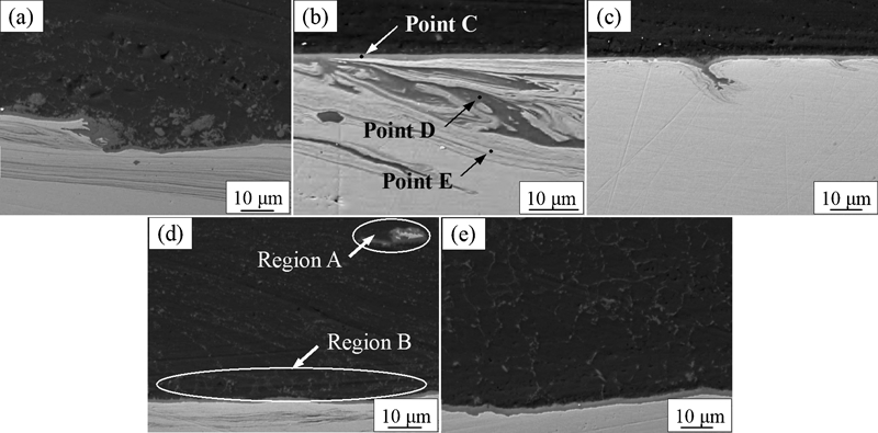
Microstructures of joining interface formed by deep insertion of cutting pin
The mixed layer was induced by the strain mismatch between aluminium and steel, i.e. they have different plastic deformabilities. During FSLW performed by deep insertion of the cutting pin, some aluminium was brought under the end face of the rotating pin and underwent severe deformation with a thin layer of steel. Nevertheless, because of the strain mismatch between aluminium and steel at the welding temperature, steel had a lower ductility compared to aluminium; thus, the microcracks tended to form in the steel side, which made it possible for the aluminium flow to squeeze into these cracks and then reacted with steel. Consequently, some microinterlocks were generated at the interface, as shown in Fig. 9c. With more microinterlocks being created and stretched, the mixed layer of stripe-like structure was formed (Fig. 9a), and it could even develop into a vortex-like structure (Fig. 9b). Since the aluminium/steel reaction experienced shorter time in the cracks than that at the interface, the non-equilibrium phase of Al4Fe was formed in the cracks (point D in Fig. 9b).
It can be found from Fig. 9a that the IMC at the interface is broken into particles, which are distributed in the aluminium side near the interface. Region A shown in Fig. 9d reveals that the steel scrap embedded in aluminium is another source of IMC particles. During the welding, the steel scraps were continuously broken and reacted with aluminium; then, many IMC particles were produced. The IMC particles in Fig. 9 present two distribution patterns. First, the IMC particles are distributed along the boundaries of the elongated aluminium grains and thus exhibit a streamline pattern, as shown in Fig. 9d. Second, in the region adjacent to the interface (region B in Fig. 9d) or the central part of the nugget bottom (Fig. 9e), the IMC particles are distributed on the boundaries of fine equiaxed grains, which demonstrates that these regions were subjected to more severe deformation and higher temperature, and then the elongated grains were transformed into fine equiaxed grains by the dynamic recrystallisation process of FSLW.
Since the smooth pin could not produce one complete joint, its strength was not measured. The shear strengths of the joints fabricated by the cutting pin are shown in Fig. 10. The strengths of the joints welded by the short insertion are significantly lower than those welded by the deep insertion.
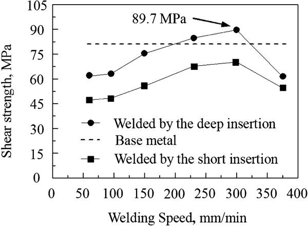
Shear strengths of joints produced by cutting pin with short and deep insertions at various welding speeds
During the shear test, the short insertion joints were all fractured at the welding interface. Figure 11a shows the fracture surface of the joint (the steel side) produced at the welding speed of 300 mm min−1. Some regions of the surface are covered by a thin aluminium layer, and the flat region, detected by EDS analysis, is covered by the IMC. From this phenomenon and the straight and brittle IMC layer shown in Fig. 4b, it can be concluded that the joining interface was the weakest region in the short insertion joints. Since the deep insertion joints were strengthened by microinterlocks (Fig. 9a–c) between steel and aluminium, these joints were ruptured in the aluminium side during the shear test. Furthermore, since the aluminium near the interface was reinforced by fine aluminium grains and the IMC particles (Fig. 9d and e), the shear strength of the deep insertion joint reaches 89·7 MPa at a welding speed of 300 mm min−1 (Fig. 10), which is even higher than that of the base metal of aluminium (81 MPa). The fracture surface of the joint (the steel side) is shown in Fig. 11b. The surface is covered by a thick aluminium layer and exhibits a classical ductile failure with the morphology features of microscopic cracks, tear ridges and shallow dimples. Figure 10 also indicates that the joint strength decreased when the welding speed was lower or higher than 300 mm min−1. It possibly resulted from the fact that these joints had some macro- or microvoids, which impaired the joint strengths.
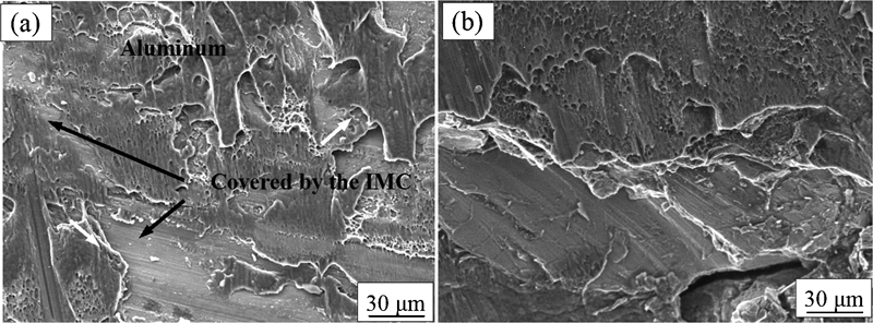
Fracture surface morphologies of joints fabricated by cutting pin
It should be pointed out that the high strength of the joint welded by deep insertion of the cutting pin did not result from the mechanical bonding, which was formed by the macrointerlocks of the steel flashes between aluminium and steel (Fig. 7). Because the shear test specimens were prepared by cutting the joint along the welding direction (Fig. 3), the shear load was also parallel to the welding direction. Therefore, the high strength was mainly attributed to the thinner IMC layer and the mechanical bonding of the microinterlocks at the aluminium/steel interface (Fig. 8).
Conclusions
The lap joints of aluminium and stainless steel have been welded by the smooth cylinder pin and the cutting pin respectively. The main results are as follows.
When the lad joint was welded by the cutting pin with the insertion less than the thickness of the upper aluminium (2·2 mm), i.e. the short insertion of 2 mm, an IMC layer was formed at the straight joining interface.
When both kinds of pins were plunged into the lower steel with deep insertion of 2·4 mm, the smooth pin was broken soon after being plunged into the joint, while the cutting pin exhibited good wear resistance during the joining. Moreover, the temperature in the steel and near the pin reached 419°C during the smooth pin welding, while it reached 351°C during the cutting pin welding.
In the joint welded by the smooth pin with the deep insertion, a thick stirred layer that presented a discontinuous flow was found in the steel. In the joint welded by the deep insertion cutting pin, the flat interface at the nugget bottom and the not too low welding temperature indicated that the material transfer was carried by the edge cutting and the friction between the pin and the base materials.
A thinner IMC layer and microinterlocks were produced at the joining interface of the joint welded by the cutting pin with deep insertion. The highest shear strength of the joint reached 89·7 MPa, which was even higher than that of the base metal of aluminium.
Footnotes
Acknowledgements
This work was financially supported by the National Natural Science Foundation of China (grant no. 51071123) and the fund of the State Key Laboratory of Solidification Processing in NWPU (grant nos. 43-QP-2009 and 31-TP-2009).