
Abstract
Dissimilar spot welds of magnesium–aluminium alloy were produced via a solid state welding process, i.e. ultrasonic spot welding, and a sound joint was obtained under most of the welding conditions. It was observed that a layer of intermetallic compound (IMC) consisting of Al12M17 formed at the weld centre where the hardness became higher. The lap shear strength and failure energy of the welds first increased and then decreased with increasing welding energy, with the maximum lap shear strength and failure energy occurring at ∼1250 J. This was a consequence of the competition between the increasing diffusion bonding arising from higher temperatures and the deterioration effect of the intermetallic layer of increasing thicknesses. Failure predominantly occurred in between the aluminium alloy and the intermetallic layer, which normally stayed at the magnesium side or from the cracks of the IMCs in the reaction layer.
Introduction
Magnesium and aluminium alloys, which offer high strength, good formability and weight savings, are being considered for the fabrication of vehicles in order to reduce the effect of green house gas emissions.1– 5 In order to achieve a combination of the properties of Mg and Al alloys, development of reliable joints between Mg and Al alloys is required. Fusion welding of Mg and Al alloys always produces coarse grains and large brittle intermetallic compounds (IMCs) in the weld metal. This situation suggests that fusion welding of Mg and Al alloys cannot be practically used. According to Rathod and Kutsuna,6 in case of dissimilar joints such as steel/aluminium and titanium/aluminium alloys, it is easy to realise solid/liquid state reaction at the joining interface between two metals, where only the metal with lower melting temperature is melted. However, it is difficult to apply this method to Mg–Al alloy joint due to the small difference between their melting points. Therefore, another approach to control IMC formation has to be developed for joining Mg and Al alloys.
Ultrasonic spot welding (USW) of metals 7 7,8 is a solid state process that produces coalescence through the simultaneous application of localised high frequency vibratory energy and moderate clamping forces. It is more effective than resistance spot welding (RSW), using only 0·6–1·5 kJ of energy per weld. Energy is usually generated at the weld line in USW9 rather than on the top surface as in friction stir spot welding.
A number of papers have recently reported on the joining of dissimilar alloys by friction stir welding, friction stir spot welding, laser welding and RSW especially for Mg and Al alloys.2– 4,10–14 However, very little work has been reported for joining of Mg and Al using USW. While joining Mg and Al alloys, the main disadvantage is the formation of brittle IMCs, and it is well known that the mechanical properties of the joints are closely related to the morphology and distribution of the intermediate layer of the joint.15 The aim of this research is to better understand the nature of the problem in dissimilar USW of AZ31-H24/Al5754-O.
Experimental
A commercial 2 mm thick AZ31-H24 Mg alloy and 1·5 mm thick Al5754-O Al alloy sheets provided by General Motors Company were used for USW. The chemical composition of the AZ31-H24 samples was Mg–3Al–1Zn–0·6Mn–0·005Ni–0·005Fe and that of the Al5754-O samples was Al–3·42Mg–0·63Mn–0·23Sc–0·22Zr. The HP-USW system employed was a dual wedge reed, Sonobond-MH2016 machine. The specimens were 80 mm long and 15 mm wide. The faying surfaces of the specimen were ground using 120 emery papers and then washed using acetone and dried before welding. The samples were welded at energy inputs from 250 to 3000 J at a constant power setting of 2000 W, an impedance setting of 8 on the machine and a pressure of 0·414 MPa. Four samples were welded for each welding condition; two of them were used for microstructure and microhardness and the other two for lap shear test. Cross-section samples were examined using scanning electron microscopy (SEM) and X-ray diffraction (XRD) techniques. Mounted samples were polished using diamond paste and MasterPrep. A computerised Buehler microhardness testing machine was used for the microindentation hardness tests diagonally across the welded joint samples using a load of 100 g for 15 s. In order to evaluate the mechanical strength of the joints and establish the optimum welding conditions, tensile shear tests of the welds were conducted to measure the lap shear failure load using a fully computerised universal testing machine with a constant displacement rate of 1 mm min−1 in air at room temperature. The samples were loaded along the length direction of the joined coupon pairs. In tensile shear testing, restraining shims were used to minimise the rotation of the joints and maintain the shear loading as long as possible.
Results and discussion
Microstructural evolution
Microstructural characterisation was conducted across the welding line of the samples. Figure 1a and b depicts the typical microstructure of the welded sample of AZ31 and Al5754 at 1500 and 3000 J energy inputs respectively. The weld had no large defects, such as crack or tunnel type defects. A sound joint was obtained under most of the welding conditions, but a crack was observed on the weld surface at energy inputs of 2500 J and above. This crack was thought to be related to the frictional heat generated between the welding tip (made of steel) and the welded sheets and the restraint between them leading to tensile residual stresses in the sheet. It can be seen from Fig. 1a that there is an IMC layer between the two alloys, which is distributed heterogeneously. This may be because the temperature distribution is not homogeneous across the welding line owing to the short initial welding time. In the 500 J energy input sample, discontinuous layers of IMC have been found, while in the 3000 J energy input sample, continuous layers of IMC have been observed owing to the equal distribution of the temperature at higher energy input (Fig. 1b). High local temperatures and strain rate and pressure promote chemical reaction and accelerate diffusion, leading to metallic bonding between the two sheets.16 The chemical reaction and diffusion between the Mg and Al alloy result in the formation of the IMC layer. Oxide films will first break down locally at asperities on the contacting surfaces and will allow interdiffusion of Mg and Al to occur. If the kinetics is sufficiently rapid, it creates the simultaneous formation of the IMC layer. Several previous works on the mechanical properties of dissimilar welds have suggested that the weld strength is affected by the thickness of the IMC layer formed at the interface. On examination of the cross-sections of the Mg–Al welds, the IMC layer was clearly visible at the joint interface even after very short welding times. Figure 1c shows that at low welding energy input (500 J), a discontinuous IMC layer with a maximum thickness of 2 μm was already present. With higher weld energy input (3000 J), the thickness of the IMC layer increased to 25 μm.
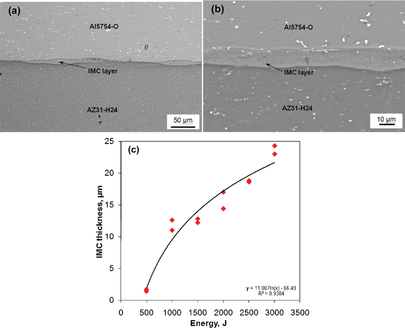
Microstructures of AZ31 and Al5754 welded samples at a 1500 J and b 3000 J energy inputs and c relation between IMC thickness and different energy inputs
To identify the IMC phase in the interface layer formed between the Mg and Al alloy during the USW, energy dispersive spectroscopy (EDS) has been conducted at the centre of the cross-section and on the fracture surface of the weld on the 1500 J energy input samples. Figure 2a shows the area analysis of the fracture surface (Mg side). The EDS results showed that 58·7 at-%Mg and 41·3 at-%Al were present, which indicates that the reaction interlayer is mainly comprised of a single IMC of Al12Mg17. Similar EDS area analysis on the fracture surface of the Al side was also performed. However, IMCs of Al12Mg17 have not been found, which indicated that the failure predominantly occurred in between the aluminium alloy and the intermetallic layer, which normally stayed at the magnesium side or from the cracks of the IMCs in the reaction layer. The present dissimilar USW is likely exposed to peak temperatures above 460°C as confirmed by thermocouple measurements at the centre of the weld of similar Mg alloy.17 This peak temperature is sufficient for mutual diffusion between Mg and Al. Even though USW is a solid state joining process, in dissimilar USW, it may be possible that constitutional liquation occurs due to the high frequency vibration and resulting heating. After constitutional liquation, the liquid phase solidifies during the cooling cycle of USW. In the binary Al–Mg system, there are two low melting point eutectic reactions:18 one between the Mg solid solution and Al12Mg17 at 437°C and the other between Al and Al12Mg17 at 460°C. This clearly indicates that Al12Mg17 is formed first by solid state reaction on the Mg side at 437°C, and then it creates an interface layer, which penetrates along grain boundaries into the Mg sheets to resolidify as Al12Mg17 and Mg eutectic structure. A second interlayer is also visible in Fig. 2b on the Al side of the Al12Mg17 layer. This layer has not yet been identified but may be indicative of the formation of Al3Mg2. This phase has also been reported in the literature.1 Thus, the results of SEM, EDS and Al–Mg phase diagram all suggest that the non-uniform IMC layer has a solidified microstructure experiencing the eutectic reaction, liquid→Al12Mg17+Mg, after the primary solidification of Al12Mg17. The EDS line analysis across the interface in a 3000 J energy welded sample is shown in Fig. 2b. Both Mg and Al are present in fairly constant concentrations across the entire IMC layer. This also indicates the Al12Mg17 phase.
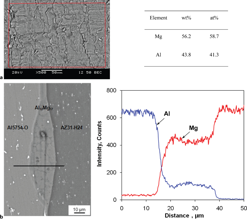
Energy dispersive spectroscopy analysis
For further separate verification of IMCs, the fracture surface of the Mg side of the welded sample was analysed by XRD. Figure 3 shows large peaks of Mg and small peaks of IMC Al12Mg17. These IMCs were considered to form by the interdiffusion behaviour of Mg and Al atoms during USW. The XRD spectrum confirms that the non-uniform IMC layer of the dissimilar weld contains a large volume of the IMC Al12Mg17. Similar results were also reported in the literature.1,3– 5,11,12 Kostka et al. have confirmed the presence of other phase Al3Mg2 in friction stir welding using a transmission electron microscope.16 However, the XRD technique cannot detect the presence of very minor phases, if present.
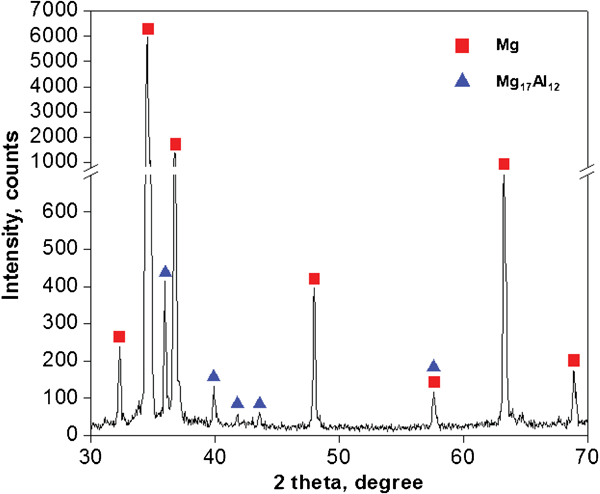
X-ray diffraction on fracture surface of 1500 J energy input welded sample
Mechanical properties
Unlike RSW, USW displays no clearly discernible fusion or heat affected zone that can degrade the strength of the metals being joined. 7 7,8 It can be inferred that in USW, the heat affected zone is small because of the poor conductivity of the welding tip (steel) compared to the thermal conductivity of the samples. The hardness profile across the non-uniform IMC layer, which was measured along the diagonal line, is shown in Fig. 4. It can be seen that hardness decreases with increasing energy input, owing to the increasing grain size at higher temperature. The non-uniform IMC layer at the weld centre has hardness values between 200 and 300 HV. This higher hardness is due to the brittle IMCs of Al12Mg17 present at the centre of the weld. Similar results were obtained by other researchers. 1 4 5 14 1,4,5,14,19 Therefore, the hardness test also verified the presence of hard IMCs. Thus, USW of the Mg and Al alloys produces a brittle interfacial layer composed mainly of IMCs, which provide an easy fracture path.
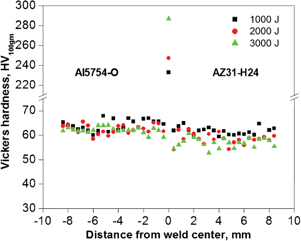
Microhardness profile in welded joints at different energy inputs
The results of the lap shear tensile tests of the Mg and Al alloy weld joint are shown in Fig. 5a. The maximum lap shear strength was ∼36 MPa at 1250 J energy input (based on the maximum lap shear fracture load divided by the nugget area 8×6 mm), which is lower than the lap shear strengths (assumed as half of the tensile strength) of the AZ31-H24 and Al5754-O base metals, which are 135 and 145·5 MPa respectively. 20 20,21 With increasing energy input, the lap shear strength was increased in the beginning owing to high temperatures and strain rate, which accelerate diffusion in between the Mg and Al alloy, but at very high energy inputs, it was decreased. It seems that the decrease in lap shear strength is related with the thickness and presence of cracks in the reaction layer. Therefore, as the thickness of the brittle IMC layer increases, the lap shear strength decreases. Figure 5b shows the relationship between the average value of the failure energy (as determined by integration of the lap shear fracture load curves) and the welding energy input. It can be seen that at the beginning, failure energy increases with the energy input and reaches a maximum ∼1·14 kN mm, and then it decreases due to the larger brittle IMC layer. From these results, it was assumed that the thickness of the IMC was closely related to the strength of the Mg–Al USW joint. In Fig. 2a, the fracture surface appeared coarse and dark grey. The fracture surfaces on the Mg alloy consisted of protuberances and cleavage cracks, which were considered as proof of the brittle fracture mode.
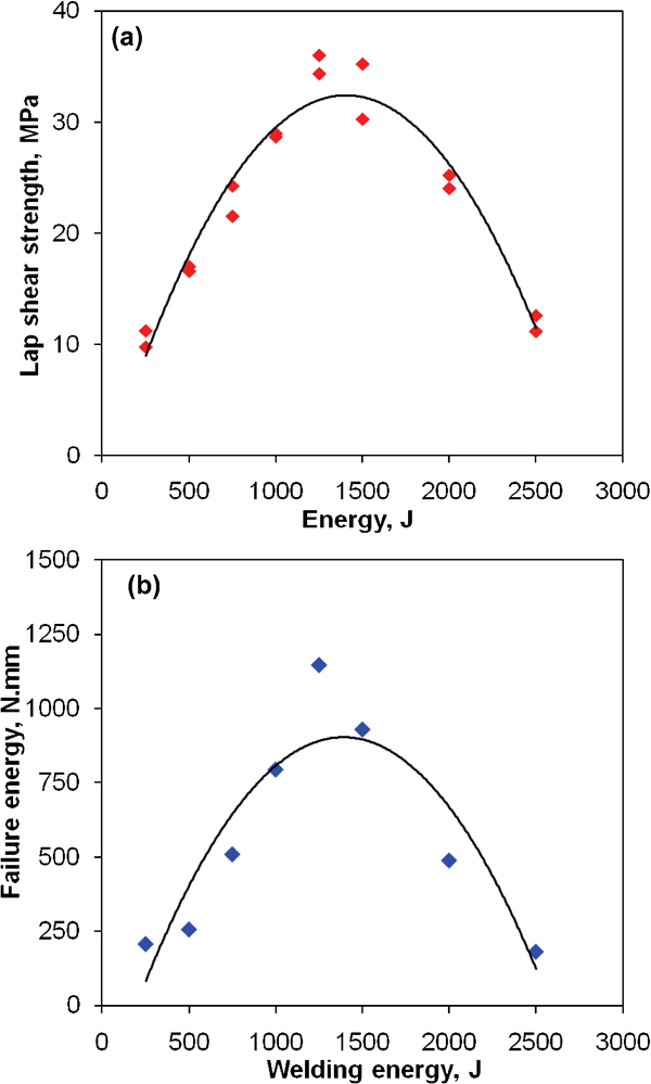
a lap shear strength and b failure energy of welded joints at different energy input levels
Conclusions
A sound joint of USW Mg alloy sheet to an Al alloy sheet was successfully achieved. The distribution and microstructure of the formed IMCs have been determined as mainly phases of Al12Mg17 and a eutectic structure consisting of Al12Mg17 and the Mg solid solution. This was confirmed by three different methods: EDS, XRD and microhardness test. As anticipated, the hardness of the IMCs is significantly higher than that of the base materials. As a consequence, brittle fractures occur at the IMCs. Cracking was found in the welded sample of 2500 J energy input and above. The maximum lap shear strength was 36 MPa at 1250 J energy input (which is much lower than the shear strength of AZ31-H24 and Al5754-O). This was a consequence of a competition between the increasing diffusion bonding arising from higher temperatures and the deterioration effect of the intermetallic layer of increasing thicknesses. Failure predominantly occurred in between the aluminium alloy and the intermetallic layer or from the cracks of the IMCs in the reaction layer. More research has to be carried out to improve the strength of the weld joint by minimising the IMC layer. A third interlayer alloy might be considered as a possible approach.
Footnotes
Acknowledgements
The authors would like to thank the Natural Sciences and Engineering Research Council of Canada (NSERC), Premier's Research Excellence Award (PREA), NSERC-DAS award and AUTO21 Network of Centers of Excellence for providing financial support. This investigation involves part of Canada-China-USA collaborative Research Project on the Magnesium Front End Research and Development (MFERD). The authors also thank Dr A. Luo, General Motors Research and Development Center, for the supply of test materials.