
Abstract
Intermetallic compound (IMC) formation at the joint line usually has strongly detrimental effect on the performance of dissimilar metal welds. To understand the formation of IMC interlayers, and explore strategies to control their growth, a model has been developed and applied to the case of dissimilar joining of aluminium and magnesium alloys using ultrasonic welding. The model accounts for microbond formation during welding, diffusion across the joint line, as well as nucleation, spreading and thickening of the first IMC layer (Mg17Al12 phase) and the formation and simultaneous thickening of the second (Al3Mg2) layer. The model predictions match measurements reasonably well and the model has been used to predict the sensitivity of IMC layer thickness to weld temperature and time.
Introduction
In many engineering applications, multimaterial structures are more efficient and better performing than the same structure produced from a single material. An important emerging example is transport, where replacing monolithic steel structures with a multimaterial solution consisting of steel, aluminium, magnesium and composites can greatly reduce vehicle weight and hence increase fuel efficiency.1 A key challenge in manufacturing such a structure is welding the different materials together to produce low cost but strong and durable joints. This paper focuses on the challenge of joining magnesium to aluminium alloys.
A major difficulty when these metals are bought into contact and interdiffuse is the formation of a brittle intermetallic compound (IMC) reaction layer. Studies of diffusion couples of aluminium and magnesium reveal that the IMC layer typically consists of two phases, Mg17Al12 on the magnesium side and Al3Mg2 on the aluminium side.2, 3 It has also been shown that the IMC layer formed between aluminium and magnesium grows very quickly and this has been attributed to unusually rapid diffusion through the IMC, although the origins of this are unclear.4
Solid state welding processes such as friction stir or ultrasonic welding are expected to produce less IMC than fusion processes due to the lower temperatures involved and lack of a liquid phase. However, IMC still forms, and is still critical in determining weld properties.5, 6 A promising solid state joining process for thin sheet material is high powered ultrasonic welding (HPUSW).7, 8 In this process, welds are formed without melting in times typically less than 1 s,8 minimising the time available for IMC formation. However, experimental studies of HPUSWs performed between magnesium and aluminium alloys have shown that although the process is rapid, a significant IMC layer still forms, and this controls the mechanical properties, particularly the fracture energy, which is low in the dissimilar joints due to easy crack propagation through the IMC layer.9
It is clear that to produce better weld properties, control of the IMC layer formation is critical. In helping to design control strategies, a model for the IMC formation is a useful tool. The aim of the present work is to develop such a model, and use it to explore the physics of the process. The primary purpose is to improve the understanding of IMC nucleation and growth by identifying the role of each variable, but the model also enables various strategies for controlling IMC formation to be investigated quickly.
Although there have been limited studies of IMC formation during dissimilar metal HPUSW, some guidance can be obtained from observations and models for diffusion bonding. Diffusion bonding occurs by local asperity contact followed by plastic collapse under a creep controlled regime, eliminating voids between contact points. Sophisticated models that can simulate this process for similar metal joining have been developed and validated for several different materials.10 It has been shown that surface roughness is an important parameter in determining the extent of bonding, with the root mean squared wavelength λq and roughness Rq parameters most applicable to capturing the roughness effect on the number of initial asperity contacts and the extent of asperity collapse needed to eliminate voids.10
For diffusion bonding of dissimilar metals, models have been developed that predict the likely compounds to form and the thickening kinetics.11 It has been demonstrated that for dissimilar metal diffusion bonding, IMC formation occurs first at local contact points followed by rapid growth along the interface and then more gradual thickening.11 The relationships between roughness measurements and asperity contact points developed for similar metal diffusion bonding and the IMC growth behaviour observed in dissimilar metal diffusion bonding have direct relevance to HPUSW of dissimilar metals. However, there are also notable differences that must be accounted for. First, in USW it is the relative movement of the two surfaces that bring asperities into contact in the initial stages, and not creep. Second, diffusion bonding is typically a slow, isothermal process whereas USW is rapid and non-isothermal.
In the present paper, a coupled model for IMC formation during HPUSW is developed by combining an existing model that predicts asperity contact and microbond formation during similar metal welding with a diffusion and reaction model that predicts IMC compound formation, spreading and thickening.
Model description
A complete model for the formation and growth of the IMC during ultrasonic welding requires combining several component submodels. The benefit of a complete model is that it enables all of the factors that control the thickness of the IMC layer to be accounted for. Such a model can be used to identify process or alloy modifications that may be useful in controlling the morphology and thickness of the IMC layer.
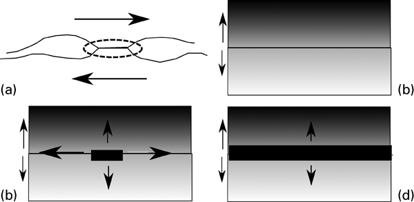
The sequence of events to be modelled starts with microbond formation in the first few milliseconds of the USW process.7 Following this, diffusion occurs across the microbonds until a critical point is reached when the IMC nucleates. These IMC islands are then able to grow both sideways and by thickening. Sideways growth is prevented when neighbouring islands begin to impinge, and eventually this impingement leads to formation of a continuous IMC layer. Once this has formed, further IMC thickening requires diffusion through the IMC layer. As the layer thickens, a transition in IMC phase may occur if there is more than one possible phase that can form. The sequence of events to be modelled is shown schematically in Fig. 1 and a diagram of how the model components interact is shown in Fig. 2.
Stages in formation of IMC during ultrasonic welding that are considered in model: IMC layer usually consists of multiple phases
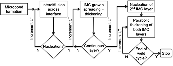
Schematic showing model components and how they are coupled The microbond model is taken from the Haarthorn7 and is run before the main model loop to predict the number of microbonds at which IMC can nucleate. The remainder of the model is run within a loop that divides the full weld thermal profile into a series of short timesteps and iterates through the full time t, temperature T profile
The model developed in this work in based on a numerical framework in which the evolution of the USW and IMC are considered over a series of very short time steps. An adaptive time step routine is used to ensure numerical accuracy, limiting the maximum growth of the IMC layer predicted in any one step to below 1 nm.
Ultrasonic welding model
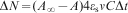
The microbonds that form during USW provide the initial sites at which diffusion will occur across the weld interface, and at which IMC will first nucleate. The microbond formation model used in this work is predicted directly from a model developed for USW of aluminium alloys by Harthoorn.7 This model predicts the increase in number of microbonds in a time interval Δt during welding as
Values and source of variables used in model

Intermetallic compound nucleation and growth model
As demonstrated by Harthoorn7 the number of microbonds saturates early during the USW and at a very small fraction of the total welding time. Therefore, for the purposes of the diffusion calculation, it is sufficient to assume that all microbonds form at approximately t = 0 (i.e. at the start of USW). Diffusion across the microbonds can then be predicted by solving Fick's second law at each timestep,12 which is done using the MATLAB partial differential equation solver.
Once interdiffusion at each microbond has reached a critical level, IMCs will nucleate and begin to grow. The minimum required critical level of enrichment to initiate IMC formation is that which is needed to produce a critical nucleus with the same composition as the IMC. The critical radius depends on the free energy change on transformation of the enriched parent metal to the IMC and the interfacial energy of the IMC. Assuming there is no great difference in the energy barrier to forming the possible IMC phases, the phase that nucleates first in the present work is expected to be Mg17Al12 since this contains the highest proportion of the fastest diffusing species (i.e. Mg).13 This is also consistent with observations of the IMC layer development in static heat treatment experiments.2,
3 Therefore, it is the critical radius r* for nucleation of this phase that must be considered

Once a nucleus has formed at a microbond, it will be able to grow. It is clear from experimental studies of IMC formation during USW,9 and also from the comparable situation during diffusion bonding,11 that the IMC islands formed early during welding first grow rapidly predominantly by spreading parallel to the join line before merging and thickening more slowly. Figure 3, discussed later, shows a typical evolution of the IMC reaction layer. The observations can be explained by considering a transition from an interfacial controlled growth regime during the IMC spreading phase to a diffusion controlled thickening regime once the IMC islands have merged.
Evolution of USW with increasing welding time for 1000 J ultrasonic weld
Growth during the island spreading phase does not require the accumulation of a long range concentration gradient towards the IMC because solute removed at the interface can be replaced by solute diffusing from the other side of the join line or along the interface. Therefore, it is assumed that the rate limit step is atom transfer across the interface from the matrix into the IMC phase, driven by the reduction in free energy. Under interface controlled growth conditions, the growth velocity can be given by standard reaction rate theory as12

As the IMC islands grow towards each other they will begin to impinge, and this will slow down their edgeways growth. Furthermore, as the IMC starts to occupy an increasing fraction of the weld interface area, it will become an increasingly effective barrier to diffusional mixing across the join line. Both of these problems were treated using the Avrami method,12 in which the true growth rate is related to the extended growth rate, which is calculated ignoring impingement effects
In addition to the growth of an IMC island by atoms jumping from the surrounding untransformed matrix as discussed above, there will also be a contribution to IMC growth due to diffusion through the IMC itself. This will become increasingly important as the IMC islands grow together to form a continuous layer, and the impingement effect discussed above leads to a slowing of the growth possible by atoms jumping from the matrix. Indeed, if Af reaches 1, then the only possibility for further thickening of the IMC layer is via diffusion through the IMC itself.
To predict growth by diffusion through the IMC layer, an existing simple diffusion kinetics model is used. In the Al to Mg case, the situation is complicated because there are two phases that can form. In the present work, the simplifying assumption is made that a continuous layer of Mg17Al12 is formed before any transformation to Al3Mg2. This assumption is made on the basis of experimental observations of the layer growth.9 Once a continuous Mg17Al12 has formed, the competitive thickening of this phase and Al3Mg2 are modelled using a simple parabolic thickening model calibrated to literature data from static diffusion couples.3 This requires two parameters for each phase, a parabolic growth constant κ0 and an activation energy for the Arrhenius law, and these were taken directly from the literature.3 The coupling together of these components into the integrated model is shown in Fig. 2. The values of all the parameters used in the model and the sources are given in Table 1.
Results
Predictions for isothermal static heat treatment
To test the model predictions, the IMC formation model was first applied to predict IMC growth during static heat treatment under isothermal conditions. Only once proven for these simple conditions was it considered sensible to apply the model to the highly complex case of USW. The parameters used in the model are shown in Table 1. The origin of the parameter is also indicated, whether it be published literature, direct measurement, or physically reasonable estimate.
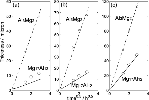
Since the thickening model is identical to that reported in Ref. 3 and uses the parameters derived from their work, the agreement between thickening predictions and measurements is identical to that reported (not shown). The model was also tested against another static thickening data set reported in the literature.2 Figure 3 shows that the model is also able to give a good prediction of the thickening kinetics for both phases in this study, across a range of temperatures. The only significant discrepancy between the predictions and measurements occurs for the Mg17Al12 layer thickness at the lowest temperature (340°C) where the model underestimates the experimental data. However, for application to USW this deviation is less important because nearly all the growth occurs during the hottest part of the thermal cycle, at above ∼400°C.
Predictions for ultrasonic welding
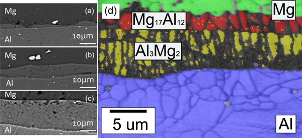
Having been demonstrated to give reasonable predictions of IMC thickening rate for the static heat treatment case (within measurement error), the model was applied to make predictions of IMC layer thickness produced by USW. A series of welds between AZ31 (magnesium alloy) and AA 6111 (aluminium alloy) were made with increasing energy levels from 320 to 1200 J. Before welding, both surfaces to be joined were ground with 1200 grit silicon carbide paper and thoroughly degreased with ethanol. Full details of these experiments and observations of the IMC development and thickness are discussed elsewhere.9 It is important to note that for the conditions reported in this paper, no partial melting was observed, although this did occur at longer welding times than those used here9 and cannot be treated by the present model. Figure 4, summarised from Ref. 9, shows how the IMC layer develops during welding with increasing weld time and also presents an electron backscatter diffraction (EBSD) map in which the two phases that make up the layer can clearly be distinguished. Consistent with the proposed mechanism for IMC layer formation outlined in Fig. 1 it can be seen that the IMC forms first as isolated islands before rapid sideways growth, merging and thickening. The island spacing measured from Fig. 4a and similar micrographs indicates a mean centre to centre distance of 18 μm, which is on the order of the roughness wavelength (11 μm).
Predictions of thickening kinetics compared to literature data:2 lines: model; points: experiment
The EBSD map corresponds to a weld time by which a continuous IMC layer has formed in which two phases are growing together. The ratio between the thickness of the two IMC phases (Mg17Al12 and Al3Mg2) is ∼1∶2, which is similar to that reported from isothermal static heat treatment experiments.2, 3
The measured thermal histories for the four experimental welds are shown in Fig. 5a. These measurements were obtained from a thermocouple placed at the weld join line.9 The measurements were repeated at least five times to ensure that the results were reproducible. These profiles were used as inputs to the IMC formation model. Eventually, it is intended that the model will be fully coupled and will take as inputs the thermal profiles predicted by a process model for dissimilar metal USWs, which is currently in development.
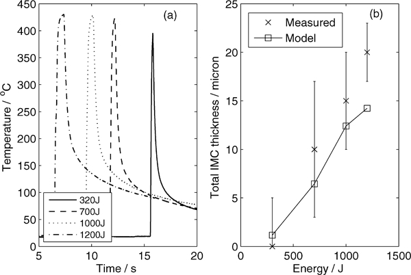
a measured thermal cycles for ultrasonic welds performed at different energies (times offset to clarify plots); b predicted and measured total IMC layer thickness
The measured and model predicted total IMC layer thickness (the sum of both phases) are compared in Fig. 5b. The model predictions show a reasonable agreement with the experimental data given the nature of the approximations used and the large error bars on the measurement, which arise because the layer thickness is not completely uniform but is characterised by peaks and troughs, as can be seen in Fig. 3. The model predictions lie within the range of experimental error for all conditions except the highest weld energy (long welding times) where the model underpredicts. This may be due to a diffusion enhancing effect of the deformation during USW,16 which is not included in the model. However, the fact that even without accounting for deformation a reasonable prediction is obtained suggests that in this dissimilar combination the influence of deformation on layer growth cannot be as large as previously reported for the Al–Zn USW where no IMC is formed.16
A full set of model predictions is shown in Fig. 6 for the example of the 1000 J weld (corresponding to the observations in Fig. 4). Figure 6a shows the predicted evolution of the number of microbonds (with the temperature profile for comparison). It can be seen that the number of microbonds is predicted to saturate very quickly (within the first 0·1 s of the welding process). Figure 6b shows the predicted evolution of the fraction of USW interface covered in IMC. For the weld conditions considered, it can be seen that ∼45% of the total weld area is predicted to be covered in IMC at the end of the joining process. Figures 6c shows the predicted diameter of the IMC islands and their thickness.
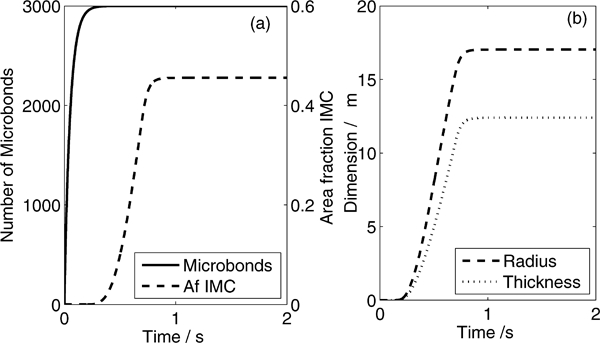
Model outputs for 1000 J ultrasonic weld
Nucleation of the first IMC island is predicted to occur early during the weld cycle, at about 0·4 s. This is shortly before the peak temperature is reached (at ∼0·8 s). Once nucleated, the IMC layer is able to grow rapidly, since the nucleus is surrounded by heavily supersaturated matrix and the frequency of atomic jumps across the interface is high. The IMC layer continues to grow rapidly until the temperature falls below ∼300°C; this occurs after ∼1 s for the weld energy used here (1000 J). The process of IMC nucleation and growth is therefore complete in a very short period of time, but is rapid enough to lead to a layer approaching 12 μm in thickness.
Application of model
One advantage of a model, even a simple one such as presented here, is that it enables speculation about the effect of various process parameters to be tested, isolating only one variable. This is of particular value in highly coupled processes such as ultrasonic welding, where experimentally it can be impossible to change one variable without influencing others (e.g. temperature).
Example predictions showing the sensitivity of the IMC layer thickness to temperature and weld time shown in Fig. 7. The peak temperature reached during USW is essentially limited by the onset of melting, and so is relatively insensitive to weld energy (as is evident from the measured thermal cycles in Fig. 5a). However, even a small difference in peak temperature has a significant predicted effect on IMC thickness. Figure 7a shows the influence of a 5°C increase or decrease in peak temperature obtained by scaling the thermal profile from the weld performed at 1000 J. This change in peak temperature of 1·2% has produced a 14% predicted change in the layer thickness, indicating the sensitivity of IMC layer thickness to temperature. Not only is the layer predicted to be thicker for a higher temperature, but the fraction of the interface covered by IMC is greater. Figure 7b shows the effect of a large (50%) change in weld time. Clearly, the shorter the weld time, the thinner the layer. The model predicts that there is an approximately proportional relationship between the total welding time and layer thickness, so halving the welding times leads to a halving of the total final layer thickness.
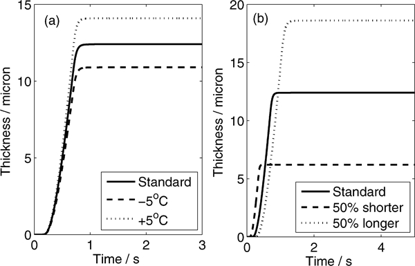
Predicted effect of a increasing or decreasing peak temperature by 5°C and b increasing or decreasing weld time by 50% compared to standard 1000 J weld
Conclusions
A new model has been developed to predict IMC formation during the dissimilar USW of aluminium and magnesium alloy by ultrasonic welding. The main conclusions are summarised below.
The IMC formation model has been tested against literature data from static diffusion couple experiments and gives good agreement, correctly predicting both the total IMC thickness and the thickness of the two phases in the layer (Mg17Al12 and Al3Mg2).
The same model applied directly to USW gives a reasonable prediction of the final IMC layer thickness for welds performed over a wide range of weld energies. This implies that the deformation associated with USW does not have a large role in accelerating the growth of the IMC layer in the present case.
The model has been used to explore the sequence of events that occurs during USW of dissimilar metals. It is predicted that initial microbond formation and IMC nucleation occur early during the process, typically at <0·5 s. Once nucleated at individual microbonds, IMC islands grow by spreading and thickening under interface control, which is a rapid process and is complete within <1 s. Once neighbouring islands impinge, further thickening requires diffusion through the IMC, which is a comparatively slow process.
The model has been demonstrated by performing a sensitivity analysis to changes in welding time and temperature. The model predicts a near proportional relationship between welding time and layer thickness, and an exponential dependence of layer thickness on welding temperature.
Footnotes
Acknowledgements
This work was funded by the Engineering and Physical Sciences Research Council (EPSRC) Portfolio Partnership on Light Alloys for Environmentally Sustainable Transport (EP/D029201/1). Jaguar Landrover and Magnesium Elektron are thanked for the provision of materials used in this study.