
Abstract
Aluminium alloy A6061-T6 or magnesium alloy AZ31 sheet was welded to steel sheet by a friction stir spot welding technique using a scroll grooved tool without a probe. The material flow in the nugget of the Mg/steel weld was less than that in the Al/steel one. The Al/steel weld exhibited higher static tensile–shear strength than the Al/Al weld, while the strengths of Mg/steel and Mg/Mg welds were comparable. Tensile–shear fatigue tests were performed using lap shear specimens of both dissimilar and similar welds. The dissimilar welds exhibited nearly the same fatigue strengths as the similar ones. The effective nugget size in the dissimilar welds was defined as the area where Al or Mg alloy remained on the steel side after static fracture. When the fatigue strengths of dissimilar welds were evaluated based on the effective nugget size, the normalised fatigue strengths of Al/steel and Mg/steel welds were comparable.
Introduction
Automobile industries are paying attention to aluminium and magnesium alloys because they are attractive as lightweight structural materials to achieve high performance and efficiency. However, steels are still widely used for structural components because of their high absolute strength and good cost efficiency. Hence, it is becoming very important to join thin Al or Mg sheets to thin steel ones to fabricate structural components. The joining techniques of thin sheets include resistance spot welding, rivets, self-piercing rivets, clinching, friction stir spot welding (FSSW) and so forth. Whatever technique is used for joining, the strength properties, in particular the fatigue properties, of welds are critical. Thus, it is vital to elucidate their fatigue behaviour and fracture mechanism.
Although there are many joining techniques, friction stir welding or FSSW is widely applied for the fabrication of dissimilar welds, such as Al/steel,1– 6 Al/copper,5 Al/Mg7 and Mg/steel1 combinations. That is because friction stir welding and FSSW are solid state welding processes, and it is possible to avoid the formation of thick intermetallic compounds along the interface, which usually leads to the brittle fracture of dissimilar welds. Recently, some studies on the fabrication of dissimilar welds by FSSW have been reported, but detailed or comparative studies of fatigue behaviour of dissimilar welds are still very limited.6
In the present study, tensile–shear fatigue tests have been performed using lap shear specimens of FSSW joints. Al/steel and Mg/steel dissimilar welds and Al/Al and Mg/Mg similar welds were used for the experiments. The fatigue behaviour and fracture mechanism of each joint were investigated, and subsequently, comparison among those welds was made.
Experimental
Material and specimen
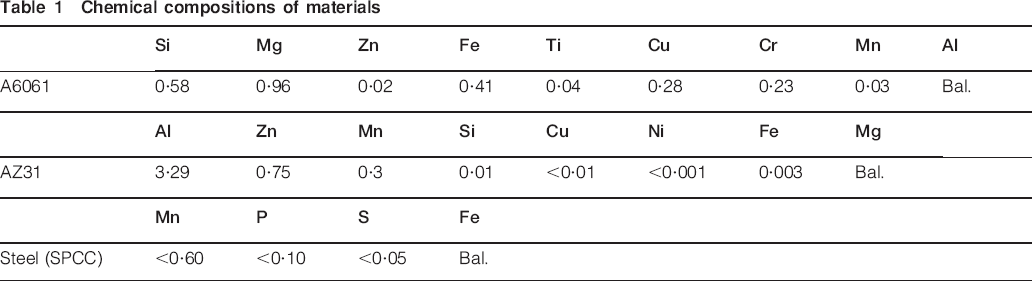
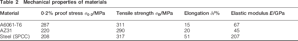
The materials used in this investigation are A6061-T6 aluminium alloy, AZ31 magnesium alloy and cold rolled low carbon steel sheets, whose thicknesses are 2 mm. AZ31 is a rolled plate; thus, it should be noted that the plate has a texture due to the rolling process. Styczynski et al. found a strong tendency to build a symmetrical splitting of the {0 0 0 2} basal texture in rolled AZ31, where the splitting occurred about ±15° in the rolling direction.8 The chemical compositions and mechanical properties of the materials are summarised in Tables 1 and 2 respectively. The low carbon steel sheet is classified as SPCC type in the Japanese Industrial Standard G3141. The microstructures of the materials observed on the cross-section are revealed in Fig. 1. Grains of A6061 are elongated due to the rolling process, while those of AZ31 and steel are equiaxial. AZ31 has much finer grains than the others. The configuration of the lap shear specimen is depicted in Fig. 2. The specimens were fabricated using two 30×100 mm sheets with a 30×30 mm overlap area and contained a spot weld by FSSW at the centre of the overlap area. In Al/steel and Mg/steel dissimilar welds, steel was used as the lower sheet. For comparison, Al/Al and Mg/Mg similar welds were also fabricated. In all the welds, the rolling direction was perpendicular to the longitudinal direction of the specimens.
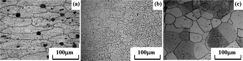
Microstructures of materials observed on cross-section of plate
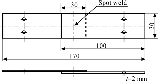
Configuration of lap shear specimen
Chemical compositions of materials
Mechanical properties of materials
Tool geometry and welding conditions
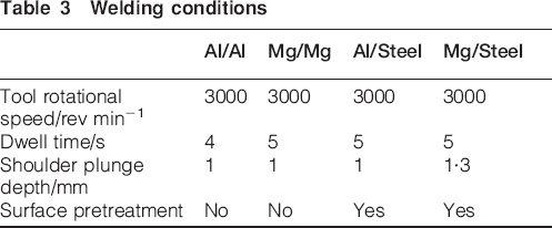
The scroll grooved tool without a probe is shown in Fig. 3. The performance of this tool is described in the work of Tozaki et al. 9 The welding conditions for similar and dissimilar welds are summarised in Table 3. These conditions were defined from pretensile tests. In all cases, the plunge rate was 10 mm min−1. Before the fabrication of dissimilar welds, surface pretreatment was applied. The contact surfaces of Al, Mg and steel sheets were polished to a mirror finish before welding in order to achieve better tensile performance of dissimilar welds.6, 10
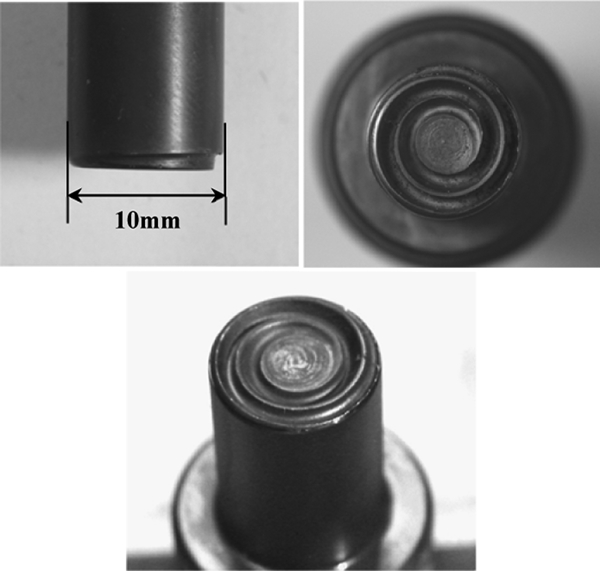
Scroll grooved tool without probe
Welding conditions
Procedures
An electrohydraulic fatigue testing machine was used for both static tensile–shear tests and fatigue tests. Fatigue experiments were performed using a sinusoidal waveform under a load control with a frequency of 10 Hz and a stress ratio of R = 0·1 in laboratory air at ambient temperature. After tensile and fatigue tests, fracture surfaces were examined in detail using a scanning electron microscope (SEM) equipped with a backscattered electron detector.
Similar welds
Weld structures
Figures 4 and 5 reveal examples of the macroscopic and microscopic weld structures observed on the longitudinal sections of the nuggets in Al/Al and Mg/Mg similar welds. The boundary between the upper and lower sheets can be seen in the Al/Al similar weld, indicated by the broken line in Fig. 4a. It should be noted that the boundary could be recognised after etching, indicating that joining between the upper and lower sheets had been successfully achieved. The upward material flow from the lower sheet could be recognised, as shown by the boundary and Fig. 4c and d, which are magnified views of areas B and C in Fig. 4a. The material flow was induced by the scrolled groove on the shoulder surface.9 On the other hand, the boundary is rather straight in the Mg/Mg weld (Fig. 5a). Figure 5d is the magnified view at area C in Fig. 5a and reveals that the upward material flow is weaker compared with the Al/Al weld, even though the welding parameters are nearly the same (Table 3). Sun et al. 11 and Yun et al. 12 investigated the material flow in the nugget of Mg/Mg welds fabricated by a tool with a probe and had reported that the material flow in the Mg/Mg weld was less than that in the Al/Al weld.
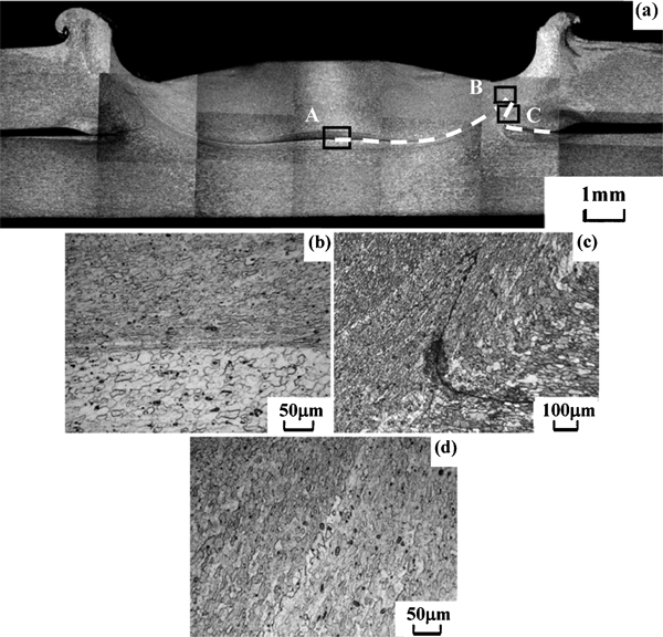
Weld structures observed on cross-section of nugget in Al/Al similar weld
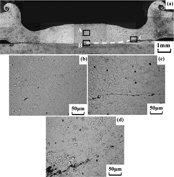
Weld structures observed on cross-section of nugget in Mg/Mg similar weld
Equivalent tensile–shear strength under static and fatigue loading
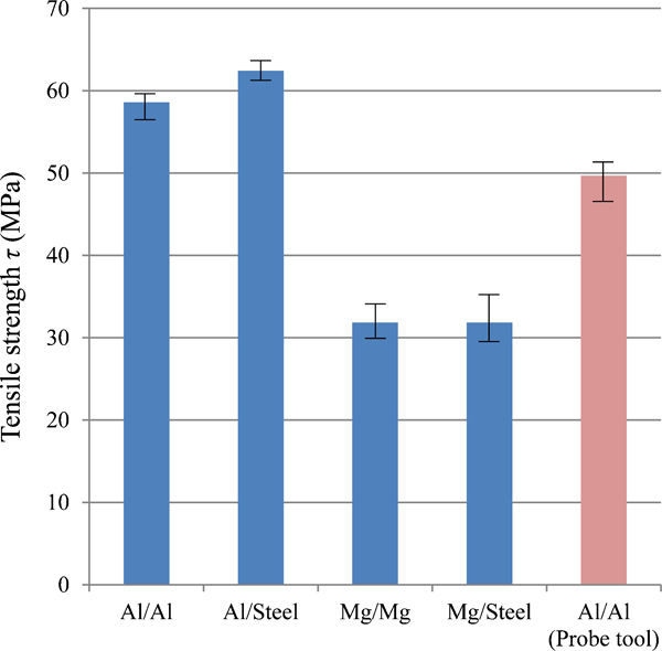
The average equivalent tensile–shear strengths of five specimens are summarised in Fig. 6. The tensile–shear forces (N) were normalised by the nugget area (mm2), where the nugget diameter was supposed to be correspondent with the shoulder diameter of the tool (10 mm). The equivalent tensile–shear strengths are 59 MPa (4·6 kN in terms of net load) and 32 MPa (2·5 kN) for Al/Al and Mg/Mg welds respectively. In Al/Al similar welds, the combinations of rotational speeds of 2000 and 3000 r min−1, plunged depths of 0·5–0·9 mm and dwell times of 1–8 s had all been tested by Tozaki et al. 9 Subsequently, the tensile–shear force of lap shear specimens with a plate thickness of 2 mm varied from 0·4 to 4·6 kN. Thus, the welding condition in Table 3 was optimal for an Al/Al similar weld. The equivalent tensile–shear strength of an Al/Al similar weld fabricated by a conventional concave tool with a probe9 is also shown in Fig. 6. The shoulder diameter of the conventional tool is 10 mm and the same as the scroll grooved tool. As shown in Fig. 6, the Al/Al weld made by the scroll grooved tool exhibits higher equivalent tensile–shear strength than the weld fabricated by the conventional tool. In Mg/Mg similar welds, the welding condition was set to be similar to that of the Al/Al weld, while the dwell time of 4 s gave slightly lower tensile–shear force (2·3 kN), so that the dwell time was raised to 5 s. It is not clear whether the condition for the Mg/Mg weld was optimal or not, but a pullout type fracture occurred in the Mg/Mg weld, indicating that high bonding strength was achieved by the welding condition in Table 3. Figure 7 shows the relationship between the maximum shear stress in the nugget τmax and the number of cycles to failure Nf. Al/Al welds have higher fatigue strengths than Mg/Mg ones, and the scroll grooved tool achieved higher fatigue strengths in the Al/Al weld than the conventional tool.9
Tensile–shear strengths of similar and dissimilar welds
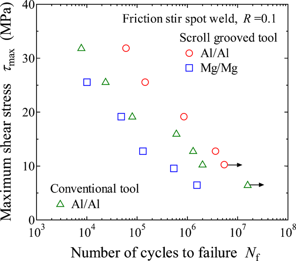
Relationship between maximum shear stress in nugget τmax and number of cycles to failure Nf
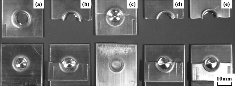
Subsequently, the failure modes of the welds were investigated in detail, because the failure modes can affect the strengths of FSSW joints.13 The failure modes of Al/Al welds under static and fatigue loading conditions are summarised in Fig. 8. Under static loading condition, pullout type fracture occurred, as shown in Fig. 8a. The same pullout type fracture was also identified in Mg/Mg welds. It should be noted that the shear type fracture through the nugget did not take place in Mg/Mg welds under the static loading condition. This indicates that good adhesion was achieved between the upper and lower sheets, even if the material flow in the nugget was less than in the Al/Al welds, as shown in Figs. 4 and 5. Under the fatigue loading condition, the fatigue crack grew through the lower sheet in Al/Al welds irrespective of the load level (Fig. 8c and d). Figure 9 shows the failure modes in Mg/Mg welds under the fatigue loading condition. As shown in the figure, the failure modes are dependent on τmax, and the transition of failure mode was recognised. At the highest load (Fig. 9a), pullout type fracture occurred, similar to the fracture under static load, while the fatigue crack grew through the upper sheet at the medium and low load levels. Although the transition of failure mode occurred in Mg/Mg welds under fatigue loading, the transition behaviour could not account for the different fatigue strengths between Al/Al and Mg/Mg welds because the failure modes of these welds were nearly the same at the medium and low load levels.
Macroscopic appearances of fractured Al/Al similar welds
Macroscopic appearances of fatigue fractured Mg/Mg similar welds
The Mg/Mg welds exhibited ∼46% lower static strength and 45% lower fatigue strengths in the finite fatigue life region than the Al/Al welds. The 0·2% proof stress of the Mg alloy is just 23% lower than the Al alloy, as shown in Table 2, indicating that the lower strengths of Mg/Mg welds could be attributed to other reasons besides its lower proof stress. It is considered that the rotation of the nugget played an important role. When lap shear specimens are subjected to static and fatigue tensile–shear tests, rotation around the nugget occurs easily, and the rotation leads to the load component becoming perpendicular to the nugget, which has a detrimental effect on the strength of the welds.14 The elastic moduli of Mg and Al alloys are 45 and 67 GPa (Table 2) respectively, and so rotation around the nugget takes place more easily in the Mg/Mg weld because of the lower rigidity of the base alloy. Consequently, the lower static and fatigue tensile–shear strengths of Mg/Mg welds compared with Al/Al welds can be attributed to both the lower proof stress of Mg alloy itself and the larger rotation around the nugget in the Mg/Mg weld.
Dissimilar welds
Weld structures
Figures 10 and 11 reveal the macroscopic and microscopic weld structures observed on longitudinal sections of the nuggets in Al/steel and Mg/steel dissimilar welds. The boundaries between the upper and lower sheets are straight in both dissimilar welds (Figs. 10a and c and 11a and d) because the steel sheets were not stirred. Figure 10d and e shows the magnified views of areas C and D in Fig. 10a. Based on these magnified views, the severely stirred zone was defined by the broken line, as shown in Fig. 10a. In Mg/steel weld (Fig. 11a), a severely stirred zone was found from the boundary between dark and light grey areas, as shown by the broken line. The severely stirred zone is slightly smaller in the Mg/steel weld than in the Al/steel one, corresponding to the smaller material flow observed in the Mg/Mg similar weld than in the Al/Al one (Figs. 4 and 5).
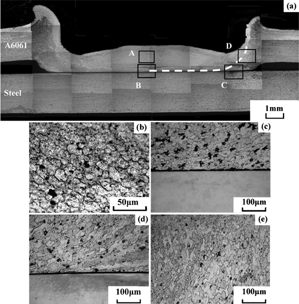
Weld structures observed on cross-section of nugget in Al/steel dissimilar weld
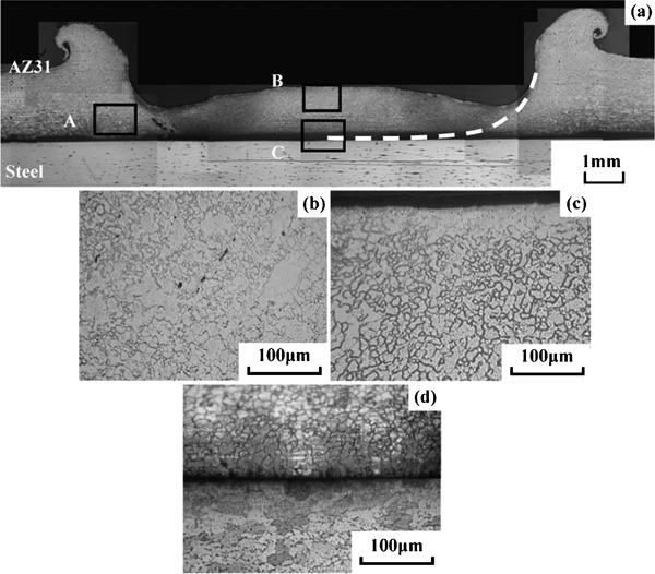
Weld structures observed on cross-section of nugget in Mg/steel dissimilar weld
Equivalent tensile–shear strength under static loading
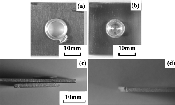
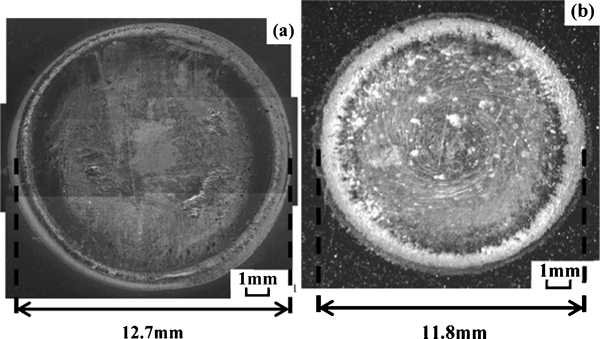
The equivalent tensile–shear strengths are summarised in Fig. 6. The Al/steel dissimilar weld exhibits higher equivalent tensile–shear strength [62 MPa (4·9 kN)] than the Mg/steel one [32 MPa (2·5 kN)]. In the Al/steel welds, several combinations between tool rotational speed and dwell time had been tried, keeping the plunge depth of 1 mm constant. Subsequently, the following results were obtained, 2500 r min−1–5 s: 0·6 kN, 3000 r min−1–4 s: 4·8 kN, 3000 r min−1–5 s: 4·9 kN, 3500 r min−1–5 s: 4·5 kN, indicating that the welding condition in Table 3 was optimal. However, the tensile–shear force was insensitive to the welding conditions when the tool rotational speed was >3000 r min−1. Similar welding conditions were used for the Mg/steel weld, while the plunge depth of 1 mm gave a slightly lower tensile–shear force of 2·2 kN. Consequently, the plunge depth was raised to 1·3 mm and achieved 2·5 kN. It is not clear if the welding condition for the Mg/steel weld was optimal or not, but in the Al/steel weld, the tensile–shear force was insensitive to the welding conditions. Thus, it is considered that the condition in Table 3 gave a high tensile performance for the Mg/steel weld. In comparison with the similar welds, the equivalent tensile–shear strength of the Al/steel dissimilar weld is higher than the Al/Al similar one, while the equivalent tensile–shear strengths are nearly the same between the Mg/steel and Mg/Mg welds. The SEM images of the steel side fracture surfaces of the Al/steel and Mg/steel welds are shown in Fig. 12, revealing that the shear fracture along the interface occurred under static loading conditions in both welds. It should be noted that the diameter of nugget observed on the steel side fracture surface is slightly smaller in the Mg/steel welds, which agrees with the smaller size of the severely stirred zone on the cross-section (Figs. 10a and 11a). As shown in Fig. 12, the diameter of the nugget on the fracture surface was larger than the shoulder diameter. However, the shear stress was calculated using the shoulder diameter, as mentioned in the section on ‘Equivalent tensile–shear strength under static and fatigue loading’, because the nugget size could not be defined on the fracture surfaces in similar welds due to the pullout failure mode (Fig. 8a and b).
Images (SEM) showing steel side fracture surfaces of dissimilar welds
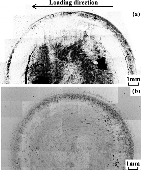
The steel side fracture surfaces of both dissimilar welds were observed using the backscattered electron image (BEI) of SEM. In a BEI, materials with different atomic weights can be distinguished by the different contrasts. Figure 13 reveals the BEIs of the steel side fracture surfaces shown in Fig. 12. The dark and bright areas correspond to light weight alloy (Al or Mg) and steel respectively. The different contrasts between Fig. 13a and b depend on the different SEM equipment, where a Hitachi S-4300 and S-3000N were used for the BEI observations of Al/steel and Mg/steel welds respectively. It should be noted that the different contrasts do not affect the accuracy in detecting different alloys. It is clear that the dark area in the Al/steel weld (Fig. 13a) is wider than that in the Mg/steel one (Fig. 13b). Al remains near the centre of the nugget in the Al/steel welds, while steel is exposed near the centre in the Mg/steel one. This indicates that higher bonding strength was achieved in the Al/steel welds, where the material flow was greater. In the Al/steel welds, it is believed through TEM observation that the bonding between Al and steel is achieved due to the formation of a thin intermetallic compound layer along the interface between Al and steel.1, 2, 5 However, it is known that Mg and steel hardly form an intermetallic compound at all.15 Liyanage et al. 1 fabricated AM60/DP600 steel dissimilar friction stir spot welds, and the welds showed no evidence of intermetallic formation. They reported that a Zn layer on DP600 steel resulted in melted eutectic material (α-Mg+MgZn) and cracking. In this research, however, SPCC steel does not have a Zn layer, so further microscopic investigations are necessary to clarify the joining mechanism between Mg and steel.
Backscattered electron images of steel side fracture surfaces of dissimilar welds
Tensile–shear strength under fatigue loading
The relationships between τmax and Nf in both similar and dissimilar welds are indicated in Fig. 14. The Al/steel welds have higher fatigue strengths than the Mg/steel ones. It is clear that the fatigue strengths between dissimilar and similar welds are nearly the same, regardless of the welding alloys. Fatigue failure modes were investigated in detail, and it was found that a transition of failure mode occurred in the Al/steel weld,6 where a fatigue crack grew through the interface between the upper and lower sheets at high and medium load levels, but grew through the upper sheet at the lowest load level. On the other hand, a fatigue crack grew through the interface in Mg/steel welds, regardless of load levels. However, the fatigue fracture modes between Al/steel and Mg/steel welds are nearly the same, with fatigue crack growth through the interface dominant. It indicates that the lower fatigue strength of the Mg/steel weld could not be attributed to the fracture mode.
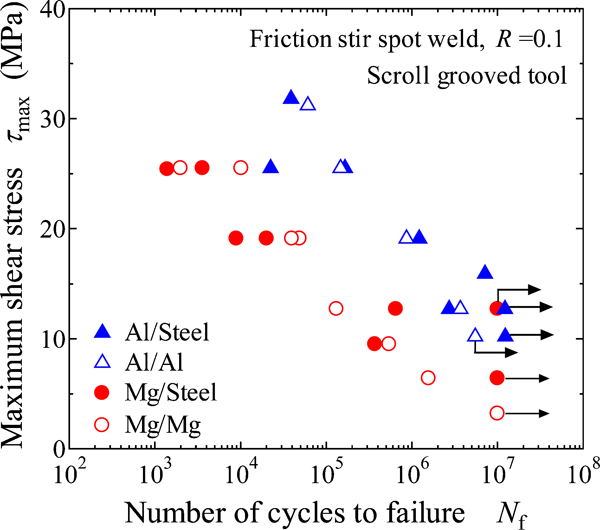
Relationship between maximum shear stress in nugget τmax and number of cycles to failure Nf in similar and dissimilar welds
The Mg/steel welds exhibited ∼49% lower tensile–shear static strength and 47% lower fatigue strengths in the finite fatigue life region than the Al/steel welds. As mentioned above, the lower 0·2% proof stress of Mg alloy could not account for the lower tensile–shear strength because the proof stress of Mg alloy is just 23% lower than Al alloy (Table 2). In similar welds, the rotation around the nugget played an important role because the Mg alloy had a lower elastic modulus (45 GPa). In dissimilar welds, however, the rotation around the nugget during tension is dominated by rigid steel plates, whose elastic modulus is 208 GPa, so the effect of rotation should be the same between Al/steel and Mg/steel welds. When the effective nugget size was defined as the area where Al or Mg remains on the steel side fracture surface after the static tensile–shear tests, the effective nugget size is smaller in the Mg/steel weld than in Al/steel one, as shown in Fig. 13. Furthermore, the shear type fracture through the interface was dominant under both tensile and fatigue loading conditions in both dissimilar welds. Consequently, the lower static and fatigue strengths of Mg/steel welds could be attributed to both the lower proof stress of the Mg alloy and the smaller effective nugget size in the Mg/steel welds.
As the failure modes of the dissimilar welds under static and fatigue loading conditions were nearly the same, where shear type fracture through the nugget occurred, the fatigue strengths were normalised by the static strength, as shown in Fig. 15. The normalised fatigue strengths of both dissimilar welds showed good agreement, indicating that the fatigue strength could be roughly estimated from the static strength.
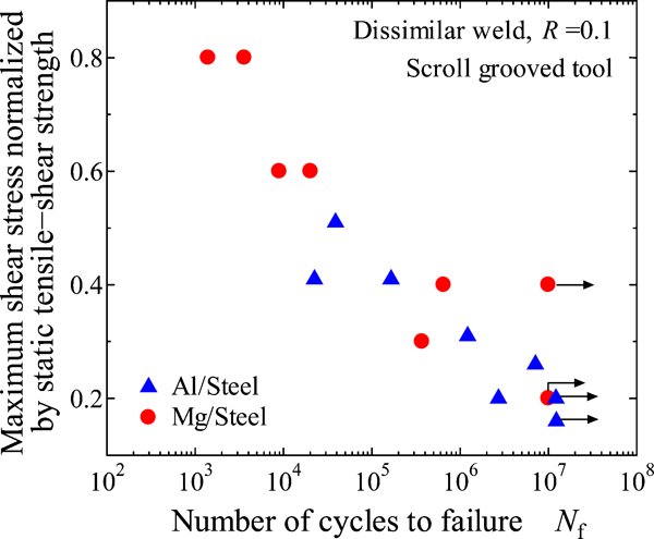
Fatigue strengths in terms of maximum shear stress normalised by static tensile–shear strength
Attention must be paid to the fact that this kind of estimation should be performed when the failure modes are the same under static and fatigue loading conditions. Subsequently, the fatigue strengths of dissimilar welds were estimated based on the effective nugget size, namely, the maximum loads of fatigue tests divided by the effective nugget size τmax, eff. In this case, the effective nugget size was defined from Fig. 13, The results are shown in Fig. 16. The fatigue strengths in terms of τmax, eff are nearly the same between both dissimilar welds, and τmax, eff (Fig. 16) gives better agreement between the Al/steel and Mg/steel welds than the fatigue strengths normalised from the static strengths (Fig. 15). It indicates that the effective nugget size could be the controlling factor of the fatigue strengths of dissimilar welds, and it is important to increase the effective nugget size to improve the fatigue performance of dissimilar welds.
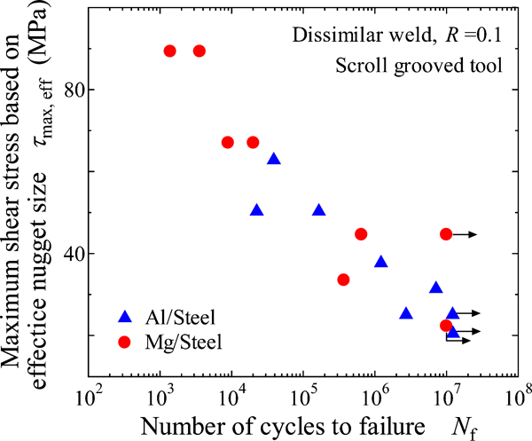
Fatigue strengths in terms of maximum shear stress based on effective nugget size τmax, eff
Conclusions
Aluminium or magnesium alloy sheets were welded to steel sheets by FSSW using a scroll grooved tool without a probe. Tensile–shear fatigue tests have been performed using lap shear specimens of similar and dissimilar welds. The fatigue behaviour and fracture mechanism of each joint were evaluated, and comparison was made between the Al/steel and Mg/steel welds.
The material flow in the nugget of the Mg/Mg similar weld was less than that in the Al/Al one. The tensile–shear static and fatigue strengths of the Al/Al similar welds were higher than those of the Mg/Mg ones because of the higher proof stress and elastic modulus of the Al alloy.
The Al/steel dissimilar weld exhibited higher equivalent tensile–shear strength than the Al/Al similar one, while the equivalent tensile–shear strengths of the Mg/steel dissimilar and the Mg/Mg similar welds were comparable.
In both Al/steel and Mg/steel dissimilar welds, the tensile–shear fatigue strengths were comparable to those of similar welds.
The effective nugget size was defined as the area of Al or Mg on the steel side fracture surface after the static tensile–shear tests. When the maximum shear stress was estimated based on the effective nugget size, the fatigue strengths were comparable between the Al/steel and Mg/steel dissimilar welds.
The higher static and fatigue strengths of the Al/steel dissimilar weld could be attributed to the high proof stress of the Al alloy and the larger effective nugget size of the Al/steel dissimilar weld.