
Abstract
Longitudinal residual stresses in beam welds ranging at the value of the local yield strength can diminish the lifespan of components. To extend the service life of welds special methods of welding residual stress reduction were developed earlier which are however not effective for beam welds in complex component geometries. Application of beam welding sources for post-welding heat treatment of components has become a flexible tool for reducing longitudinal stresses in beam welds. Such heat treatment in a specific transversal distance to the weld by a defocused beam results in huge stress reductions depending on the used process parameters. Experimental results for ferritic and austenitic steels reveal weld stress reductions to up to compressive stresses. For different materials and diverse material thicknesses special process parameter regions have to be used in this procedure. At a transmission component this procedure shows a stress reduction by >300 MPa.
Introduction
High longitudinal residual stresses are generated in narrow beam welds during cooling and shrinking amounting to the local yield strength of the material.1 The material beside the weld resists this thermal shrinkage and constrains the weld. The resulting high longitudinal stresses can diminish the service life of welded components due to increased stress corrosion cracking2, 3 or component deformation caused by superposed service loads.2– 6 In the last decades several methods for residual stress reduction in welds were developed. The first thermal procedure, i.e. stress relief annealing, was based on global heat treatment of the component in large annealing furnaces.2, 7, 8 Later, local heat treatment of smaller component areas was used to mitigate distortions and stresses by flame straightening.9, 10 However, most of these methods are not effective enough for beam welds or they are expensive.7, 8, 11– 16 In Refs. 17 and 18 a new post-welding heat treatment method for residual stress reduction in beam welds of specimens made of 5 mm thick ferritic steel S355J2+N is presented. In this stress mitigating process the beam source is applied in a longitudinal distance dx or with a time delay tx after welding in a defocused mode (beam radius r of several millimetres) for heat treatment of the material in a certain transversal distance dy to the weld (cf. Fig. 1) in a second work step. The defocused beam is used to heat up the material to several hundreds of degrees Celsius. Owing to this heating process this material region expands and stretches the weld in a small order. The compressive stresses induced in the heated zones relax at these high temperatures because of the decreasing yield strength while heating. Small plastic deformations are generated by this relaxation process in the heated region. During cooling the thermal shrinkage of the treated zones causes a compression of the material between the heated zones and the weld. This intermediate material constrains the weld while cooling down from melting temperature and leads to the high longitudinal stresses in the weld. Because of the compression of this intermediate region the resistance to weld shrinkage is reduced19 and thus the longitudinal stresses in the weld can be reduced.
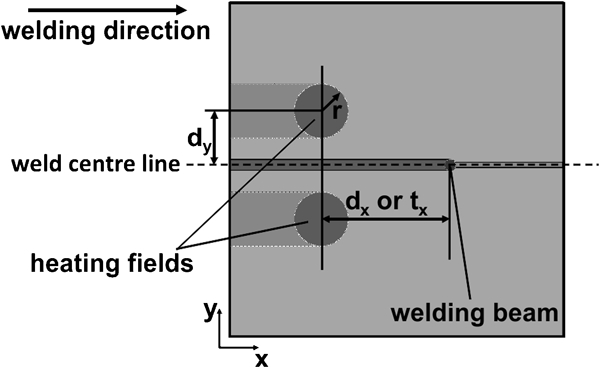
Heat treatment process scheme with important geometric process parameters: heat source radius r, longitudinal distance dx/time delay tx between welding and heat treatment and transversal distance between weld and heat treatment dy
Because of the required low plastic deformation it is essential to generate temperatures in the heated zones which correspond to a large reduction in yield strength. This is why temperatures of ∼700°C are necessary for ferritic steels in this stress mitigating procedure. Other important process parameters are the transversal distance of the heat treatment centre to the weld, the defocused beam radius and the travel speed of this heat treatment. The transversal distance depends on the used beam radius and should be in an order of the radius plus 10–15 mm. If the heat treatment is conducted at smaller distances, enhanced conductive reheating of the weld reduces the stress mitigating potential of this method. For larger distances than recommended, the intermediate material volume is increased and results in lower compression of the intermediate material. This leads to decreased unloading of the weld.
From the investigation of the other process parameters it was concluded that the reduction of the longitudinal stresses in the weld is increased by applying larger beam radii and/or lower travel speeds in the heat treatment. Both of these measures prolong the exposure time and enhance the depth effect. Furthermore, for lower weld temperatures the weld is strained to a larger degree during the heat treatment. As a consequence, the stress reducing effect is increased if the weld cools down to ambient temperature before the heat treatment is performed.
This method is similar to thermal tensioning based low stress no distortion techniques8, 11– 14 and to the online method which uses heating elements to generate tensile stresses next to the weld that interrupt regions of compressive stresses and mitigate distortion in welding of stiffened panels in the ship building industry.20, 21 Defocused laser beams applied for such heat treatments provide a more flexible tool for welding residual stress mitigation in beam welds because they obviate the need for clamps, cooling and heating elements or flame heaters and cooling jets. Such equipment demands large contact surfaces, wide welds and low welding speeds to generate the specific temperature profile in the components. These previous techniques are only effective at beam welding speeds lower than 8 mm s−1.16 However, beam welding is normally conducted at speeds higher than 10 mm s−1. The method which uses the defocused beam for the heat treatment after welding in a second work step separated from the welding process can be performed without influencing the welding process and without any additional equipment or contact surfaces. These advantages enable an economical reduction of the high longitudinal stresses in beam welds in complex component geometries.
This procedure was adopted in the study reported here for three different test series examining different materials and varied material thicknesses. It was in addition applied for the first time to a complex component from the automotive industry with different beam weld geometries.
Experimental
At first the process parameters chosen for the research work at 5 mm thick ferritic steel S355J2 were used for tests (series 1) at 3·8 mm thick austenitic steel X8CrMnNi19–6–3 which is widely used in the vehicle manufacturing. Owing to the different material properties of austenitic steel compared to ferritic steels it is essential to verify the suitability of the process parameters for the required temperatures to be generated during the quasi-simultaneous post-welding heat treatment on both sides beside the weld and for the transversal distance of the heat treatment to the weld.
A 16 kW disc laser coupled with a conventional laser welding optics (focal length of 300 mm) was used for welding in all tests. In each quadratic specimen with 200 mm edge length a linear bead on plate weld was generated (shown schematically in Fig. 1). The 3·8 mm thick austenitic specimens were welded in the experimental set-up illustrated in Fig. 2 using a beam power of 3·8 kW and a welding speed of 33·3 mm s−1.
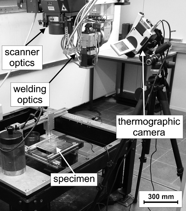
Experimental set-up with specimen and two laser optics above
Post-welding heat treatment with the defocused laser beam was started in a separate work step. It was conducted on both sides of the weld quasi-simultaneously by using the fast beam deflection with the laser scanner optics (focal length of 450 mm). In performing the heat treatment the defocused beam travels with a speed of 5 mm s−1 parallel to the weld on one side for 0·2 s. After the 0·2 s the beam is deflected at a deflection speed of 1 m s−1 to the other side of the weld and also travels parallel to the weld for 0·2 s before it is deflected to the other side back again. With this beam scanning a quasi-simultaneous heat treatment is generated.
To justify a defocused beam and for obtaining two different beam radii (11·4 and 14·6 mm), two different distances were set between the scanner optics and the specimen level. At these distances the power density distribution in the beam was measured to quantify the beam radius which includes 86% of the beam power. Subsequently, the temperature was measured during the heat treatment using both a thermographic camera and thermocouples. Therefore, one specimen was used for aligning the beam powers to generate specific temperatures in the specimen surface for each radius.
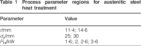
In the experiments all specimens were welded and cooled down to room temperature before the heat treatment was started at a travel speed vht of 5 mm s−1. In each experiment one of the three process parameters (beam radius r, beam power Pht and transversal distance between heat treatment and weld dy) was varied following Table 1.
Process parameter regions for austenitic steel heat treatment
Following on from the results of direct irradiation of the weld zone while the beam is deflected at a speed of 1000 mm s−1 to the other side of the weld, a second experimental series was conducted for non-quasi-simultaneous heat treatment with r = 14·6 mm, dy = 30 mm and vht = 5 mm s−1 using a conventional laser welding optics and 10 mm thick S355J2+N steel plates (welded with a beam power of 9 kW and a speed of 33·3 mm s−1). This conventional laser beam welding optics does not provide beam scanning. Therefore, heat treatment of each side was performed in single work steps. In the first step the defocused beam travelled parallel to one side of the weld and in the second step the other side was heat treated. As a result of this treatment in two steps, lesser weld reheating and larger weld stress reduction was expected.
In this second experimental series of heat treatment with defocused laser beam using a conventional laser welding optics, the radius of 14·6 mm was justified based on beam power density measurements and variation of the distance between the optics and the specimen level. A travel speed of 5 mm s−1 and a transversal distance of 30 mm between the weld and the heat treatment centre were used in these experiments. In each experiment a different beam power (2, 3 and 3·5 kW) was utilised for the heat treatment.
As a practice linked example, some experiments with non-quasi-simultaneous heat treatment of a transmission shaft made of case hardening steel 23MnCrMo5 E joined to two components made of ferritic steel StW24 W were conducted in a third test series.
In these experiments, the conventional laser beam welding optics and a laser beam radius of 7 mm were used for heat treatment of the area next to the axial and the segmented radial circumferential welds, as illustrated in Fig. 3. The heat treatment was performed in a transversal distance of 18 mm to the welds at a travel speed of 5 mm s−1 and with 1·75 kW beam power.
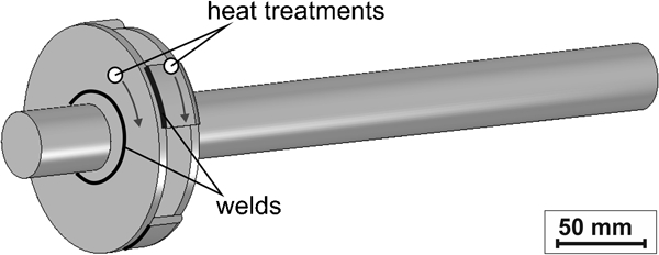
Heat treatment process scheme for experiments with transmission component
After the experiments, the residual stresses were measured using Cr Kα X-ray diffraction at the specimen surfaces with a collimated beam diameter of 1 mm (averaged over the X-ray penetration depth of a few micrometres). In the measurements a cathode current of 7 mA and a voltage of 30 kV were used. The stresses were calculated adopting the sin2 ψ method with cross-correlation. The results revealed stresses with measurement errors of ∼50 MPa.
Results and discussion
For the ferritic steel S355J2+N in Ref. 18 the temperature region which revealed the largest yield stress reduction during heating was ∼700°C. In the first experimental series with the austenitic steel X8CrMnNi19–6–3 the generated temperatures were different. During these linear beads on plate welding experiments, longitudinal bulging of the weld was observed due to the larger heat generation on the top surface compared to the bottom surface. This phenomenon was also found in the experiments with the ferritic steel in Ref. 18. Because of the smaller material thickness and the different coefficients of thermal expansion of the austenitic plates (only 3·8 mm thick) these deformations occurred in larger dimensions compared to the ferritic ones. In order to minimise distortions, temperatures of ∼500°C were generated in most experiments. With a beam power of 2 kW, a beam radius of 11·4 mm and a welding speed of 5 mm s−1, maximum temperatures of ∼500°C were produced in the heat treated regions. Beam power of 2·6 kW and beam radius of 14·6 mm offer the same temperature region at the same travel speed. The results in Fig. 4 show that with larger beam radii the stress reduction in the weld of this austenitic material was increased considerably.
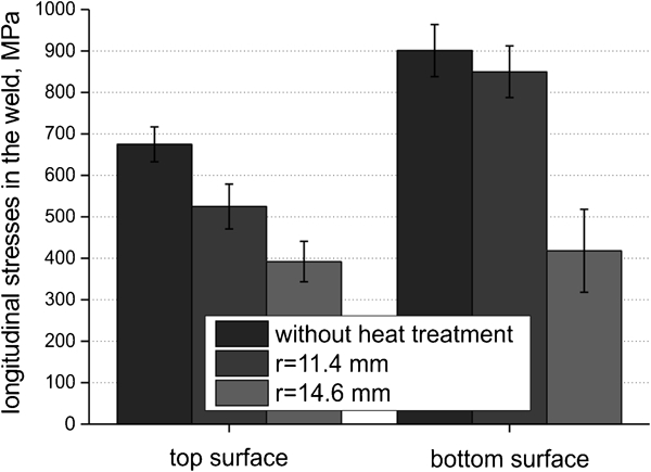
Influence of beam radius r for heat treatment with defocused laser beam (r = 11·4 mm and Pht = 2 kW, r = 14·6 mm and Pht = 2·6 kW, Tht,max≈500°C, vht = 5 mm s−1) on longitudinal stress reduction on weld surfaces of austenitic steel specimens
As concluded from the experiments with the ferritic steel, the higher the beam power Pht was chosen for the heat treatment, the larger was the difference between the stress reduction on the bottom and on the top surface of the weld. In comparison to the stress reductions in the austenitic steel for different beam powers, these differences between the stresses on the top and on the bottom surfaces are smaller than those in the ferritic steel, as depicted in Fig. 5. The reason is the lower generated temperature of ∼500°C during heat treatment. In the experiment with 3·6 kW, ∼700°C was generated on the top surface of the austenitic specimen. For this weld a longitudinal weld stress ratio of 10∶1 was received between the top and bottom surface. The most qualified transversal heat treatment distance was seen in a similar value to that concluded from the experiments with S355J2+N. Here the largest stress reductions were received at distances in a range of about the used defocused beam radius plus 12–15 mm.
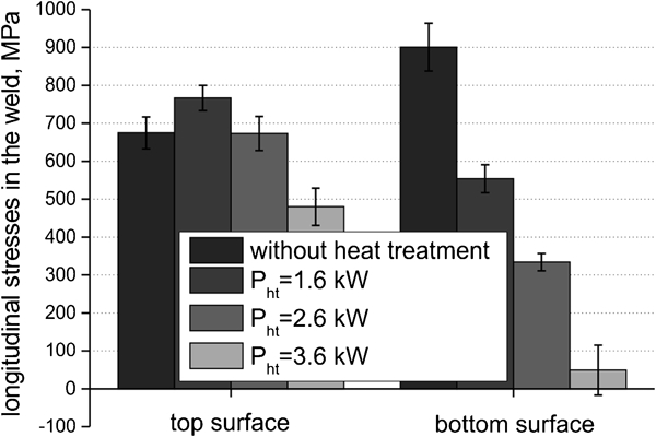
Influence of beam power Pht for heat treatment with defocused laser beam (r = 14·6 mm, dy = 25 mm, vht = 5 mm s−1) on longitudinal stress reduction on weld surfaces of austenitic steel specimens
In Fig. 6 the longitudinal stress profiles perpendicular to the weld of a welded austenitic specimen are compared with the stress profiles of a welded and heat treated specimen showing the best experimental results and low distortions. In the heat treated specimen the longitudinal stresses on the top surface of the weld were reduced by >37% and on the bottom surface by >16%.
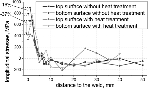
Longitudinal stress profiles on top and bottom surfaces of welded austenitic steel plate compared with longitudinal stress profiles of welded and heat treated specimen (r = 14·6 mm, Pht = 2·6 kW, Tht,max≈500°C, dy = 30 mm, vht = 5 mm s−1)
For ferritic and austenic steels high weld stress reductions were received. However, due to the slow beam deflection frequencies of only 2 Hz 20–30% of the beam, energy is absorbed by the material in the weld zone during the beam deflection from one side of the weld to the other side in the quasi-simultaneous heat treatment. This partial energy leads to enhanced weld zone reheating. Direct weld zone heating by the laser beam was believed to be avoided by conducting the heat treatment of each specimen side in two sequent separate sub steps. From such procedure, higher stress reductions were expected as well. Respective heat treatment experiments were performed in two other experimental series in two steps with the ferritic material using the conventional laser welding optics.
In the second series some experiments with specimens made of the ferritic steel S355J2+N with 10 mm material thickness were conducted to check if this procedure also works for larger thicknesses. In Fig. 7 the longitudinal weld stress reductions for different beam powers after heat treatment are compared to the weld stresses after welding without post-welding heat treatment. With 2 kW beam power a temperature of 680°C was generated on the specimen top surface during the heat treatment. On the bottom surface only 270°C were produced. This demonstrates that the compressive effect for the intermediate material between the weld and the treated regions is low which results in low stress reduction. In addition, at these low temperatures no measurable distortion was found. With this high material thickness a larger heat quantity had to be used to generate the needed 700°C averaged over the whole material thickness. Higher beam powers lead to temperatures higher than 700°C on the top surface and provide the stress reducing effect of this method for the bottom surface. For example, with a beam power of 3 kW the temperature of ∼1090°C was produced on the specimen top surface and nearly 380°C on the bottom surface. With this power the stresses on both surfaces were reduced from 600 to ∼200 MPa. With 3·5 kW the reduction on the bottom surface could be increased by ∼100 MPa compared to the specimen which was treated with 3 kW beam power. In this case, temperatures of 1290 and 420°C were generated on the surfaces. In all three specimens the distortions were approximately zero.
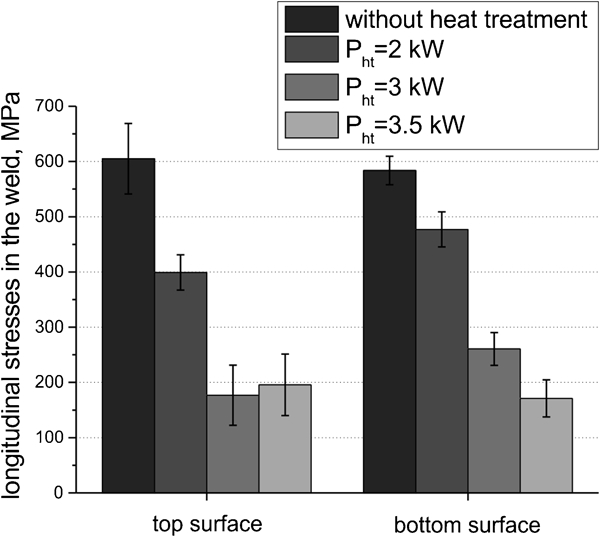
Influence of beam power Pht for heat treatment with defocused laser beam (r = 14·6 mm, dy = 30 mm, vht = 5 mm s−1) on longitudinal stress reduction on weld surfaces of 10 mm thick S355J2+N specimens
For the most suitable transversal distance and travel speed of the heat treatment similar results were received in these experiments compared to those of the experiments with thinner materials. Accordingly, this method for welding residual stress reduction is also adaptive to up to 10 mm thick beam welds.
Finally in the third series of experiments the heat treatment with a 7 mm beam radius was performed at the transmission component. Averaged longitudinal tensile stresses of ∼170 MPa were measured after welding in the axial circumferential welds. After heat treatment these stresses were reduced to compressive stresses of ∼170 MPa. A similar stress reduction of ∼340 MPa was achieved in the segmented radial circumferential welds. Before heat treatment longitudinal tensile stresses of 340 MPa were measured in these welds. Owing to the heat treatment these stresses were mitigated to ∼0 MPa. Transverse stresses in both weld types were affected to a minor degree. The measured transverse stresses were compressive stresses in the range of 150–200 MPa after welding. Owing to the heat treatment they were decreased to 60–90 MPa of compressive stresses.
This practice linked example verifies that this stress mitigating procedure provides a qualified tool for longitudinal stress mitigation in beam welds in complex components and weld geometries by drawing on the recommendations for the process parameter values which were reasoned in Ref. 17. As concerns the temperature the experimental results for the austenitic steel upgrade these recommendations by the fact that the most suitable temperature region to be generated in the heat treated zones depends on the temperature dependent material properties.
Conclusions
In the presented experimental results the high longitudinal residual stresses in beam welds were mitigated by application of a defocused laser beam travelling in a specific distance parallel to the weld and heating this material region up to several hundreds of degrees Celsius. These new results received in the three experimental series using different materials, different material thicknesses and especially complex weld and component geometries qualify this procedure for longitudinal stress reduction in laser beam welds in different applications. In addition, these research findings show that non-quasi-simultaneous heat treatment of each side beside the weld leads to similar stress reductions in the weld.
This means that heat treatment with conventional laser welding optics which does not enable quasi-simultaneous heat treatment of both sides beside the weld also attains high stress reductions in the weld.
Furthermore, this procedure is applicable to larger material thicknesses up to 10 mm. By adhering to the following recommendations the highest stress reductions can be expected.
For thin materials, temperatures have to be produced in a region showing large reduction in yield strength while heating.
For thicker materials, higher temperatures on the top surface can be generated to extend the depth effect of this procedure.
The beam radii should be as large as possible (limited by the experimental set-up).
The travel speed should be as low as possible.
Transversal distances of around the radius plus 10–15 mm have to be used.
Footnotes
Acknowledgements
The authors would like to thank the German Federation of Industrial Research Associations (AiF) and the German Federal Ministry for Economics and Technology (BMWi), for making this research possible by funding the Project 16139 N ‘Anwendung der Mehrstrahltechnik zur Reduzierung der Eigenspannungen bei EB- und LB-geschweißten Bauteilen’ (‘Application of the multiple-beam-technique for residual stress reduction in EB and LB welded components’). In addition the authors would like to thank the TRUMPF GmbH+Co. KG for providing their laser scanner optics for this research.