
Abstract
The formation of large residual stresses continues to be a problematic side effect of all common welding processes. In this work, localised high pressure rolling of gas metal arc welds to relieve these residual stresses has been investigated using strain gauging and neutron diffraction. Rolling was found to remove undesirable tensile stresses and even induce large compressive ones, though only when applied after rather than during welding. Strain measurements taken during combined welding and rolling operations show that this is because material at the weld line continues to yield as it cools. This erases any beneficial effect on the stress distribution of rolling at high temperature. A method of rolling using an oscillating force is also presented and found to be just as effective as the equivalent static force process.
Introduction
Most welding processes use rapid heat input at the material interface to briefly achieve a temperature sufficient for bonding to occur.1 As the material cools, thermal contraction occurs, and the mismatch between the thermal strain experienced by material at the weld line and that in the surrounding regions causes large residual stresses. In the case of a linear weld, such stresses are characterised by a large tensile peak in the longitudinal direction of the weld at the weld line and balancing compressive longitudinal stresses elsewhere. Residual stresses of this type are generally considered very undesirable: tensile stresses at the weld seam can accelerate fracture-based failure mechanisms, such as fatigue,2 and cause physical distortion of the completed object, which often requires costly correction.3
To relieve or prevent the tensile stresses that form at the weld line, an expansion strain must be provided at some point in the process. Current methods that work on this principle include ultrasonic impact treatment and shot peening, which can be applied post-weld to cause localised yielding at the surface of the material. However, these are only able to cause material plasticity, and hence a beneficial change in the residual stress state, to a relatively small depth into the material, typically in the order of 1 mm for structural steels.4 In thicker material, residual stresses induced by such methods are usually in equilibrium over the material's thickness rather than causing the whole weld region to be stress relieved. Therefore, while this has a beneficial effect on fatigue crack resistance at the weld surface where such treatment is applied, it is an imperfect method for distortion reduction.
High pressure rolling of the weld line is one process that has been suggested as an alternative to peening. Applying a large compressive force in the direction normal to the welded object's surface causes plastic expansion in the in-plane directions.5 Rolling is able to achieve much larger strains to a much greater depth and is simple to apply. The process may be carried out during welding, directly behind the welding heat source (here termed in situ rolling), or applied to a fully completed weld (post-weld rolling). Initial investigations into the effect of localised rolling of weld seams were carried out by Kurkin et al. in the 1980s.6, 7 However, only recently has the process been re-examined: an experimental study by Altenkirch et al. 5 showed the dramatic effect of this method on stresses in friction stir welds, while Wen et al., 8 Sun et al. 9 and Yang and Dong10 demonstrated the effectiveness of the technique using finite element analysis. Altenkirch et al. 5 and Wen et al. 8 have indicated that post-weld rolling is far more effective at reducing residual stresses than rolling in situ; however, the reason for this is not currently known.
Rolling of the weld seam requires the application of a large force to a small area. Supporting this force means that the machine used for rolling must be of relatively heavy construction. To reduce the load on the rolling machine structure, a method of rolling using a dynamic force applied by an oscillating mass has been proposed here. In the following experiments, the effects of in situ and post-weld rolling using a constant force on residual stress formation have been assessed. Rolling using dynamic force is also demonstrated and compared with the equivalent constant force process.
Experimental
Welded specimens
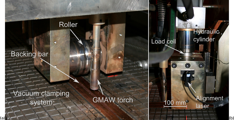
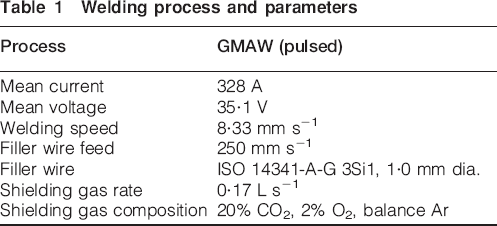
Rectangular plates of hot rolled S355JR structural steel, with overall dimensions 750×300×6 mm, were used for the experiments. The yield stress of this material was ∼474 MPa. For each specimen, a linear single pass bead-on-plate weld, 600 mm long, was made using gas metal arc welding (GMAW) with the parameters shown in Table 1. This set of parameters was chosen so as to just achieve full penetration of the weld through the plate thickness. During welding, the plates were held flat by a vacuum clamping system: this applied an even suction to the entire underside of each specimen, except for a region directly underneath the weld line, 48 mm in width, where a copper backing bar was used (see Fig. 1a). The clamping was maintained for 600 s after completion of the weld, or in the case of specimens treated with post-weld rolling, 600 s plus the duration of the rolling operation (∼72 s). Preliminary experiments showed that after this time, the temperature distribution in the welded specimens had fully equilibrated and was ∼30°C throughout the specimen.
Apparatus for localised rolling of weld seam
Welding process and parameters
Rolling
Both in situ and post-weld rolling with a constant force and post-weld rolling with a dynamic force were investigated in this study. Figure 1 shows the apparatus used for weld seam rolling: this machine is capable of rolling using a constant force or applying a time-varying force using an oscillating mass in the manner described in the section below. A hydraulic cylinder applies a vertical force through a single roller supported in a fork assembly. When rolling with a constant force, the force is set directly by changing the cylinder pressure. In dynamic force mode, the loading cycle is a function of several parameters, including the cylinder pressure, oscillating mass and hydraulic valve timings. The applied force is monitored at a frequency of 500 Hz by a ring type load cell installed between the end of the hydraulic cylinder shaft and the upper part of the roller fork (see Fig. 1b).
To carry out the welding and/or rolling operation, the workpiece remains static, while the crossbeam, with the roller head and welding torch attached, is translated by a linear drive system. The machine applies no torque to the roller, which is left free to rotate as it moves over the workpiece. The roller used here (see Fig. 1a) was of 100 mm diameter and 30 mm axial width and made from hardened BS 4659 BH13 tool steel. A shallow groove around the circumference of the roller was used to accommodate the weld seam. Figure 2 shows a comparison of the roller groove with the mean profile along the length of an unrolled weld, taken from laser coordinate measurements. Visible plastic deformation of the weld seam occurs during rolling at higher loads, and the roller groove acts to contain the deforming material, producing a lower, wider weld seam. Under all rolling conditions, the roller acts only on the top of the weld seam (∼12 mm in width) and does not come into contact with the plate surface at either side.
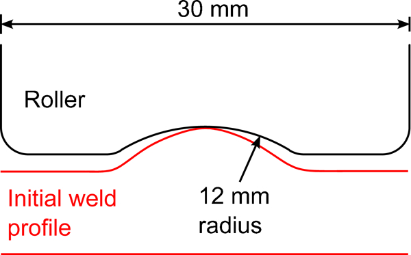
Contoured roller to accommodate weld seam
Specimens were produced without rolling, with in situ rolling at static loads of 25, 50 and 100 kN, and with post-weld rolling at static loads of 25, 50, 100 and 150 kN. Post-weld rolling with a dynamic load was used to produce a single additional specimen. The parameters used for this were designed to produce a peak applied force of 50 kN using an oscillating mass of 1500 kg and an oscillation frequency of ∼3·8 Hz.
For in situ rolling, the GMAW torch was positioned 100 mm in front of the roller axis (as shown in Fig. 1b), and rolling took place as the weld was carried out. Since the travel speed used for welding was 8·33 mm s−1, the centre of the roller passed over the weld metal ∼12 s after it was deposited. A finite element model of the welding process, calibrated using prior experimental temperature measurements, predicted the temperature here to be 890°C. The same travel speed (8·33 mm s−1) was also used for post-weld rolling, in which case the cross-beam was returned to the start position once the weld was complete, ready to carry out the rolling operation after 600 s. For all specimens, only one welding and one rolling pass was used.
Application of dynamic load
A system for rolling by applying a time-varying force using an oscillating mass is shown Fig. 3. The hydraulic cylinder used to apply the rolling force, instead of being attached directly to the cross-beam, is coupled to a large mass that is allowed to move freely in the vertical direction. With the roller in contact with the workpiece, rapidly extending the cylinder causes the mass to accelerate upwards. This acceleration causes a peak force:

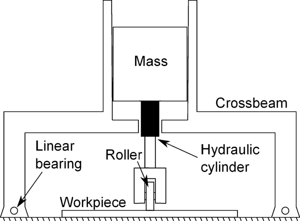
Dynamic load rolling mechanism with accelerated mass
Transient strain measurement
Strain gauges were used to investigate the differences in residual stress development during post-weld and in situ rolling: a comparison was made between the two techniques operating with a static load of 50 kN. The locations where strain measurements were taken are shown in Fig. 4. Elevated temperature Ni–Cr metal foil gauges (Micro Measurements WK series) were used at 20, 30, 40 and 50 mm from the weld centreline, while standard types were used elsewhere. Rosette gauges were used to simultaneously measure strain in three in-plane directions and hence to determine the principal strains. However, due to the limited number of measurement channels available, it was only possible to attach four rosettes and four uniaxial gauges per specimen. Consequently, two specimens were required for each of the in situ and post-weld rolling conditions: between them, each pair of specimens had a rosette positioned at every measurement location. Individual three-wire quarter bridge circuits were used for each strain gauge, and the measurements were logged at a frequency of 2 Hz using a National Instruments DAQ-mx modular data acquisition unit. Thermocouples were also used to measure the temperature at each strain gauge location in Fig. 4.
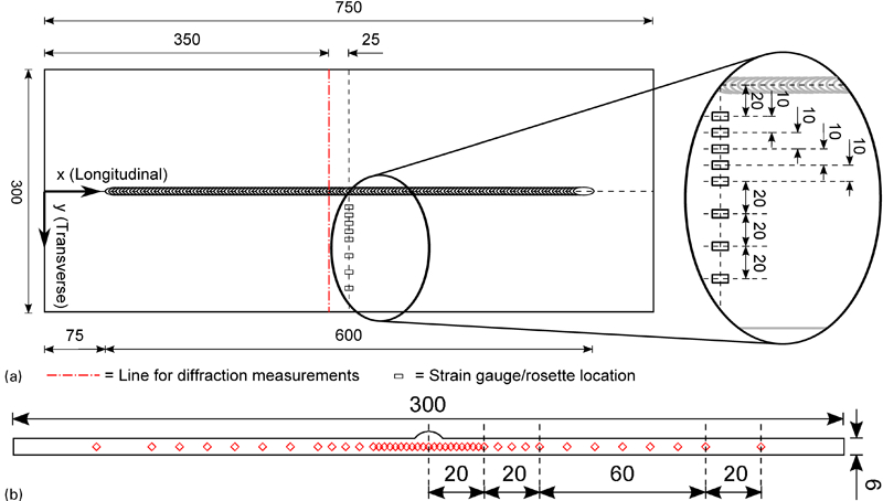
Measurement locations on welded specimens
The total state of strain ϵ in any material may be decomposed into strain contributions due to elastic deformation ϵ

Residual strain measurement
Neutron diffraction may be used to measure interatomic spacings in polycrystalline materials, and from this infer residual elastic strains, from which residual stresses can be calculated. The process of residual stress measurement using this technique is described in detail elsewhere.13, 14 For this experiment, measurements were carried out using the SALSA monochromatic neutron strain diffractometer at the Institut Laue-Langevin, Grenoble, France.15 Residual elastic strains were measured at 43 locations on a transverse line close to the mid length of each specimen, as shown in Fig. 4. (For the specimen rolled post-weld at 25 kN load, measurements were instead taken every 2 mm all the way across the section to 130 mm from the weld line. This can be seen in Fig. 5 a and c.) Lattice spacing in the longitudinal x, transverse y and normal z directions was measured at each point; cuboid gauge volumes of 2×2×2 mm were used for measurement in the longitudinal direction, and 2×20×2 mm for the transverse and normal directions. The ferrite {211} plane was used for all of the measurements, since this plane has a low sensitivity to intergranular strains, and is therefore well representative of strain in the bulk material.16, 17 A neutron wavelength of 1·644 Å was used, giving a scattering angle (2θ) close to 90°. All measurements were taken from the nominal mid-plane of the specimen (3 mm depth), and through-wall scans were used to accurately position the gauge volume in the through-thickness direction. Reference measurements of the unstressed lattice parameter were taken from unstressed comb samples cut from nominally identical plate specimens in the manner recently discussed by Withers et al. 18 and Altenkirch et al. 19 To account for the effect of the varying degree of plastic deformation on the single diffraction peak position used, different reference specimens were used for different rolling loads.
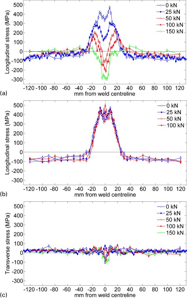
Comparison of residual stress distributions for different roller loads: longitudinal stress after a post-weld and b in situ rolling and c transverse stress after post-weld rolling
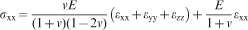
Residual stresses were determined from the strains by assuming isotropic elastic properties and a general triaxial stress state20
Results
Residual stress due to in situ and post-weld rolling
Longitudinal residual stress distributions resulting from rolling under various loads are shown in Fig. 5a and b. For post-weld rolling (Fig. 5a), a continuous decrease is observed at the weld line for increasing values of load, accompanied by a broadening of the region of induced compressive stresses. By contrast, in situ rolling (Fig. 5b) has essentially no effect on the residual stress distribution, regardless of the force applied.
Transverse residual stresses after post-weld rolling are shown in Fig. 5c but do not exceed ±100 MPa anywhere on the specimens. Post-weld rolling at high loads (100 and 150 kN) gives a small region of compressive transverse stress at the weld centreline. However, the most important point to note is that the process produces no significant tensile residual stresses in the transverse direction, which could have a detrimental effect on fatigue performance. Owing to the necessity of stress equilibrium, this result only represents the cross-section over which these stresses were measured: it is expected that there would be a corresponding tensile state of transverse stress elsewhere along the weld line.
Transient behaviour
Analysis of the strain gauge measurements was used to find the transient biaxial state of stress during the welding and rolling operations. The longitudinal stress component is shown in Fig. 6a and b. Data are given only up to a minimum of 40 mm from the weld line, since in the case of both in situ and post-weld rolling specimens, the strain rosettes at 20 and 30 mm from the weld line were affected by material plasticity and radiant heat from the welding arc, rendering the data invalid. The general form of stress distribution during welding and cooling (i.e. up to ∼600 s) is very similar regardless of whether in situ rolling is used. This characteristic distribution of stress is generated by the changing distribution of temperature, and the consequent pattern of thermal dilation and deformation, during the welding process. This was discussed in greater detail in a previous paper.12
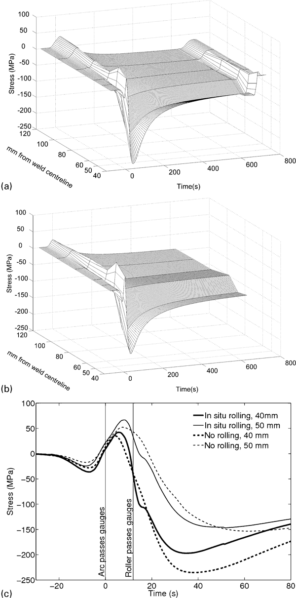
Longitudinal stress during a welding with post-weld rolling and b welding with in situ rolling and c magnified view of stresses at 40 and 50 mm from centreline during welding: in all cases, 0 s is defined as when welding arc passes line of strain gauges
The effect of post-weld rolling is visible in Fig. 6a at ∼672 s. The modest compressive residual stresses that exist here after cooling are reduced almost to zero. For equilibrium, the distribution of longitudinal stress must sum to zero over the transverse section. Therefore, this reduction in compressive stress indicates that the corresponding tensile stresses in the weld region must also be reduced, as is also seen in the longitudinal residual stress profiles in Fig. 5a. Finally, another important aspect of Fig. 6a and b is that they show that the stress distribution continues to develop significantly for at least 300 s after the arc passes. Since the contraction of material at the weld line is more rapid than that of the surrounding area, this suggests that the weld line material yields continuously over this period.
Figure 6c shows a magnified view of the stresses at 40 and 50 mm during and immediately after welding (which takes place from −36 to +36 s). In situ rolling can be seen to affect the transient development of stress: the longitudinal plastic strain provided by rolling at the weld line means that thermal contraction of the material there does not cause such great stresses in the surrounding material, and so the maximum compressive stresses seen for the case of in situ rolling are slightly lower. However, during cooling, the longitudinal stresses settle to roughly the same values as for the unrolled specimens. By contrast, no further cooling occurs after post-weld rolling (Fig. 6a), and so its effect is permanent.
Dynamic loading
The force applied during post-weld dynamic load rolling over a 1 s interval can be seen in Fig. 7a. Although the mass oscillates at a frequency of 3·8 Hz, the figure indicates that there are additional higher frequency variations in the applied force. These are probably related to the natural oscillation frequencies of the system that comprises the mass and compliance of the hydraulic cylinder and roller fork. Together, the roller travel speed (8·33 ms−1) and the oscillation frequency (3·8 Hz) imply that a complete oscillation cycle occurs for every 2·2 mm of weld length. The measured residual stress distribution from this type of loading (shown in Fig. 7b) is very similar in both magnitude and distribution to the one caused by rolling with a constant load of 50 kN.
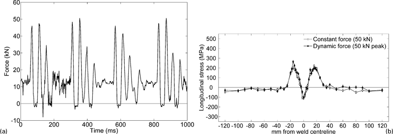
a time varying force applied during dynamic load rolling and b comparison of residual stress distributions resulting from constant and dynamic load rolling
Discussion
Stress field development during in situ and post-weld rolling
As can be seen from Fig. 5a, plastic deformation at the weld line from post-weld rolling can provide the elongation required to relieve tensile residual stresses. Furthermore, this elongation can be sufficient to produce significant compressive residual stresses. This is in agreement with the modification of the residual stress field previously observed by Kurkin and Anufriev7 and Altenkirch et al. 5
While post-weld rolling can completely invert the distribution of residual stress in the weld, in situ rolling (Fig. 5b) has a negligible effect. The measurements of transient stress shown in Fig. 6 suggest the reason for this: the magnitude of the thermal contraction strain that occurs in the material at the weld line during cooling is much larger than any residual elastic strain that can be supplied by in situ rolling, since the latter is limited by the yield strain of the material. Furthermore, significant thermal contraction continues for a long time (∼300 s) as the material cools. Therefore, any positive strain supplied by in situ rolling is irrelevant, since this would be caused anyway by yielding due to thermal contraction during cooling. On the other hand, no further cooling occurs after post-weld rolling, so no subsequent yielding of the rolled region takes place, and therefore, the mechanically-induced strain remains.
A rough approximation of the contraction strain encountered during cooling can be calculated using the material's coefficient of thermal expansion (∼1·217×10−5 K−1 at ambient temperature) and the temperature during in situ rolling (890°C, from finite element predictions). Neglecting the effects of microstructural change, this indicates a thermal contraction of around −1·06% during cooling from the in situ rolling temperature to room temperature. Since the maximum effective strain that can be provided by rolling is limited by the yield strain of the material (∼0·2%), the effect of thermal contraction will dominate the final stress field. An important consequence of this is that any mechanical process, such as rolling or peening, which is applied exclusively at high temperature to the mechanically constrained material of a weld, will be ineffective at relieving residual stresses. Such processes instead must be applied at a temperature low enough to avoid subsequent gross plasticity.
Although post-weld rolling was applied successfully here to structural steel and has previously been used on 2000-series aluminium alloy,5 the relatively large deformations resulting from it might cause cracking in less ductile materials. If necessary, in situ rolling at an intermediate temperature (much lower than used here) might be used instead, but this would come at the cost of decreased stress reduction effectiveness compared with post-weld rolling. In situ rolling also has potential applications other than residual stress control. For example, it could be used to forge the weld seam; smoothing it to remove geometric stress concentrations or to give it a different cross-sectional profile. This might be used to improve the weld's fatigue performance or its appearance, for example. The effects of this type of rolling on microstructure and mechanical properties are currently being evaluated.
Load requirement for residual stress relief
Larger rolling loads cause a higher degree of plastic deformation and therefore have a greater effect on the residual stress distribution, as shown in Fig. 5. In addition to the greater magnitude of the induced compressive stresses, the region of compressive stress broadens with increasing roller force, an observation predicted in a recent modelling study by Wen et al. 8 Despite being applied only to the top of the weld seam, which has a width of ∼12 mm, rolling at higher loads causes yielding over a much wider area. Moreover, since the neutron diffraction measurements were taken from the nominal mid-thickness of the 6 mm thick specimen plates, and large compressive stresses are observed there after post-weld rolling, it is probable that rolling causes plasticity throughout the plate's thickness. However, at some point, there must be a practical upper limit to the thickness of welds that can be treated in this way.
Although dynamic-load rolling was only carried out using a single value of peak force (50 kN), the residual stress distribution that resulted from this is almost identical to the corresponding distribution for static-load rolling at the same force (see Fig. 7b). The process therefore seems not to be detrimentally affected by the time-varying nature of load application in dynamic-load rolling.
Conclusions
In this work, we have demonstrated the following.
High pressure post-weld rolling of weld seams can give a dramatic reduction in the tensile longitudinal residual stresses normally encountered at the weld line. By using higher values of rolling load, large compressive stresses may be created in and around the weld.
The region over which compressive residual stresses are induced by post-weld rolling can be much wider than the area of contact that the roller has with the weld bead surface.
Rolling of the weld seam at high temperature as it is welded is ineffective at reducing residual stresses due to the subsequent yielding of material in the weld region as it cools. For the same reason, any other mechanical process applied exclusively to the weld region at high temperature as a weld is carried out will be similarly ineffective.
A dynamic roller force, rather than a constant one, can be used to give the same effect on the residual stress distribution in a weld. This reduces the structural requirements of the rolling machine.
Footnotes
Acknowledgements
The authors acknowledge beamtime provision from the Institut Laue-Langevin, France, under proposal no. 1-02-68. Funding for this project was provided by Tata Steel Europe and the EPSRC under grant no. EP/G014132/1.