
Abstract
In the oil and gas industry, residual stresses in welded components, such as risers and oil offloading lines, play a key role in determining their fatigue and fracture performance. The focus of this work is on measuring the residual stresses in girth welds of large diameter (508 mm, 20 in. outside diameter) thick walled (25·4 mm, 1 in. wall thickness) pipes. Residual stresses were measured using neutrons on two girth welds on X-65 grade line pipes. One was a carbon steel weld with fully ferritic weld metal, and the second was an Inconel 625 dissimilar weld with fully austenitic weld metal. It was observed that while there were subtle differences, the overall magnitude and distribution of axial and hoop residual stresses were comparable in the two girth welds. These data are consistent with available previous measurements and computer models from the literature.
Introduction
Many of the components in offshore structures, such as oil offloading lines (OOLs) and steel catenary risers, are welded structures. It is well known that weld residual stresses play a critical role in the performance of these structures since it affects properties such as fracture toughness and fatigue resistance.1– 3 In deepwater, components such as OOLs and steel catenary risers are subjected to motions of the floating vessels they are connected to as well as well as vortex induced vibrations, leading to fatigue loading, especially at the hang-off and touchdown areas.2, 3 Recently, it was shown through full scale fatigue testing of X-65 grade line pipes that the fatigue performance of girth welds with nickel based weld metal was superior to that of a carbon steel weld metal.2, 3 One of the major factors affecting fatigue life of welded pipes is residual stresses in girth welds.4 Therefore, it is critical to characterise the residual stresses to both guide fatigue design and to develop mechanistic understanding of fatigue performance.
There is a wealth of literature in the area of residual stresses in welds. These include studies on measuring residual stresses in plates,5– 7 tubes and pipes,8– 12 mitigating residual stresses using jigs13, 14 and weld metal design,15, 16 as well as modelling residual stresses.6, 17– 19 However, there are very little experimental data available on residual stresses in girth welds of thick walled pipes,17– 19 and no work where nominally similar welds with both ferritic and austenitic welds are compared. Therefore, there is a need to measure two-dimensional (2D) residual stress distributions in girth welds of thick walled carbon steel pipes. Neutrons are ideal to map the residual stresses non-destructively, since they can penetrate several millimetres deep into steels and Ni based alloys with reasonable spatial resolution.20
In this paper, comprehensive measurements of residual stresses were conducted on two girth welds on an X-65 line pipe intended for an OOL application.3 A carbon steel weld with a fully ferritic weld metal and an IN625 weld with a fully austenitic weld metal were studied. It was found that the magnitude and distribution of residual stresses are largely comparable in the two girth welds with some key differences. These results are consistent with available published experimental and modelling studies.
Experimental
The pipe material used for this study was an API 5L X-65 line pipe with 508 mm outside diameter (O.D.) and 25·4 mm wall thickness (WT). The chemistry of the X-65 base pipe is provided in Table 1. The girth welds were single sided multipass welds made in the 1G rolled position (Fig. 1) using a pulsed gas metal arc welding process with argon as shielding gas. Both welds used a J bevel design, with 16 passes for the carbon steel weld and 20 passes for the IN625 weld (Fig. 2). Please note that the cap passes were left intact for the carbon steel weld, while it was ground off for the IN625 weld. The carbon steel weld consumable was Thyssen TS-6 ER70S-G, and the IN625 weld consumable was Thyssen Thermanit ERNiCRMo-3. The heat input for both welds was ∼0·77 kJ mm−1. The base metal and weld mechanical properties are reported in Table 1. Additional details of welding can be found in previous work.2, 3
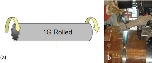
Welding was performed in 1G rolled position
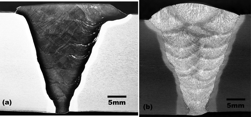
Weld macros
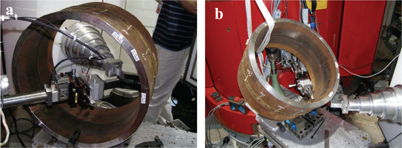
Mechanical properties of base pipe and weld metal*
*Tensile properties were measured according to ASTM-E8 with subsize samples (6·35 mm diameter and 25·4 mm gage length). The weld properties were measured from all weld specimens extracted containing only fill passes.
Chemical composition of X-65 base pipe as provided in mill certificate

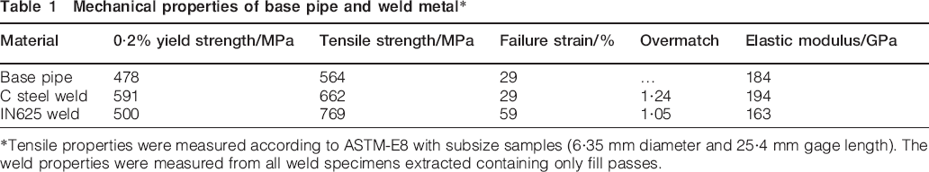
The residual stress measurements were performed in the BT-8 instrument at the National Institute of Standards and Technology Center for Neutron Research (Gaithersburg, MD, USA). Ten inch long pipes with a girth weld in the centre were used for the study. The measured residual strains were converted to stresses following standard analysis techniques.21 Two different sample orientations were used to measure the strains. One orientation was used for axial and radial stresses with a gage volume of 2×2×12 mm (Fig. 3a). For this orientation, the incident neutron wavelength was 1·6718 Å (2Θ≈90·5°). A different orientation with a gage volume of 3×3×3 mm was used for hoop stress measurements (Fig. 3b). This orientation was chosen to minimise absorption losses by decreasing the neutron path through the pipe wall as well as using a shorter wavelength of 1·3577 Å (2Θ≈70·5°). Residual stresses were calculated using different values of d0 for the axial, hoop and radial directions. The values of d0 were measured using toothcomb samples machined out of the weld and base metal. The (211) peak with d = 1·178 Å was used for the carbon steel weld, and the (311) peak with d = 1·085 A was used for the IN625 weld. The measurement grid contained 189 measurements across the cross-section of the girth weld (Fig. 4). Measurements were made at 75° from the seam weld for the carbon steel weld.
Pipe orientations for measurement of three principal residual stress directions
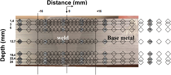
Grid showing overview of measurement locations: measurement locations included weld metal, heat affected zone and base metal (up to distance of 55 mm from weld centreline)
A fundamental underlying principle of neutron diffraction strain measurements is that the grains contributing to a diffraction peak should be uniformly distributed within the gage volume. The IN625 weld metal had very coarse grains (grain size: about 0·5×(1–2) mm). With gage volume sizes of 3×3×3 mm, the large grain size led to sampling of very few or no grains meeting the diffraction condition. Therefore, the grain average had to be improved by oscillating the sample through rotation or translation such that the oscillation does not introduce additional smoothing of the strain gradient to be measured. Therefore, the measurements were averaged for the IN625 weld by acquiring data at equivalent locations along the circumference as well as by rocking the sample in the range of ±5°.
Results
While all three residual stress components (axial, radial and hoop) were measured in this work, only the axial and hoop stresses are reported, as the radial residual stresses were negligible. Please note that for all the data discussed below, the estimated standard deviation is ±20 MPa.
Figure 5 shows the measured residual hoop stresses for the IN625 and carbon steel girth welds. The hoop stresses were tensile in the weld metal throughout the thickness for both welds. They were observed to be mildly tensile (<200 MPa) at the inner diameter (I.D.) and steadily rise to high levels (>400 MPa) near the O.D. In the case of the IN625 weld (Fig. 5a), the stresses were asymmetric about the weld centreline. The highest tensile residual stresses were ∼400 MPa in the weld metal. In the carbon steel weld, the tensile stresses were as high as 600 MPa near the O.D. in the weld metal. In both welds, as one would expect, the base metal had mostly residual compressive hoop stresses being nearly neutral at O.D. and rising to ∼200 MPa at the I.D. These stresses extend throughout the measurement domain to a distance of 55 mm away from the weld centreline.
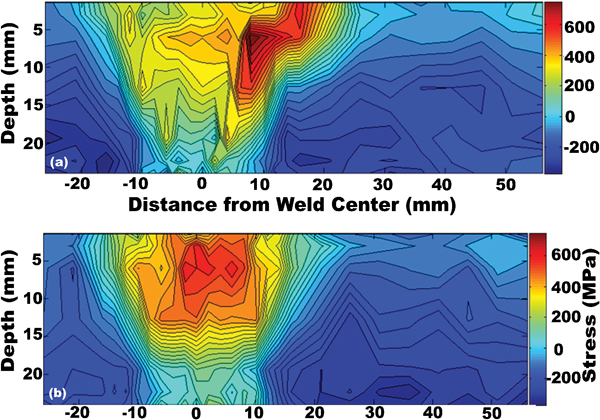
Measured hoop stresses in two girth welds: blue colours indicate compressive stresses, and red colours indicate tensile stresses
Figure 6 shows the axial residual stresses in the two girth welds. It is apparent that in both girth welds, the magnitude of axial residual stresses are about half of the hoop stresses. Another key observation is that for both welds, the axial stresses were asymmetric about the weld centreline. Axial stresses were deeply compressive at the I.D. of the weld and varied through the thickness with highest tensile stresses near the O.D. Specifically, residual stresses at the weld toe were compressive with a magnitude of ∼150 MPa in both welds. However, in the case of the carbon steel weld, they rose to ∼300 MPa just above the weld toe.
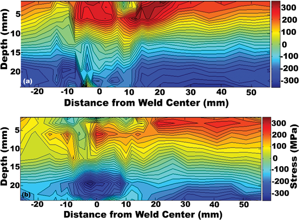
Measured axial stresses in two girth welds: blue colours indicate compressive stresses, and red colours indicate tensile stresses
Discussion
Weld residual stresses are generated due to shrinkage of the weld metal under the constraint of the base metal. The distribution and magnitude of residual stresses are dependent on the physical and mechanical properties of both the weld and the base metals. It also depends on the pipe radius, WT, weld pass sequence and weld metal strength.17, 22
In this work, residual stresses were measured in two girth welds with identical base pipes (r = 254 mm, WT = 25·4 mm, r/t = 10), but with two different weld metals with an austenitic (IN625) and ferritic microstructure. Important differences between the two weld metals are the solidification properties, the mechanical properties and the microstructure. Furthermore, the ferritic weld exhibits a solid state phase transition of γ-Fe to α-Fe at ∼720°C with a volume expansion that can alter the residual stresses that are generated.23 As mentioned in the section on ‘Introduction’, there is a dearth of experiments on residual stresses in girth welds of large diameter, thick walled pipes in general, and it is even rarer to find data on dissimilar welds. Therefore, in this work, wherever possible, the IN625 weld metal results are compared with available studies on austenitic stainless steels.
In butt welds of the kind studied here, the cooling weld bead shrinks around the pipe to impose a force in the hoop direction. This is akin to a tourniquet around the pipe circumference, leading to hoop residual stresses.9 In addition to the full 2D hoop stress distribution shown in Fig. 5, the stresses at the weld centreline are plotted for both welds in Fig. 7. In the literature, many of the experimental and modelling studies on both carbon and stainless weld metals show high tensile residual stresses in the hoop direction, similar to what was observed in this work.12, 17– 19 The stresses were highly tensile in the weld metal near the O.D., decreasing to mildly tensile or compressive in the I.D.9, 17– 19
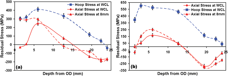
Residual stress profiles along weld centreline (WCL) and 8 mm from WCL: please note that error bars denote one standard deviation
Another observation was that the peak hoop stresses in the weld metal were higher in the carbon steel weld. It is known that the radial shrinkage force is proportional to the pass or weld bead size and the yield strength of the weld metal.17 As noted in the section on ‘Experimental’, the carbon steel weld had 16 passes, and the IN625 weld had 20 passes. While this difference is not insignificant, more importantly, the cap passes were ground off in the case of the IN625 weld, whereas they were left intact in the carbon steel weld (Fig. 2). It is suggested that the presence of the cap passes along with the higher overmatching of the carbon steel weld (Table 1) led to higher hoop stresses near the O.D, whereas the grinding of the cap passes appeared to have relieved the hoop stresses near the O.D. in the IN625 weld. Another subtle difference was the asymmetric tensile hoop stresses in the case of the IN625 weld with high tensile stresses (>600 MPa) in the heat affected zone (HAZ). Based on weld geometry (Fig. 2), it appears that more of cap passes were left intact on the right side of the IN625 weld, leading to the observed asymmetry in the stresses. Furthermore, the tensile stresses in the HAZ of the IN625 weld were higher than expected based on the mechanical properties of the base metal. In some circumstances, the measured residual strains (from changes in lattice spacings) have additional effects included along with the changes due to residual stresses. Measurements in the HAZ can be affected, particularly near the fusion line due to the gage volume containing both ferrite and austenite (IN625) phases as well as changes in lattice spacing due to the intermixing of alloying elements. It is suggested that these difficulties led to the observed higher than expected hoop stresses in the HAZ and need to be studied further.
Based on the axial stresses along the weld centreline shown in Fig. 7, it appears that the residual stresses are of self-equilibrating type in carbon steel weld, while it appears to be of bending type in the IN625 weld.17 The maximum observed axial residual stresses were about half of the maximum observed hoop stresses in both girth welds. The axial stresses varied from being strongly compressive at the I.D. to compressive or mildly tensile at the O.D., with high tensile stresses in between. It is known that the axial stresses are dependent on the pipe radius, WT, weld pass sequence and weld overmatch.17 In thin walled pipes with single sided welds, it has been consistently observed in both experiments and computer modelling that the axial residual stresses are of the bending type, being tensile at I.D. and compressive at O.D.9, 12, 17 However, the axial stresses in thick walled pipes are complex and fluctuate through the thickness, depending on the WT, number of passes, pass sequence and whether the weld is single or double sided.17– 19, 22 With respect to carbon steel girth welds, Scaramangas and Porter Goff12 reported axial residual stresses of self-equilibrating type for a carbon steel girth weld (r/t = 24·1, t = 19·5 mm) with tensile stresses at I.D. and compressive stresses at O.D., which oscillated between compressive and tensile stresses through the thickness. On the other hand, Leggatt10 reported compressive axial residual stresses at the I.D. (r/t = 18·75, t = 16 mm). Consistent with the current work, Yaghi et al. showed that the axial stresses fluctuated through the thickness being compressive at I.D. and O.D. with tensile stresses in the middle in a multipass weld of 55 mm thick P-91 steel pipes.18
In the case of the IN625 girth weld, axial residual stresses appear to be of bending type. Several groups have reported self-equilibrating type axial residual stresses in thick walled stainless steel pipes.19, 22 Yaghi et al. 19 modelled residual stress evolution in thick walled stainless steel pipes (40 mm WT) with various r/t ratios. They predict self-equilibrating type stresses that are compressive at the I.D. and O.D. but oscillating to tensile and compressive stresses through the thickness. It is suggested that self-equilibrating type axial stresses existed in the IN625 weld, but were altered due to the removal of the weld cap. The evidence for this is presented in Fig. 7, showing axial stresses at a distance of 8 mm from the weld centreline. In this location, a significant amount of weld cap is left in the weld (Fig. 2), and the observed stresses are clearly self-equilibrating type.
Finally, in both girth welds, the axial stresses were asymmetric about the weld centreline. It is suggested that the constraints imposed by the previous passes that were made across the weld groove (from say left to right side) on the subsequent passes caused the asymmetry. Yaghi et al. 18 also observed similar asymmetry in residual stresses in a multipass weld of P-91 steel and have shown through modelling that the multiple passes across the weld groove caused such asymmetries.
Conclusions
This work reports one of the first comprehensive 2D measurements of residual stresses in full scale girth welds of thick section pipes. The work will serve as one of the few high quality experimental data that can be used to develop and calibrate finite element models for predicting residual stresses in girth welds. The following specific conclusions are made:
Both carbon steel and IN625 welds exhibited tensile hoop stresses in the weld metal and HAZ and is consistent with literature data.
In both welds, the axial residual stresses were of self-equilibrating type that were complex and fluctuated through the thickness. They were compressive at I.D. and were neutral or mildly compressive at the O.D. of the weld metal with high tensile stresses at the subsurface near O.D. The axial stresses were strongly compressive at the weld toe.
The removal of the weld cap in the IN625 weld led to alteration of residual stresses. This led to asymmetric and high tensile hoop stresses at weld HAZ. The removal of cap passes also led to alteration of axial stresses from self-equilibrating to bending type stresses.
In both welds, the axial stresses were asymmetric, which was attributed to the constraints induced by weld pass sequence across the weld groove.
Footnotes
Acknowledgements
The authors would like to acknowledge the National Institute of Standards and Technology Center for Neutron Research for beam time and support. NT and RA would like to thank D. Lillig, M. D. Crawford, G. Dunn and G. J. Atkins of ExxonMobil Development Company for their support and for providing the welded pipes used in this investigation.
Certain commercial firms and trade names are identified in this report in order to specify aspects of the experimental procedure adequately. Such identification is not intended to imply recommendation or endorsement by the National Institute of Standards and Technology, nor is it intended to imply that the materials or equipment identified are necessarily the best available for the purpose.