
Abstract
In fusion welding, gravity makes a molten metal flow downward and it sometimes causes an irregular shaped weld bead and weld defects such as an undercut. To solve this problem, the authors propose a new electromagnetic controlled molten pool welding process method which controls the molten metal flow by using upward electromagnetic forces, and the applicability of this method to industry is examined. In flat position welding with excessive heat input, the molten metal tends to sag down and an undercut defect is likely to occur. It is found that the upward electromagnetic force given by adjusting the conditions of magnetic field can lift the molten metal up, resulting in the remarkably improved shape of a penetration bead. It is further found that, even in overhead position welding, a well shaped penetration bead without undercuts is obtained by adjusting the welding touch angle as well as magnetic field conditions.
Keywords
Introduction
Gravity makes a molten metal flow downward in arc welding. It results in the occurrence of an irregular shaped weld bead and weld defects such as an undercut and overlap. This problem makes it difficult to conduct high quality and high deposition rate welding, especially in horizontal and overhead positions.
If the molten metal flow and the bead shape are controlled by using electromagnetic force, it is considered to be a promising method for solving this problem. The researches concerning the usage of electromagnetic force have been carried out to improve a behaviour of molten pool.1 They include an arc control method (such as a magnetically impelled arc) and a magnetic stirring method generating electromagnetism torque.2 Since the direction of the electromagnetic force is not in the antigravity direction in these methods, it is difficult to control the bead shape.
To solve this problem, Manabe et al. 3 proposed a basic concept of ‘electromagnetic controlled molten pool welding process (ECMP)’. In this process, the molten metal flow and the bead shape is controlled by using upward electromagnetic force, generated in the molten pool by the magnetic field perpendicular to the unidirectional current. Based on this concept, the ECMP method, in which the magnetic field coaxial to a welding torch is used, has already been put into practical use for thick plate multipass welding in horizontal and vertical positions of a LNG tank with a high deposition rate of 2 to 3 times higher than the past.4, 5
One side welding without a backing is desired for welding a small diameter pipe or a structure in which a welder is unable to enter inside. In conventional backing less one side welding, the shape of the backside of a penetration weld becomes excessively convex downward in flat position welding and an undercut defect in the backside of a weld in overhead position welding. Therefore, the ECMP method is considered very promising because it satisfactorily improves the penetration bead shape which is greatly affected by gravity. However, the previously reported ECMP methods,4, 5 which give the magnetic field coaxially to the welding torch, cannot generate the electromagnetic force in the antigravity direction in overhead and flat position welding but generate the force parallel to the base material surface.
In this paper, the authors propose a new ECMP method which generates electromagnetic force perpendicular to the base material by providing opposed magnetic poles straddling the weld line. They also investigate the influence of various parameters in the new ECMP method on the arc profile and bead shape in flat position welding and the influence of electromagnetic force on arc and bead shape in overhead position welding.
Experimental
Figure 1 schematically shows the experimental apparatus in which the ECMP method is applied to hot wire tungsten inert gas (TIG) welding in flat position. This experimental apparatus consists of a TIG welding torch, a movable wagon (not shown in the figure), a filler wire and a magnetisation coil. A TIG welding power supply and a filler wire heating power supply were installed independently. The TIG torch and filler wire were connected to the negative and positive electrode respectively. The new magnetisation coil is shown in Fig. 2. As for the magnetisation coil, the heat resistant copper wire is wound 500 times around each end of magnetic poles of a mild steel core respectively. In order to acquire the electromagnetic force in the antigravity direction in overhead and flat position welding, it is necessary to give an external magnetic field which is parallel to the welded plate but perpendicular to the welding line (Refer to the section on ‘Concept of ECMP method’). The magnetisation coil is installed in the back side, so that the weld line can be straddled by the coils (see Fig. 1). The base material is an austenitic stainless steel SUS304 of 3 mm thickness and the filler wire is an austenitic stainless steel Y347 of the diameter of 1·2 mm. The behaviour of an arc and a molten pool, and the appearance of a penetration bead are observed by a camera (DPS sensor) equipped with ND filters and band pass filters to take photos in the infrared region. In the case of overhead position welding, the arrangement of the equipment is reversed, i.e. the TIG torch is put backside and the coils are put on the top side.
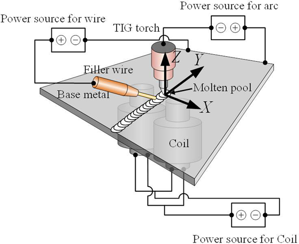
Arrangement of welding apparatus in flat position hot wire TIG
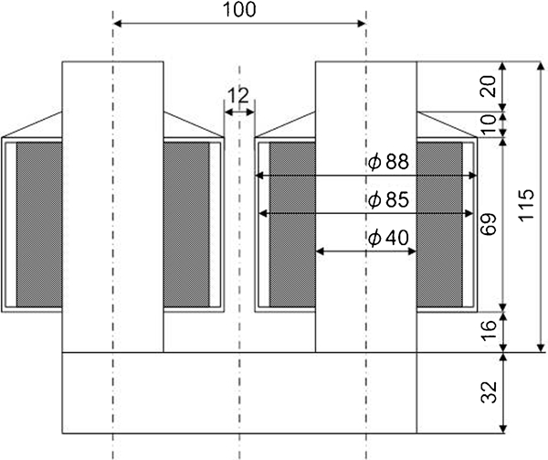
Constitution of magnetic poles
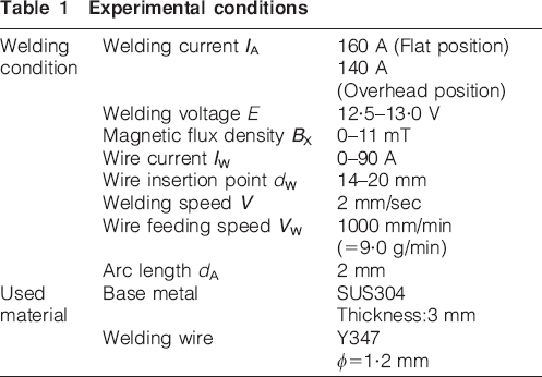
The experiment was conducted under the excessively high heat input conditions in which a molten metal sags down and an undercut occurs. The experimental conditions and the base material used are shown in Table 1. To simplify the experiment, penetration welding was conducted in a bead on plate manner without a groove.
Experimental conditions
Concept of ECMP method
The basic concept of the new ECMP method applied to the flat and overhead position welding is shown in Fig. 3. The unidirectional current, IU (to be mentioned later) is used in the new and previous ECMP methods. However, the direction of external magnetic field in the new method is parallel to the base material and perpendicular to the weld line, unlike the previous method.
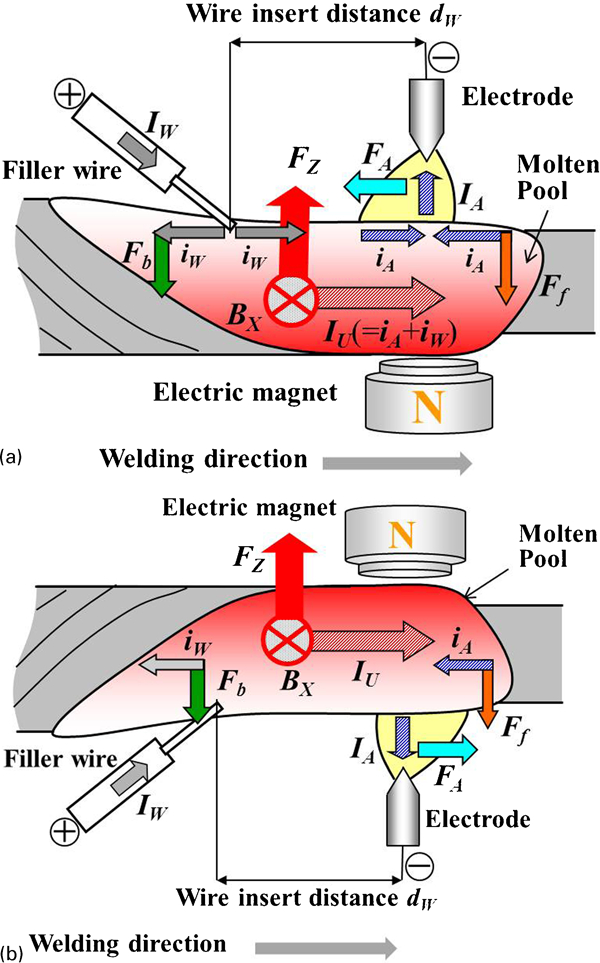
Basic concept of ECMP
In Fig. 3, F, I and BX indicate the electromagnetic force, current flux density and magnetic flux density respectively (⊗: indicates the direction from the front side of this page to the back side). The external magnetic field, BX intersects perpendicularly with the weld line by placing the N and S pole on the opposite sides of the weld line (see Fig. 1). In addition, bold letters in the figure show vector magnitude. By connecting the TIG torch to the negative electrode, and connecting the filler wire to the positive electrode, welding current IA flows in the torch and the wire current IW does in the filer wire. Therefore, elements of arc current iA converge in the molten pool near the TIG torch and elements of wire current iW spread radially in the pool near the wire insertion point. The comparatively strong unidirectional current, IU ( = iA+iW) arises in the welding direction between arc and wire insertion point. It is considered that the interaction between strong current and magnetic field, BX induces the strong upward (antigravity direction) electromagnetic force, FZ( = IU×BX). The current iA flows in front of the torch and iW does behind the wire insertion point in the molten pool. The interaction between these current and magnetic field is considered to initiate the downward electromagnetic forces of Ff and Fb. Moreover, electric current also flows inside the arc. This current interacts with the magnetic field to induce the electromagnetic force FA. This force inclines the arc backward in the welding direction in flat position welding and forward in overhead position welding.
Results and discussion
Magnetic control phenomenon and bead shape in flat position welding
Effect of magnetic flux density
In situ observation of arc and molten pool
The behaviour of the arc and molten pool, and the cross-sectional shapes of beads under varying BX are shown in Fig. 4. The bead sags down between the arc position and wire insertion point at BX = 0 mT (without magnetic field). On the other hand, it is lifted up to 2·5 to 2·7 mm at 11 mT due to the strong upward electromagnetic force FZ induced between the arc and wire. Since wettability between the molten metal and heated wire is excellent, the molten metal sticks to the wire and is lifted up. However, once lifted metal returns to a almost flat shape presumably due to the downward force Fb working behind the wire
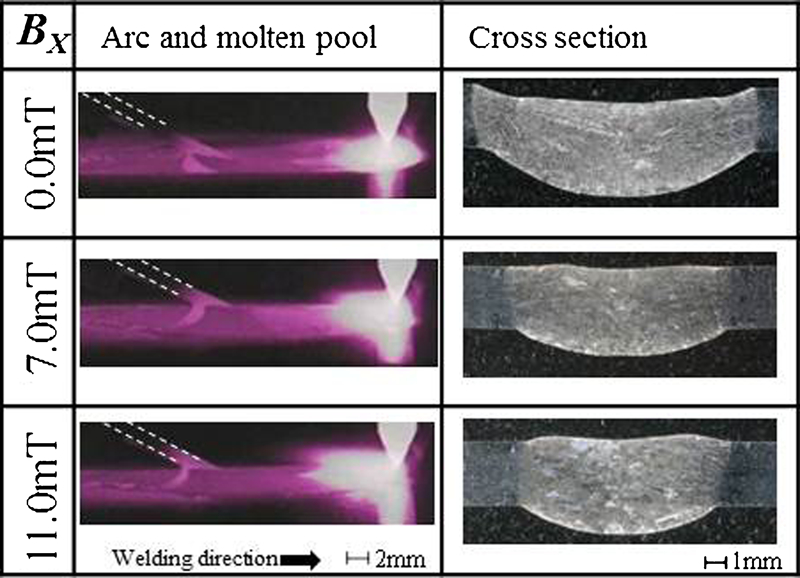
Effect of magnetic flux density on arc profile and bead shape in flat position (IA = 160 A, IW = 90 A, dW = 18 mm)
The arc inclines backward with increasing BX. When BX exceeds 11 mT, the arc excessively inclines backward and heats the wire. Then arcing is likely to occur and unstable welding results. Thus, 11 mT is the upper limit in the present experiment. In addition, the current IA in the arc and IW in the wire induce the magnetic fields around them respectively. These magnetic fields induce the repulsive current force which is considered to control the arc inclination. However, the control of arc inclination is not satisfactory because dW is comparatively long.
Bead shape
A slightly high heat input was used in the experiments because their purpose is to clarify the magnetic control effect. Broad and deep undercut defects are observed on the surface of a bead at BX = 0 mT. The occurrence of undercut decreases with an increase in BX. At BX = 11 mT, a bead with a satisfactory reinforcement is obtained although it slightly dents at the middle region.
Height of bead and deflection angle of arc
The height of bead on the arc side Ha, the height of bead on the back side Hb, and the deflection angle of the arc θ as a function of BX are shown in Fig. 5. Ha increases with an increase in BX, and a bead becomes convex upward. Ha becomes about 0·2 mm at BX = 11 mT. Hb also increases with an increase in BX, and Hb of a bead is improved to about −1·2 mm at BX = 11 mT from the worst −2·2 mm.
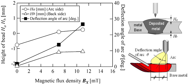
Effect of magnetic flux density on height of bead and deflection angle of arc (IA = 160 A, IW = 90 A, dW = 18 mm)
Moreover, the molten pool is lifted to about 2·5–2·7 mm ahead of the wire according to the observation results. Between the backside of the wire and the trailing edge of the molten pool, the lifted molten pool is pushed down during solidification of metal by the effect of gravity and the downward force in the backside of the wire. Consequently, a satisfactory bead with a convex shape upward was not necessarily obtained. The deflection angle θ of an arc increases with an increase in BX, and the arc is deflected to a maximum value of 27° to the backward direction of the wire.
Effect of wire insertion point
In the foregoing sections the effect of BX, which is a factor of generating an upward electromagnetic force directly, on arc phenomena and a bead formation phenomenon was investigated. On the other hand, when the effect of the lift of a molten pool is taken into account, the acting range of upward and downward electromagnetic forces is considered important. Therefore, the experimental results about the effect of the distance between arc and wire insertion point dW, which governs the electromagnetic force acting range, is described in this section.
Bead shape
Figure 6 shows the cross-sectional shape of a bead at BX = 7·0 mT. When dW is short, the upper side of bead dents downward slightly and the back bead sags down greatly. As for the upper side bead, the dent increases once at dW = 16 mm and decreases with an increase in dW. Then, the bead shape becomes upward convex at dW = 20 mm, conversely. As for the back side bead, an extent of sagging decreases remarkably with an increase in dW, and a sufficient effect of the magnetic control is recognised.
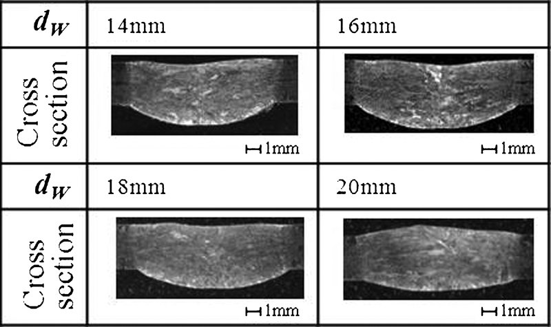
Effect of wire insertion point on bead shape in flat position (IA = 160 A, IW = 90 A, BX = 7·0 mT)
When a wire insertion point is very close to an electrode (dW<14 mm), arcing arises between arc and wire. When the wire is very far from the electrode, the wire tip collides with the penetration bead part where the metal is not sufficiently melted, resulting in unstable welding. Although the effect of lifting a bead is improved as dW increases, dW is limited to 20 mm in the experimental conditions due to the restriction of the size of molten pool.
According to the experimental results, the upward force acting area between arc and wire decreases, and the downward force acting area between wire and the training edge of molten pool increases, as dW decreases. Consequently, it is considered that the molten metal once lifted by the upward force sags down again due to the effects of gravity and downward force. On the other hand, when dW is long, the wire is inserted near the trailing edge of the molten pool. Moreover, it is thought that the molten metal in the backside of wire has relatively high viscosity because of lower temperature, and it becomes difficult for the molten metal to flow. When dW is excessively long, the molten pool almost solidifies at the backside of wire and the effect of downward force is anticipated to reduce. Consequently, the molten metal lifted by the upward electromagnetic force is held as it is, and it is considered that the upward convex bead is obtained. Although dW is not a factor which generates the electromagnetic force directly, dW is considered to be an important parameter which influences a metal flowing process until the lifted molten metal solidifies in the final bead shape.
Figure 7 shows a bead made under the appropriate welding condition. As shown in the figure, it is possible to make flat penetration beads without backings by the new ECMP method. This method is considered to be useful especially for pipe welding because backings are unnecessary, grinding of excessive reinforcements is unnecessary, fatigue strength can be increased, and fluid resistance can be reduced.
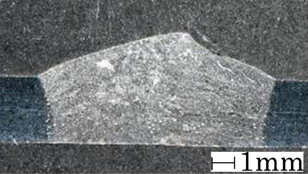
Improved weld bead shape in flat position (IA = 150 A, IW = 90 A, BX = 7 mT, dW = 18 mm)
Magnetic control phenomenon and bead shape in overhead position welding
Effect of magnetic flux density
In situ observation of arc and molten pool
Figure 8 shows the result of in situ observation of overhead position welding using the new ECMP method. Although the molten metal sags down and the wire is buried in the molten metal at BX = 0 mT, it is observed that the molten metal in the backward region of the arc is lifted up with an increase in BX. However, the arc is deflected in the forward direction with an increase in BX, and the molten metal is preceded to the front side of molten pool. The preceded molten metal sags down at BX = 5·8 mT. This precedence is considered to be brought about by two causes: one cause is that the molten metal is blown ahead by the plasma stream of the arc deflected ahead, and the other is that the downward electromagnetic force, Ff is induced ahead of the arc (refer to Fig. 3b). At BX over 5·8 mT, burnthrough occurs. The value of 5·8 mT is thus considered the upper limit in the present experiment. The result of flat position welding experiment shows that a molten metal is well lifted up when dW is long. However, in the case of overhead position welding, the arc inclines ahead and the molten pool is difficult to be formed behind the arc when dW is too long. Therefore, dW was determined to be 5 mm for overhead position welding.
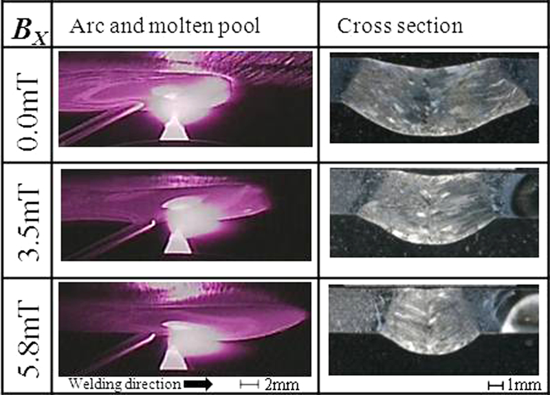
Effect of magnetic flux density on arc profile and bead shape in overhead position (IA = 140 A, IW = 90 A, dW = 5 mm)
In the case of overhead welding, when BX is increased, the molten pool precedes and the downward electromagnetic force Ff works, leading to the occurrence of sagging of molten metal. Even if the ECMP method is used, penetration welding is difficult to conduct unlike flat position welding.
Bead shape
As for the bead shape, at BX = 0 mT, a deep undercut is observed in the back bead. Although the occurrence of undercut decreases with an increase in BX, it dents slightly also at BX = 5·8 mT that is the upper limit. Moreover, the penetration width decreases remarkably with an increase in BX. As BX is increased, the arc deflects ahead and it blows into the sagging molten metal, resulting in a decrease in the melting efficiency of base metal. The decrease in melting rate results in the decrease in penetration width.
Effect of inclining welding torch
In situ observation of arc and molten pool
If the deflection of arc can be suppressed, there is a possibility that the precedence of molten pool is prevented and a proper magnetic control effect is acquired even when BX is increased.
Figure 9 shows the results of the experiment of torch drag angle of 15°. The arc is blowing backward owing to 15° drag angle at BX = 0 mT. The deflection of arc decreases gradually as BX increase and when BX is increased to 7·5 mT, the arc is blowing almost vertically (no deflection). As a result, the molten metal in the back side region of arc is lifted up stably, preventing the precedence of molten pool.
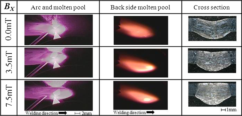
Effect of magnetic flux density on arc profile and bead shape in overhead position (IA = 140 A, IW = 90 A, dW = 5 mm)
On the other hand, the penetration bead shines uniformly in orange in the whole area at BX = 0 mT, and no localised hot area is recognised. At BX = 3·5 mT, a high temperature area in a crescent shape shining in white is recognised at the front edges of molten pool. At BX = 7·5 mT, this high temperature area becomes circular in its shape, and it stays inside a little apart from the front edge of molten pool, being accompanied by a rotational movement. The molten metal heated by arc is forced to flow into the backside by the upward electromagnetic force initiated in the molten pool. This is considered the reason why the high temperature area is formed at the backside of molten pool. At BX = 7·5 mT, the penetration bead length is increased by about 10% as compared with that of BX = 0 mT.
Bead shape
At BX = 0 mT, a deep undercut occurs at the backside of bead. The occurrence of undercut decreases with increasing BX and finally no undercut occurs. At BX = 7·5 mT, the bead becomes slightly upward convex in its shape. BX can be increased to as high as 7·5 mT in 15° torch drag angle welding as compared with the welding of perpendicularly installed torch (0° drag angle). Thus, the satisfactory lift of penetration bead can be acquired.
Conclusions
The new ECMP method was applied to overhead and flat position welding to control the shape of a penetration bead. The results are as follows.
In flat position welding, the effect of lifting a bead is increased with an increase in the magnetic flux density BX. However, arcing occurs owing to the deflection of arc when BX is very high. Arcing is a main cause to limit BX in welding.
Preferable bead shapes are acquired by increasing the distance between arc and wire insertion point dW as long as a filler wire can be inserted stably. Although dW is not a factor which generates the electromagnetic force directly, it is considered to be an important parameter which influences a metal flow process until the lifted molten metal solidifies in the final bead shape.
In overhead welding, an arc is deflected in the forward direction with an increase in BX, and the molten metal is preceded, its amount being increased at the front molten pool. As a result, the molten metal is likely to sag down. The electromagnetic force effect on lifting of molten metal is not sufficient.
On the other hand, when a touch is inclined at 15° drag angle, the arc is deflected and the precedence of molten metal can be suppressed by increasing BX to a level higher than that used in welding of perpendicularly installed torch (0° drag angle). Thus, the strong upward electromagnetic force can be generated. As a result, overhead welding without undercuts and with satisfactory shapes of penetration beads can be realised.
Footnotes
Acknowledgements
The authors are grateful to Dr Tatsushi Haneji of Okinawa Industrial Technology Center, who supported this work. This work was also supported by Grant-in-Aid for Scientific Research (B) No. 15360395.