
Abstract
We reported a new method based on the input electrical impedance of a welding system to measure the resistance of the welding system for the arc power calculation in fusion welding. This impedance can be obtained by dividing the measured voltage to current in their analytic form. Two time recorded waveforms, namely, resistance and reactance of impedance, are therefore calculated. Theoretically, the resistance used for arc power calculation is obtained by dividing measured voltage to current directly without considering the influence of inductance. Through experimental studies, we confirm that the error of arc power calculation incurred by the influence of inductance can range from 2 to 10% depending on the welding voltage and current setting. Since the proposed method can obtain the resistance of the welding system without the influence of inductance, it is a better approach as compared with the current method to obtain the accurate resistance and then arc power.
Background
Fusion welding is an important manufacturing process to join two pieces of material together by heating and melting the material. Theoretically, arc power is the primary factor to determine the total heat input, which is important for modelling the dynamic welding mechanism, stress concentration, weld bead geometry and metallurgical change of weld.1– 3 Therefore, it is crucial to calculate the arc power accurately in order to have rational results of prediction.
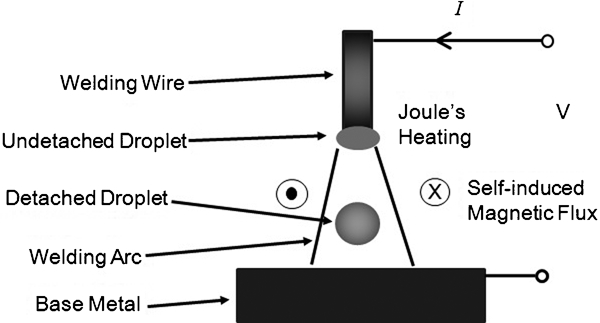
In order to melt the material, electrical power is converted into heat in the welding system, which is governed by Joule's law4

As shown in equation (2), Ohm's law5 is commonly used to obtain the resistance due to the easy measurement of dc welding voltage (V).6,
7 Similar to current measurement, the welding voltage can be measured by a voltage probe being attached to the power terminals. After taking the quotient of welding voltage to current, the resistance is then calculated. Alternatively, Joseph et al.
8 presented the arc power calculation (as shown in equation (3)) by substituting equation (2) into equation (1). Therefore, heat is equal to the arc power


Typical welding system of fusion welding process
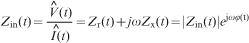
According to Ling et al., 13 the accurate resistance of a welding system without the influence of inductance can be obtained by measuring the input electrical impedance of the welding system such as resistance spot welding. In system modelling, the welding system can be represented by an equivalent circuit consisting of a resistor R, inductor L and capacitor C connected in series. They are naturally the system properties that reflect the welding mechanism of a welding system. By measuring the input electrical impedance of equivalent circuit, the accurate resistance of the welding system can be obtained directly from the real part of input electrical impedance as shown in equations (7) and (8), which will be discussed later.
The objective of this research aims to propose a unique method for accurate resistance measurement and arc power calculation based on the input electrical impedance of a welding system. The method was presented in this paper by introducing the equivalent circuit of the welding system such as flux cored arc welding (FCAW). After that, the error of resistance was revealed by comparing the real part of impedance with the conventional resistance obtained in equation (2). Furthermore, the effect of inaccurate resistance measurement on arc power calculation was then discussed.
Input electrical impedance of welding system
As shown in Fig. 2, a typical welding system such as FCAW is presented. It consists of a welding torch, welding wire, welding arc and base metal. Owing to the complexity of the welding process, the important parameters of the welding system such as heat input are varying with respect to time. Such dynamic behaviour is known as time varying system. To simplify the investigation of the time varying system, an equivalent circuit, which consists of a resistor R, inductor L and capacitor C connected in series, is employed to reflect the dynamic behaviour of the welding system. Basically, they form the input electrical impedance, which is capable to reveal the time varying properties of the welding system.
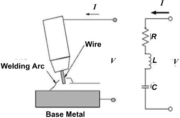
Flux cored arc welding and its equivalent circuit
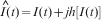
The input electrical impedance Zin(t) of the equivalent circuit is obtained by probing the welding voltage and current simultaneously at the input port of the welding system. Conventionally, the signal processing of Zin(t) is carried out by applying Fourier transform to the signals and later by calculating the result in frequency domain. However, the drawback is that the result does not reflect Zin(t) in real time. Therefore, the Hilbert transform is employed to calculate the time varying Zin(t).
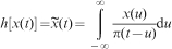
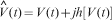
Hilbert transform of a real valued time domain signal, x(t), is denoted as h[x(t)], or
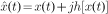
 , which yields the original signal in its analytic form,
 . Although the analytic signal is defined as a magnitude function of A(t) and an instantaneous phase function of θ(t), it is different from the Fourier transform of x(t) in its complex valued frequency domain signal X(ω). The main difference is that both magnitude and phase are functions of time, which means that they not only provide the information in frequency domain but also vary with time. This feature is especially important to obtain Zin(t) because it is capable to provide the time varying properties of the welding system.
Theoretically, the Hilbert transform of any raw signal can be defined as14
Measurement of Zin(t)
The detail of experimental set-up is shown in Fig. 3. The welding torch was attached to a two-axis Cartesian robot so that the leading angle, wire extension and welding speed can be controlled. This welding torch was also connected to a contact relay so that the welding process was initiated by automatic triggering. In order to hold the welding torch and prevent heat damage to the robot during the welding process, a custom made torch holder with heat isolator was designed and built.
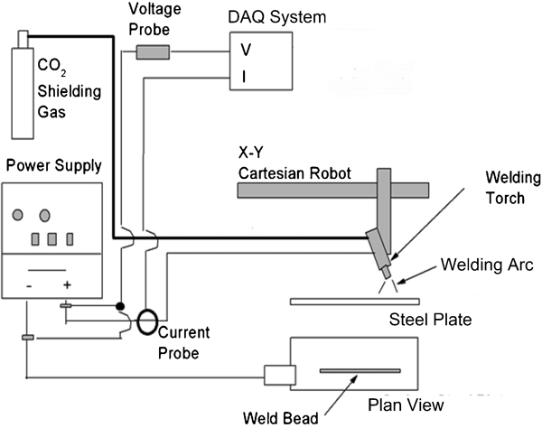
Schematic diagram of experimental set-up
Flux cored arc welding, Panasonic KRπ500, was used in this research as the welding process to carry out the bead on plate test15 for low carbon steel (AISI 1023) plates. The thickness of the steel is 15 mm. During the experiments, welding voltage and current were varied according to Table 1, while the other important welding parameters were fixed as follows: wire diameter = 1·2 mm; wire extension = 15 mm; welding speed = 7·5 mm s−1; leading angle = 15°; flowrate of CO2 shielding gas = 20 L min−1; welding time = 20 s.
Setting of welding voltage and current
For the acquisition of welding voltage and current signal, voltage probe (Tektronix, P520) and current probe (Hioki, 3285) were used to acquire the signals. The voltage probe was attached to the output terminals of the welding machine in order to measure the dc voltage. The current probe was hooked on the welding power cable as shown in Fig. 3 to measure the dc current. These input signals were sampled simultaneously and digitised by the DAQ system (National Instrument, SCXI-1305, 1000 and DAQCard-6062E) at 3 kHz. On the other hand, a built-in analogue filter with 100 Hz cutoff frequency was used for individual channel to prevent signal aliasing.
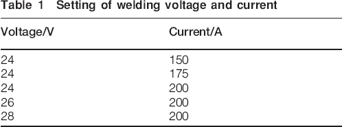
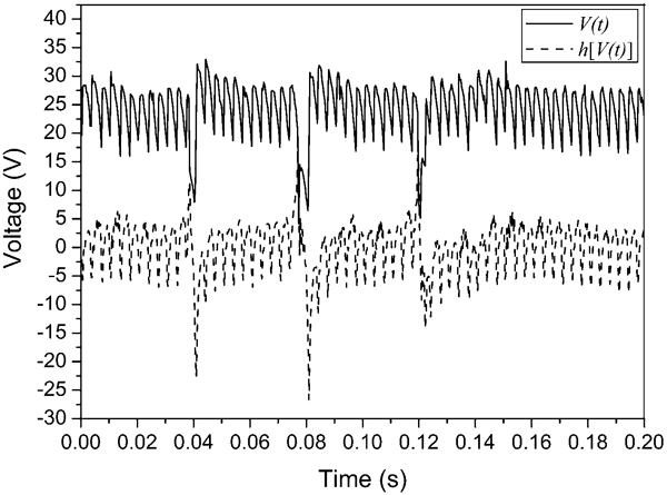
As shown in Figs. 4 and 5, the experimental result of real valued V(t) and I(t) based on 24 V and 150 A welding parameters setting are plotted for 0·2 s of welding time. In order to convert both real valued signals into analytic signals, the Hilbert transform was calculated. It shows that the Hilbert transform of V(t) and I(t) oscillates at the same frequencies of V(t) and I(t) except the frequency at 0 Hz. This result agrees with the modulation property of Hilbert transform, in which the Hilbert transform of any real valued x(t) is equal to zero at 0 Hz.14 After combining the V(t) and I(t) with h[V(t)] and h[I(t)] according to equations (5) and (6), Zin(t) was then calculated based on equation (7). All the calculations were performed using Matlab.
Transient welding voltage and h[V(t)]
Transient welding current and h[I(t)]
Zr(t) and Zx(t) of Zin(t) are then plotted in Fig. 6. It is observed that Zr(t) oscillates at positive value as the reflected resistance of the welding system. On the other hand, Zx(t) oscillates at zero value as a result of energy exchange between L(t) and C(t), which is commonly seen in an electrical R–L–C circuit. With these observations of experimental results, the presence of inductor and capacitor in the welding system is confirmed. Furthermore, Zr(t) has to reflect the resistance of the welding system accurately since the influence of inductance and capacitance is naturally isolated and presented in Zx(t).
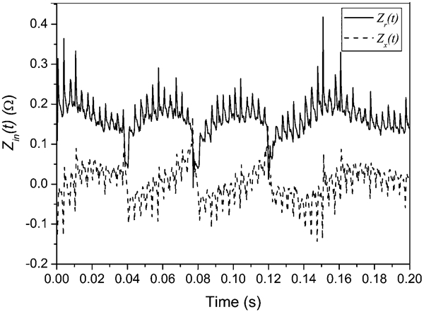
Typical time record result of Zin(t)
Discussion
In order to demonstrate the error of resistance caused by the influence of inductance, Zr(t) is compared with the conventional resistance, R(t), which is obtained using equation (2) based on the measured welding voltage and current. Figure 7 shows a typical comparison between Zr(t) and R(t) for 0·1 s of welding time. It can be seen that Zr(t) is always lower than R(t). Obviously, the difference between R(t) and Zr(t) is the measurement error caused by the influence of Zx(t) as presented in Fig 6. On the other hand, this error can be critical because it will lead to a significant error of arc power calculation, which will be discussed below.
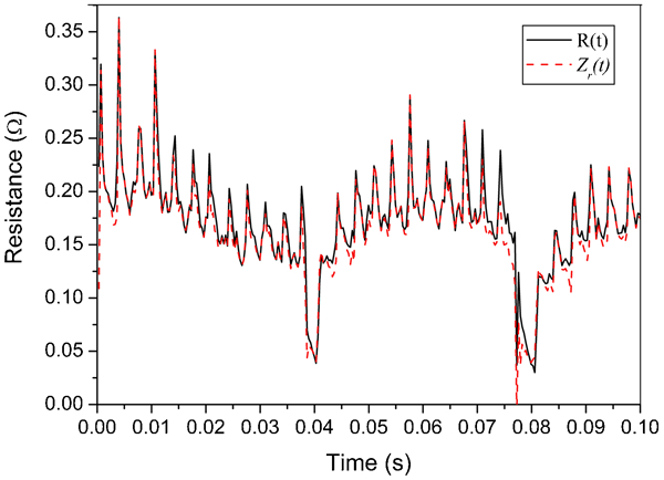
Comparison between Zr(t) and R(t) along welding time
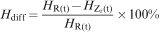
According to Table 1, five cases with variation of welding voltage and current were studied in order to evaluate the effect of inaccurate resistance measurement on arc power calculation. For each case, five experiments were carried out to confirm the repeatability of results. The results of measured R(t) and Zr(t) were averaged out and listed in Table 2. The arc power was then calculated according to equation (1) based on the averaged R(t) and Zr(t). Subsequently, the difference of arc power for each case was therefore computed according to equation (9).
Measurements of averaged R(t) and Zr(t)
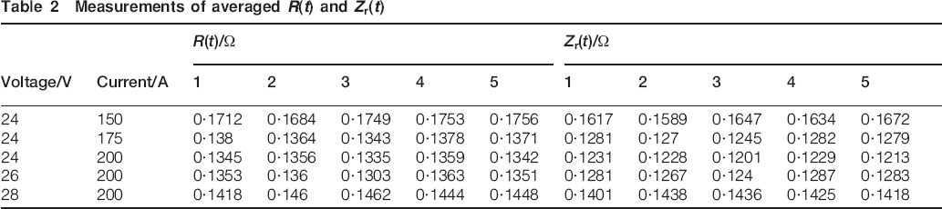
Figure 8 shows the comparison of arc power based on variation of welding current and voltage. It is observed that the arc power based on Zr(t) is always lower than the arc power obtained by R(t) because Zr(t) is lower than R(t) as shown in Table 2. This result further proves that some portion of the electrical energy is not converted into heat but conserved in Zx(t). In other words, Zr(t) allows us to calculate the actual arc power. On the other hand, the comparison results also reveal that low welding voltage always causes larger difference because more energy is conserved in Zx(t). Conversely, the energy being conserved in Zx(t) is lesser for high welding voltage because the capacitance appearing in Zx(t) is possible to compensate for high inductance
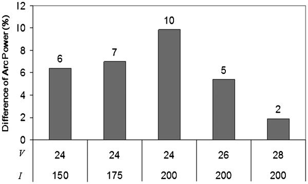
Comparison of arc power based on variation of welding current and voltage
Conclusions
A unique method was proposed in this paper to obtain the accurate resistance based on the input electrical impedance of a welding system. When the welding system is represented by an equivalent circuit, the input electrical impedance, which consists of resistor, inductor and capacitor connected in series, can be correlated with the dynamic welding mechanism of the welding system. Therefore, the two major components of impedance, namely, resistance and reactance, are important for obtaining the system parameters of the welding system.
The results presented in this paper confirm that the proposed method using the resistance of impedance for arc power calculation is more accurate as compared to the conventional approach. The error of arc power calculation incurred by the influence of inductance can range from 2 to 10% depending on the welding voltage and current setting. Since the proposed method can obtain the resistance of the welding system without the influence of inductance, it is a better approach as compared to the current method of obtaining the arc power.
Since R(t), L(t) and C(t) of Zin(t) can be correlated with the dynamic welding mechanism, they become effective monitoring signatures to evaluate the weld quality or characterise the welding process. In theory, real time weld quality monitoring and characterisation of welding mechanism can be achieved because the proposed monitoring signatures are time varying. By selecting the features of R(t), L(t) and C(t) carefully, they can be correlated with the physical result of weld quality inspection. Furthermore, the proposed monitoring signatures can be correlated with the physical change of welding mechanism so that online characterisation of the welding process can be achieved. More related work on real time weld quality monitoring and characterisation of welding process will be carried out, and the results will be published in near future.
Footnotes
Acknowledgements
The authors wish to thank Dr B. Osamu from Jurong Shipyard Singapore for his technical assistance and Sembcorp Marine Technology Pte Ltd Singapore and Maritime and Port Authority of Singapore for providing research fund, experimental workshops and equipments.