
Abstract
Weldability is one of the key requirements for automotive materials. This two-part paper aims at understanding the metallurgical phenomena during resistance spot welding of stainless steels, as interesting candidates for automotive body in white. Part I addresses the phase transformations in the fusion zone of three types of stainless steels including austenitic, ferritic and duplex types. The solidification and solid state phenomena including columnar to equiaxed transition, ferrite–austenite post-solidification transformation, martensitic transformation and carbide precipitation are discussed. Particular attention is given to the effect of high cooling rate of resistance spot welding process on the ferrite–austenite transformation. Key factors controlling the hardness of the fusion zone are highlighted.
Introduction
Materials selection is a key stage for the vehicle design. Increasing global demands for energy conservation, environmental protection and improved crashworthiness have prompted automotive manufactures to develop lightweight automobiles.1, 2 Vehicle weight reduction can be achieved by replacing heavy steel components with materials such as advanced high strength steel (AHSS), aluminium, magnesium or glass fibre reinforced polymer composites. 3
The possibility of using stainless steels in structural automotive was studied by a next generation vehicle (NGV) programme.4, 5 Next generation vehicle demonstrated that using stainless steels reduces weight and, at the same time, increases safety, sustainability and environmental resistance of the structural automotive systems. Stainless steel can be used in door pillars including A and B pillar reinforcement parts, bumper beams, rollover bars, crash boxes, suspension/wheel housings and subframes.4–6 Under impact, high strength austenitic and duplex stainless steels (DSSs) offer excellent energy absorption in relation to strain rate. Therefore, they are ideal for the revolutionary ‘space frame’ car body structure concept. Moreover, nowadays, using austenitic stainless steels (ASSs) and ferritic stainless steels (FSSs) in structural frameworks and body panelling of buses and coaches is widely accepted. 5
Resistance spot welding (RSW) is a critical joining process in vehicle production. Vehicle crashworthiness, which is defined as the capability of a car structure to provide adequate protection to its passengers against injuries in the event of a crash, largely depends on the integrity and the mechanical performance of the spot welds.7–9 Therefore, study of welding metallurgy of stainless steel sheets is a prerequisite for their use in automotive structural parts. Mechanical performance of resistance spot welds is significantly affected by:7, 10–15
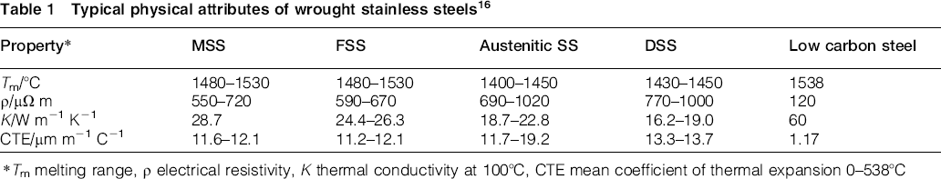
weld physical attributes, particularly the fusion zone (FZ) size: the weld nugget size is controlled by heat generation and heat dissipation, which in turn are governed by electrical resistivity and thermal conductivity of the metal sheets being welded respectively.
7
Table 1
16
shows a summary of physical properties of the ASS, FSS, martensitic stainless steel (MSS) and DSS compared with low carbon steel. The higher electrical resistivity and lower thermal conductivity coupled with the lower melting temperatures of stainless steels contribute to the lower currents and shorter welding times, which are necessary for the development of an acceptable weld nugget. The high coefficient of thermal expansion of stainless steels compared to the low carbon steels make them more susceptible to solidification cracking during welding metallurgical factors: mechanical properties and failure behaviour of the spot welds depend on the weld metallurgical characteristics including microstructural and hardness characteristics of the weldment. It is shown that the hardness characteristic, which in turn is governed by weld phase transformations, is the key controlling factor in interfacial to pullout failure mode transition of resistance spot welds.
7
Therefore, studying the phase transformations in FZ and heat affected zone is critical for understanding the failure mode behaviour and mechanical properties of the joints. Typical physical attributes of wrought stainless steels
16
Tm melting range, ρ electrical resistivity, K thermal conductivity at 100°C, CTE mean coefficient of thermal expansion 0–538°C
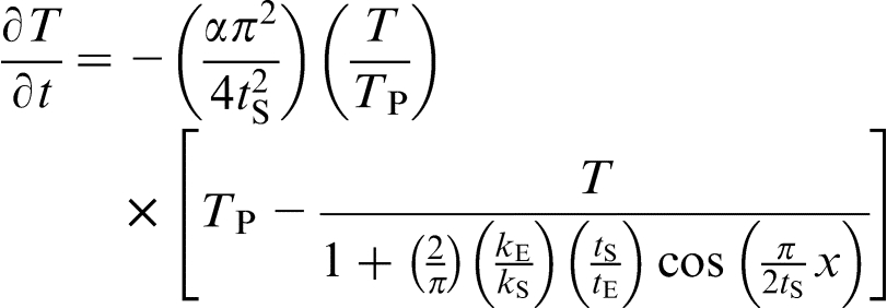
The phase transformations in FZ of stainless steel weldments including solidification transformations, ferrite–austenite transformation and carbide precipitation are controlled by the ratio of chromium equivalent to nickel equivalent (Creq/Nieq) and the cooling rate.17–20 The cooling rate of RSW is significantly higher than that of the conventional arc welding processes. Gould et al.
21
proposed a simple analytical model predicting cooling rates of resistance spot welds, as follows
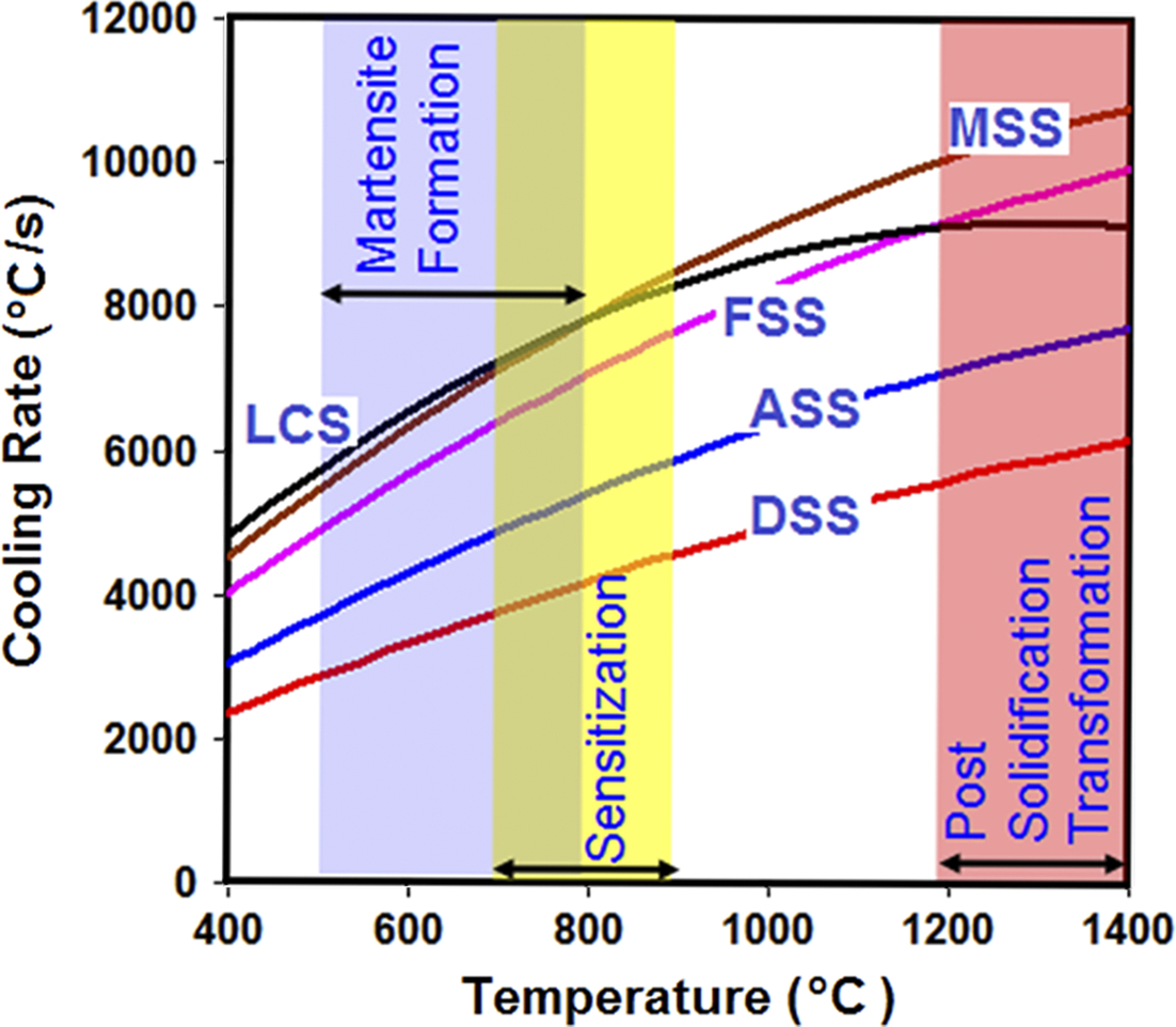
Calculated cooling rates during resistance spot welding of stainless steels and low carbon steel at sheet/sheet interface. Sheet thickness is 1.2 mm. Typical values for physical properties of steels are used for calculation. Peak temperature of weld nugget during welding is assumed to be 200°C higher than melting point. Electrode face thickness is 8 mm. Value of 320 W m− 1 K− 1 is considered for thermal conductivity of class II resistance welding manufacturing alliance copper based electrode
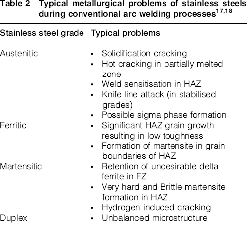
Welding and joining of stainless steels is an interesting issue in welding community. Welding metallurgy of stainless steels joints during arc welding processes is well researched. 17 Table 2 shows a summary of typical metallurgical problems during welding of stainless steels.17, 18 However, there are limited publications on resistance spot weldability of stainless steels.22–27 The current understanding of the process–structure–property relationships is limited for RSW of stainless steels. Therefore, improving the knowledge regarding the microstructural characteristics and failure behaviour of stainless steels is a priority for the successful implementation of new design in vehicle applications.
This two-part paper investigates the welding metallurgy of three types of stainless steels including asutenitic, ferritic and duplex grades during RSW. The aim of the present part is to investigate and analyse the solidification and solid state phenomena in FZ of stainless steel resistance spot welds. In the second paper, the phase transformations in heat affected zone and mechanical performance of the welds are discussed.
Experimental
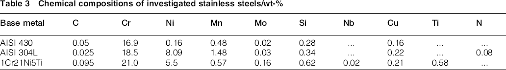
Three different types of stainless steels were used as the base metals, including AISI 304L ASS, AISI 430 FSS and 1Cr21Ni5Ti DSS. The chemical compositions of the sheets used in this study are given in Table 3. The sheet thickness for all steels is 1.2 mm.
Chemical compositions of investigated stainless steels/wt-%
Resistance spot welding was performed using a 120 kVA ac pedestal type RSW machine operating at 50 Hz controlled by a programmable logic controller. Welding was conducted using a 45° truncated cone resistance welding manufacturing alliance class 2 electrode with 8 mm face diameter. Squeeze time, welding time, electrode holding time after current off and electrode pressure were kept constant at 0.8, 0.24, 0.2 s and 4 bar respectively. Welding current was incrementally increased from 7.5 to 11 kA with a step size of 0.5 kA.
Samples for metallographic examination were prepared using standard metallography procedure. Optical microscopy was used to examine the microstructures of the joints. Marble etchant (10 g CuSO4, 50 mL HCl and 50 mL H2O) was used for macrostructural examination of the joints. Mixed acids reagent (10 mL HNO3–10 mL C2H4O2–15 mL HCl) was used for examination of FZ microstructure of ASS weld. Kalling's no. 1 reagent (33 mL H2O, 1.5 g CuCl2, 33 mL HCl and 33 mL C2H5OH) was used for examination of FZ microstructure of ferritic and DSS welds. Vickers microhardness test was performed using an indenter load of 100 g for a period of 20 s.
Results and discussion
Microstructural evolution in FZ of austenitic stainless steel spot welds
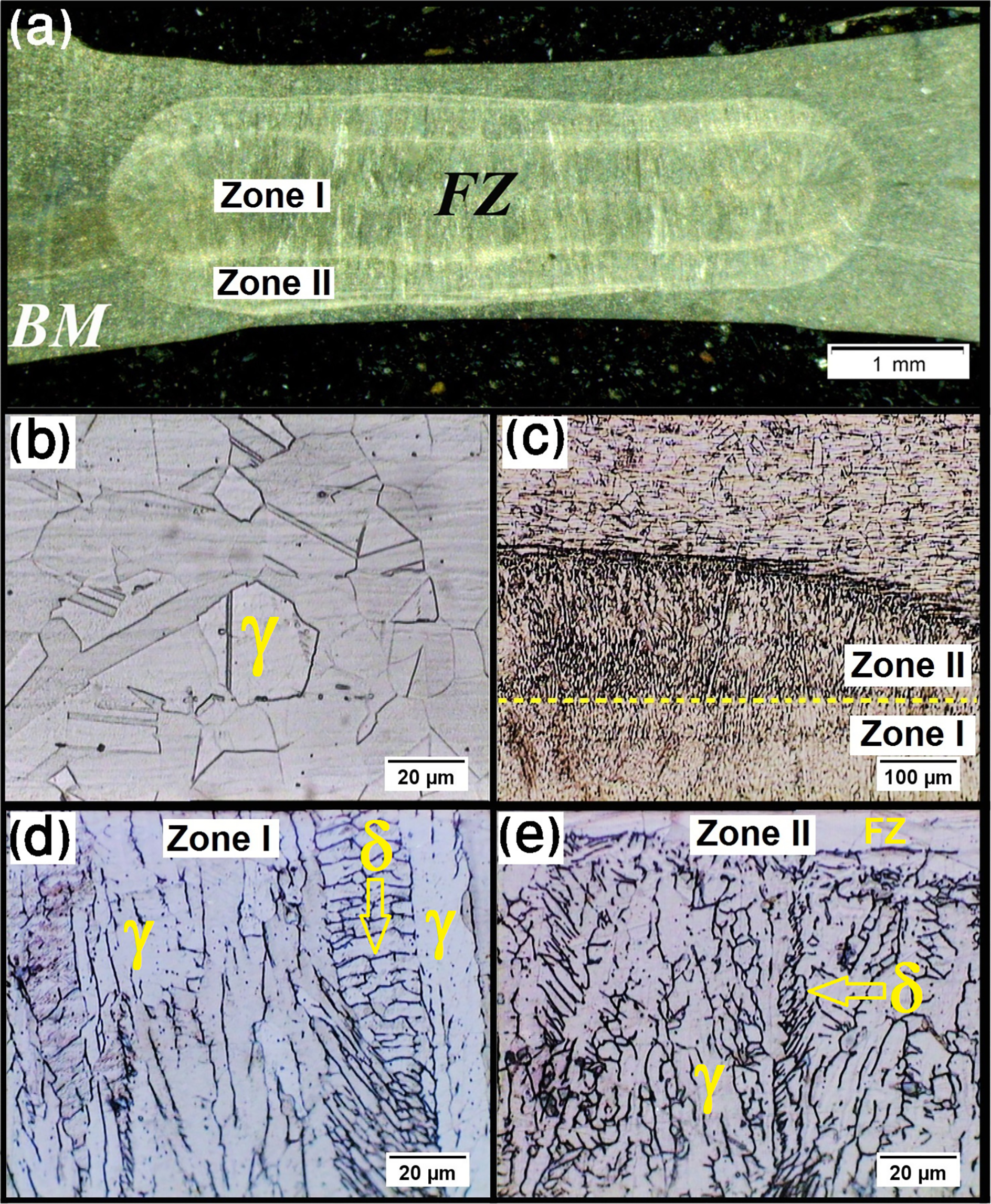
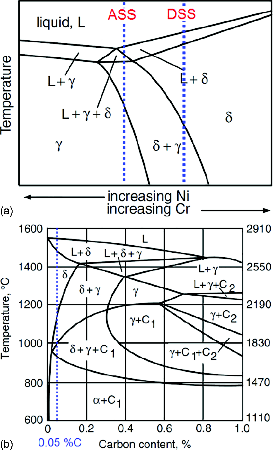
Figure 2a shows a typical macrostructure of ASS spot weld. In FZ, the full austenitic structure of the base metal (Fig. 2b) transforms to a dual phase microstructure consisting of austenite plus lathy delta ferrite (Fig. 2c). The morphology of ferrite suggests that solidification occurred at FA mode under rapid cooling condition. According to Fig. 3a, the solidification and post-solidification transformation path can be summarised as follows
17
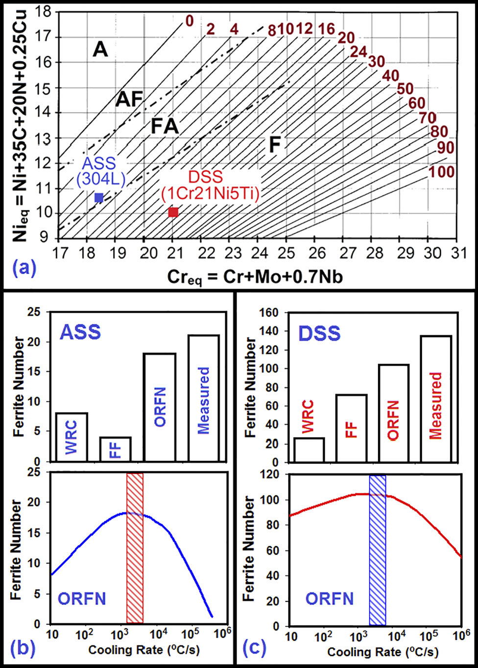
ferrite content of the weld nugget: it is interesting to note that AISI 304L welds exhibited two distinct regions in weld nugget, marked by zone I at the nugget centre and zone II at the nugget periphery (Fig. 2a). The dual core characteristic of the weld nugget is related to the difference in volume fraction of δ-ferrite phase at nugget edge and nugget centre (Figs. 2c and d). Microstructural examination showed that the volume fraction of δ-ferrite phase at nugget edge (∼24%) is higher than that at nugget centre (∼14%). The ferrite content of the FZ is determined during ferrite–austenite transformation. During this reaction, austenite consumes the ferrite via a diffusion controlled reaction. When FZ solidifies in FA mode, the ferrite content increases with increasing cooling rate because the diffusion controlled solid state transformation of ferrite–austenite (stage III) has less time to occur at high cooling rates, and therefore, the FZ has higher amount of residual ferrite. Therefore, the higher δ-ferrite at nugget edge compared to that at nugget centre can be related to the higher cooling rate at nugget edge than that of at the weld nugget edge due to the enhanced quenching effect of water cooled electrodes fusion zone microstructure prediction using conventional constitution diagrams: the solidification mode and ferrite content of the weld FZ of ASS can be predicted by the WRC-1992 diagram developed by Kotecki and Siewert
28
and function fit model proposed by Babu et al.
29
WRC-1992 (Fig. 4a) predicts an FN of 8. In function fit mode, using a thermodynamic approach, the difference in free energy between ferrite and austenite was calculated as a function of composition, and this was related to the FN. The function fit model (accessible online at Ref. 30) predicts an FN of 4 (Fig. 4b). Both model predictions are well below the measured FN. WRC-1992 diagram and function fit model were developed based on arc welding data. The underestimation of FN using WRC-1992 can be attributed to the high cooling rate of RSW compared with those of arc welding processes, which suppresses solid state austenite–ferrite transformation resulting in a higher non-equilibrium residual ferrite content in the FZ. Vitek et al.31, 32 developed a model, called ORFN (accessible online at Ref. 33), for predicting ferrite number in stainless steels welds as a function of cooling rate and composition. According to Fig. 1, the cooling rate of austenitic welds in the range of 1200–1400°C, where ferrite–austenite transformation occurs, is approximately 7800–8700 K s− 1. According to the ORFN model (Fig. 4b), considering the cooling rate effect, the predicted FN is 18, which is much close to measured FN. a typical macrostructure of AISI 304L austenitic stainless steel resistance spot weld, b base metal microstructure, c microstructure gradient in fusion zone, d microstructure of weld nugget centre (zone I) and e microstructure of weld nugget edge (zone II); volume fractions of δ-ferrite at weld nugget centre (zone I) and weld nugget edge (zone II) are different a schematic showing solidification and post-solidification transformation path in austenitic stainless steel and duplex stainless steel welds and b vertical section of Fe–Cr–C phase diagram at 17%Cr; blue dashed line shows transformations path in fusion zone of AISI 430 containing 0.05% carbon Prediction of fusion zone microstructure using WRC-1992, function fit (FF) model and ORFN model: a WRC-1992 diagram and b, c predicted versus measured ferrite number for AISI 304L austenitic and 1Cr21Ni5Ti duplex stainless steels respectively. Measured volume fraction of ferrite Vf was related to the ferrite number using FN = (Vf)[−0.025813(Fe)2 + 5.408679(Fe) − 102.3902], in which Fe is iron content of base metal in wt-%.
32
Experienced cooling rate by welds are specified
It is interesting to note that when ferrite is present in the FZ of ASS welds, sigma phase embitterment may occur by an exposure to temperatures between 500 and 800°C. 18 Owing to high cooling rate of the RSW process, the formation of sigma phase is not possible. According to Fig. 1, the cooling time between 800 to 500°C for AISI 304L RSW is estimated as 0.19 s. However, the decomposition of delta-ferrite to the sigma and austenite phase during ordinary aging process requires at least 0.5 h at 700°C. 34
Microstructural evolution in FZ of FSS weld
Figure 5a shows a typical macrostructure of the AISI 430 FSS spot weld. Large columnar ferrite grains are evident in the FZ (Figs. 5a and b) compared to the fine grains of the base metal (Fig. 5c). The microstructure of the FZ is composed of columnar ferrite grains featured by extensive fine precipitates plus some martensite at the grain boundaries (Fig. 5d). According to Fig. 3b, the solidification and post-solidification transformation path can be summarised as follows

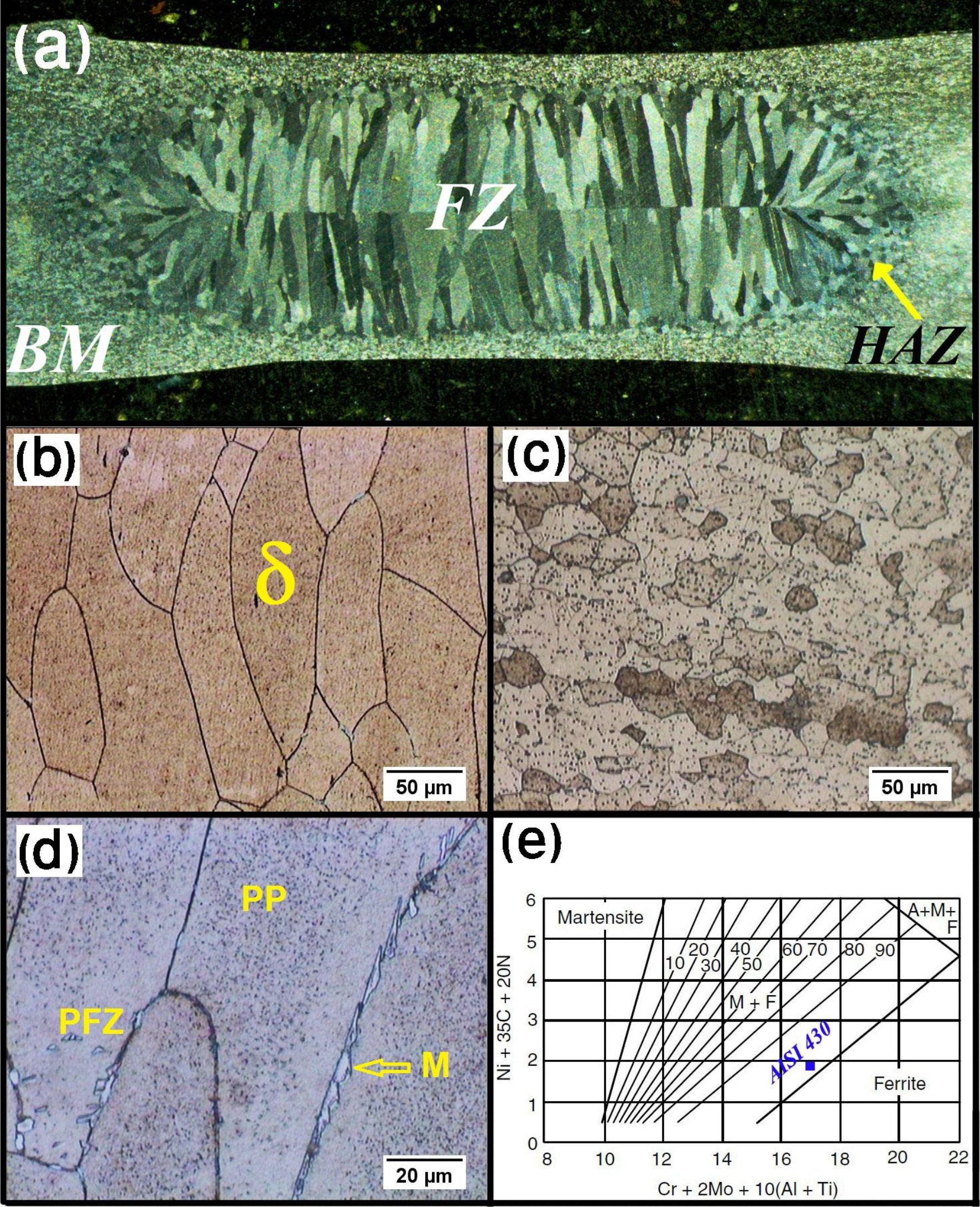
a a typical macrostructure of AISI 430 ferritic stainless steel resistance spot weld, b columnar grains in fusion zone, c base metal microstructure and d detailed microstructure of fusion zone showing ferrite grains decorated by extensive precipitates (PP) with some martensite (M) at grain boundaries. Precipitation free zone is also evident within ferrite grains adjacent to martensite layer. e prediction of fusion zone microstructure using Balmforth diagram
grain growth of ferrite: large columnar grains are evident in the FZ (Fig. 5a and b) martensite formation: the formed high temperature austenite transformed to martensite upon cooling. According to Fig. 5e, the Balmforth
35
diagram, which can be used to assess the microstructure of the FSS welds, predicts a ferritic microstructure with small amount of martensite for the investigated steel, which is in accordance with metallographic observations (Fig. 5d) carbide precipitation: the FZ exhibits a fine dispersion of precipitates within the ferrite grains (Fig. 5d). It is shown that in unstabilised alloys such as type 430, these precipitates are primarily chromium rich carbides.
17
These precipitates form due to the supersaturation of carbon in the ferrite phase at elevated temperature. The solubility of carbon in 17 wt-%Cr alloys drops dramatically upon cooling, decreasing from 0.15 wt-% at 1400°C to ∼0.03 wt-% at 1000°C.
17
The intragranular nature of precipitates suggests precipitation at high cooling rate, which is a characteristic of RSW process precipitate free zone: according to Fig. 5d, there is a precipitate free zone in the ferrite beside the martensite (i.e. the austenite at high temperature) in the FZ. Owing to high solubility of austenite for carbon, it can act as a sink for carbon at elevated temperature. Short range diffusion of carbon from ferrite into the austenite reduces the local concentration in the ferrite, and upon cooling through the precipitation range, there is little or no driving force for precipitation.
17
Microstructural evolution in FZ of DSS spot weld
Figure 6a shows a typical macrostructure of the DSS weld. During welding, the balanced ferrite–austenite microstructure of the base metal (Fig. 6b) transforms to an unbalanced microstructure consisting high volume fraction of ferrite with small amount of austenite along the ferrite grain boundaries plus extensive precipitates (Fig. 6c). According to Fig. 3a, the solidification and post-solidification transformation path can be summarised as follows
unbalanced microstructure in FZ: austenite–ferrite phase balance is key issue in fusion welding of DSSs.
17
However, as can be seen, the FZ exhibited high volume fraction of ferrite (∼90%). Owing to high Cr/Ni ratio of DSSs, they solidified in F mode (i.e. the FZ is fully ferritic at the end of solidification). The volume fraction of austenite in the FZ is determined during post-solidification solid state transformation of ferrite–austenite during cooling. Indeed, the rapid cooling rate of RSW process significantly hinders the nucleation and growth process of the austenite formation resulting in improper phase balance (i.e. low austenite content) fusion zone microstructure prediction using conventional constitution diagrams: WRC-1992 (Fig. 4a) predicted a ferrite number of 25, which is equivalent to 16 vol.-% of ferrite for investigated DSS. Therefore, the WRC-1992 highly underestimates the FN. The function fit model (Fig. 4c) predicts an FN of 72, which is still lower than the measured value. The inability of WRC-1992 diagram and function fit model to predict the FN can be attributed to two factors:
the presence of a significant amount of titanium in the FZ (i.e. 0.58%), which plays important role in phase balance. Ti as a strong carbide former and ferrite promoting element can remove carbon from the matrix by the formation of TiC and reduce the tendency to austenite formation.
17
The function fit model, which considers the interaction of C and carbide forming elements, provides improved FN prediction however, the function fit model does not account for the effect of cooling rate. The calculated cooling rates for DSS in the temperature range for solid state ferrite–austenite transformation, i.e. 1200–1400°C, is about 6000–6800°C s− 1. According to the ORFN model, which considers both the cooling arte and Ti effect, the predicted ferrite number is 104, which is closer to the measured FN precipitation: dramatic precipitation reaction is evident within ferrite grains of the FZ (Fig. 6d). Since the investigated DSS is nitrogen free, these precipitates cannot be chromium nitride, which are commonly expected in DSSs weldments.17, 36, 37 The SEM-EDS of these precipitates (Fig. 7a) suggests that they are Cr rich precipitates. Since the solubility of carbon in ferrite is far less than that of the austenite, the high ferrite content of the FZ, after δ → γ phase transformation, provides high content of supersaturated carbon in the ferrite phase. Therefore, high affinity of chromium for carbon leads to precipitation of Cr carbide precipitates columnar equiaxed transition (CET) grain structure in the FZ: Fig. 6e indicates two markedly distinct structural zones in the FZ, columnar region at nugget edge and equiaxed zone inside the nugget. The CET is usually assumed to occur when the advance of the columnar front is blocked by equiaxed grains that grow in the constitutionally undercooled liquid ahead of the columnar dendrites.
38
The grain structure is generally related to the solidification conditions such as local thermal gradient G and local solidification growth rate R. It is generally believed that there is a critical G/R ratio for CET grain structure. A low G/R value implies a large zone of constitutional undercooling ahead of columnar grain front, which is essential for the formation of equiaxed grain structure.39, 40 The following points should be considered for explaining the CET in the FZ of the DSS resistance spot weld:
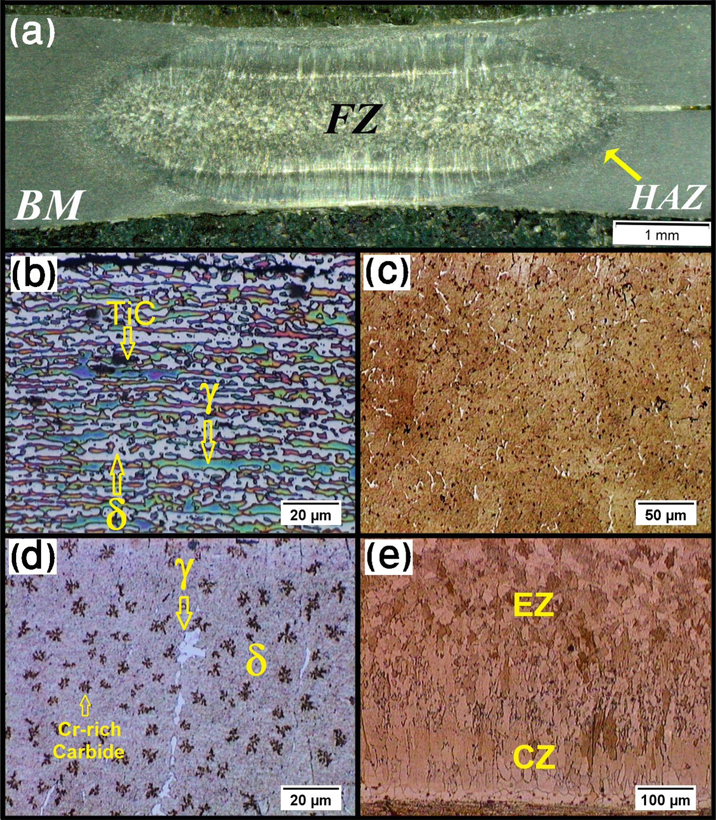
a typical macrostructure of 1Cr21Ni5Ti duplex stainless steel resistance spot weld; b base metal microstructure showing ferrite and austenite phase, dark particles are TiC; c, d detailed microstructure of fusion zone showing ferrite grains with some austenite grain boundaries along with Cr rich extensive precipitates; and e columnar to equiaxed transition in grain structure of fusion zone
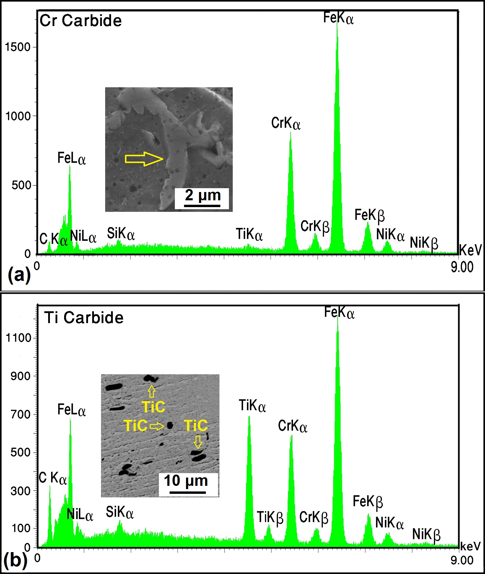
a Cr rich carbide in fusion zone; b Ti rich carbide in duplex stainless steel base metal
solidification conditions (G and R): during RSW, solidification generally initiates at the two opposing sides of the weld nugget at surfaces closest to the welding electrodes via epitaxial growth resulting in a coarse columnar grain structure with a preferred orientation. However, as the solidification proceeds, the ratio of G/R changes in a way that may promote the formation of the equiaxed grain structure at the weld centre:
as the solidification proceeds, the thermal gradient G drops due to increasing the distance of the solid–liquid interface from the electrodes as well as progressive release of the heat of fusion from weld pool as the solidification proceeds, the solidification rate R drops. This is again due to the reduced quenching effect of the water cooled electrodes resulting in lower heat conduction through electrodes and, hence, lower solidification rate Gould41, 42 in his work on the modelling of primary dendrite arm spacings in resistance spot welds determined solidification conditions (G and R) using a numerical thermal modelling. According to the results presented in Gould's work, during spot welding of 1.25 mm thick low carbon steel sheets, the values of G and R at the beginning of solidification are 2150°C mm− 1 and 16 mm s− 1 respectively. However, at the end of solidification, the values of G and R are reduced to 400°C mm− 1 and 8 mm s− 1 respectively. Therefore, the G/R ratio decreased from 135 to 50°C s mm− 2. The lowering of G/R ratio with progress of solidification can encourage CET in the FZ chemical composition of the weld pool: it is shown that increasing the alloying element content of the weld pool decreases the constitutional undercooling which in turn enhances the CET.
43
The carbon concentration in the steel may also be important in the CET. Carbon segregates strongly during solidification, which could increase the constitutional supercooling at the solid/liquid interface. In addition, high carbon levels can result in a higher density of carbides in the melt, which may act as nuclei for the equiaxed grains, as will be discussed later. Poole and Weinberg,
44
in their study on the CET in grain structure of cast stainless steels, found that when the carbon level is low (i.e. near 0.02 wt-%), there is no CET and the cast structure is entirely columnar. However, when the carbon content is more than 0.08 wt-%, a large portion of the casting exhibits equiaxed grain structure. In the present study, it is believed that the high carbon content of the investigated DSS (i.e. 0.095 wt-%) plays a major role in observation of CET in the weld nugget heterogeneous nucleation: the heterogeneous nucleation aided by constitutional supercooling promotes the formation of equiaxed grains in the weld metal. It is shown that nitrides, carbides, oxides and other materials which form particles in the melt, before solidification, could act as nuclei for heterogeneous nucleation. Bramfitt
45
demonstrated that titanium carbide is very effective in promoting heterogeneous nucleation for liquid iron. In the present work, the high carbon content coupled with high titanium content leads to formation of TiC particles in the base metal. The SEM-EDS (Fig. 7b) confirmed that the dark particles in the BM microstructure (Fig. 6b) are Ti rich carbides. The melting temperature of TiC was reported to be 3160°C, which is well above the maximum temperature of weld nugget during welding. Therefore, it can be concluded that TiC particles does not experience spontaneous melting but remain solid. Therefore, the pre-existing TiC particles in DSS sheets will act as inoculants to promote the nucleation of equiaxed grains in the FZ.
The change in the ratio of G/R during FZ solidification does not depend on the BM type. As it was seen above, the grain structure of austenitic and ferritic FZ are entirely columnar, while the DSS nugget exhibited a CET. Therefore, it can be concluded that the occurrence of CET cannot be entirely explained by the change in the solidification conditions (i.e. lowering of G/R ratio from weld nugget edge to weld nugget centre). Therefore, the main factor governing the CET in DSS is the pre-existing TiC particles in duplex steel base metal. The absence of pre-existing inoculant in ASS and FSS base metals explains why CET was not observed in their solidification structure.
Finally, it should be noted that the presence of equiaxed grain structure can improve the fracture toughness of the weld metal; however, high ferrite content of the FZ coupled with the presence of extensive Cr rich precipitates increases the brittleness of the weld and can be detrimental to corrosion resistance. Applying a proper solid state post-weld heat treatment can improve the ferrite/austenite balance and dissolve the carbide precipitates.
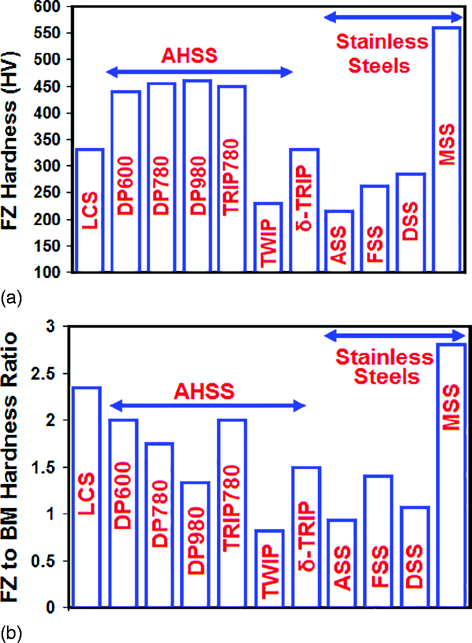
Fusion zone hardness
Hardness of the FZ is a key metallurgical factor in determining weld ductility and failure mode transition.
7
Figure 8a and b shows the hardness values of the FZ and the hardness ratio of FZ to BM for various types of stainless steels compared with low carbon steel
23
and AHSSs including dual phases,
46
transformation induced plasticity (TRIP),
47
twinning-induced plasticity
14
and δ-TRIP
48
steels. It is reported that high hardness of the FZ provides low fracture toughness path during coach peel and cross-tension loading conditions leading to interfacial failure mode. A critical FZ hardness of 400–450 HV has been defined by some researchers, which beyond that the interfacial failure is promoted.49, 50 As can be seen in Fig. 8a, the FZ hardness of the dual phase steels and TRIP steel exceeds 450 HV. However, the hardness of the austenitic, ferritic and duplex welds ranged between 215 and 285 HV, which is well below the detrimental hardness value:
the FZ hardness of ASS weld is determined by its ferrite content and grain size. While the base metal is full austenitic, the two-phase structure of the FZ can strengthen it. However, cast structure of the BM with large grain size leave undermines the effect of dual phase structure and leaves a slightly undermatch FZ compared to the BM hardness (Fig. 8b) the FZ hardness of the FSS weld is influenced by the ferrite gain size, volume fractions of grain boundaries martensite and carbide precipitation hardening. Despite, the large ferrite grains of FZ, the presence of martensite and extensive very fine precipitates produces high FZ to BM hardness ratio (Fig. 8b) the FZ hardness of DSS weld is dictated by the relative amount of γ/δ and their individual hardness as well as hardening via carbide precipitation. On the one hand, the unbalanced γ/δ microstructure and larger grains reduce the contribution of phase/grain boundary strengthening. On the other hand, extensive carbide precipitates and high ferrite content add contributions to the FZ hardness. Therefore, the FZ hardness is comparable to that of the base metal (Fig. 8b). a fusion zone hardness and b FZ/BM hardness ratio for various type of stainless steels including ASS, FSS and DSS (present work) and MSS
27
compared with low carbon steel
23
and advanced high strength steels (AHSSs) including dual phases
46
, TRIP780
47
, TWIP980
14
and δ-TRIP
48
steels; sheet thickness of all kind of steel sheets except TWIP steel is ∼1.2 mm
Conclusions
Understanding phase transformations during RSW of stainless steels is a key in understanding of mechanical and corrosion behaviour of the weldment. In this paper, the solidification and post-solidification solid state phenomena of austenitic, ferritic and DSSs during RSW are examined and analysed. The following conclusions can be drawn from this work.
The phase transformations of the FZ of austenitic and DSSs were significantly influenced by high cooling rate of RSW. The measured δ-ferrite content of the FZ of austenitic and DSS was higher than those predicted by the WRC-1992 constitutional diagram. The rapid cooling rate of RSW process suppresses the completion of post-solidification transformation of ferrite–austenite. The presence of Ti and high amount of carbon in the DSS plays key roles in microstructure development in the FZ of DSSs: as a strong carbide former and ferrite promoting element, Ti can remove carbon from the matrix by formation of TiC reducing the tendency for austenite formation pre-existing TiC particles in duplex steel base metal act as inoculants in the FZ promoting the CET. Fusion zone of austenitic, ferritic and duplex stainless welds exhibited significantly lower hardness values compared to ferritic–martensitic dual phase and TRIP AHSSs. Despite the FZ of ASS exhibited a duplex structure of austenite and ferrite, its cast structure with large grain size leaves a slightly soft FZ compared to the base metal. Despite the unbalanced FZ microstructure of DSSs, its hardness is comparable to that of the BM due to the presence of extensive carbide precipitates. The high FZ/base metal hardness ratio of the FSS is due to martensite formation and extensive carbide precipitation within the ferrite grains.