
Abstract
One technique for reducing residual stress in welds is high pressure rolling of the weld seam. In this study, a variety of experimental techniques, including microhardness measurements and cross-weld tensile tests with digital image correlation, have been used to characterise the effects of rolling on the mechanical properties and microstructure of the weld material in welded structural steel specimens. It is shown that rolling applied at high temperature, as welding is carried out, promotes the formation of acicular ferrite in the weld metal. This produces a weld material with a greater yield strength and hardness, but slightly reduced impact toughness compared to unrolled welds. Rolling of the weld metal once it has cooled instead causes work-hardening. These effects are discussed as they relate to the use of rolling for weld residual stress reduction.
Introduction
During all common welding processes, different regions of the welded material experience different thermal cycles. This creates a particularly unfavourable distribution of residual stress, with significant tensile residual stresses in and around the welded region. Such residual stresses can detrimentally affect resistance to elastic fracture, fatigue fracture and stress corrosion cracking.1 The development of welding residual stress is influenced by many factors (thermal, mechanical and material), and consequently, a broad range of methods have been used for residual stress reduction in this context.2 Localised high pressure rolling of the weld seam is one such technique and relies on causing plastic deformation of the weld region. Rolling compresses material in the direction normal to the weld's surface, causing it to expand in the plane of the weld, relaxing any tensile residual stresses in this plane. Recent work has shown that this method can completely change the distribution of stress in a weld, reducing it or even introducing compressive residual stresses into the weld region.3, 4 Rolling is only effective for residual stress reduction when it is applied after the welding process (here termed post-weld rolling) rather than during it (in situ rolling). This is because if rolling is applied at too high a temperature, subsequent yielding of the material as it cools overwhelms the effective strain which may be induced by rolling.3 While it has less of an effect on residual stress, in situ rolling was shown in one study by Kondakov to influence the development of weld microstructure in austenitic stainless steel and a titanium alloy;5 however, this effect has not been investigated in any modern literature.
The aims of the current two-part study are to investigate the effects of rolling on the microstructure and mechanical properties of welds (Part 1) and to observe variations in the residual stress distribution directly around the weld seam, which can be induced using different roller profiles (Part 2). In this first part of the investigation, several mechanical characterisation techniques have been applied to determine the changes in material properties and microstructure which result from the rolling of low carbon steel weld seams at different rolling temperatures and levels of roller force.
Experimental
Production of specimens
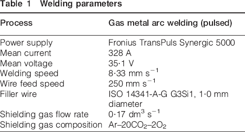
Linear bead-on-plate gas metal arc welds (600 mm) were prepared on 750×300×6 mm rectangular plates of S355JR structural steel. These welds were treated with high-pressure rolling either during welding (in situ) or post-weld, with an applied force of 12·5, 25, 50 or 100 kN. Plain as-welded specimens were also produced. The welding parameters, which were identical for all of the welds carried out, are given in Table 1.
Welding parameters
Both welding and rolling operations were carried out on a purpose-built rolling machine previously described elsewhere.3 During rolling, a constant force was applied using a roller actuated by a vertically-mounted hydraulic cylinder, and the roller/cylinder assembly was passed over the specimen at a constant velocity on a leadscrew-driven crossbeam. The specimens were held in place using a vacuum clamping system, which was applied to the entire underside of the specimen except for the region directly underneath the weld seam, where a copper backing bar (48 mm in width) was used. In all cases, only a single pass of rolling was applied, using the roller profile shown in Fig. 1. For post-weld rolling, the specimen was welded and left to cool for 600 s before rolling and then release of the clamps. For in situ rolling, the welding torch was mounted 100 mm in front of the roller axis and the two processes were carried out simultaneously. Again, 600 s was allowed for cooling before the vacuum clamps were released.
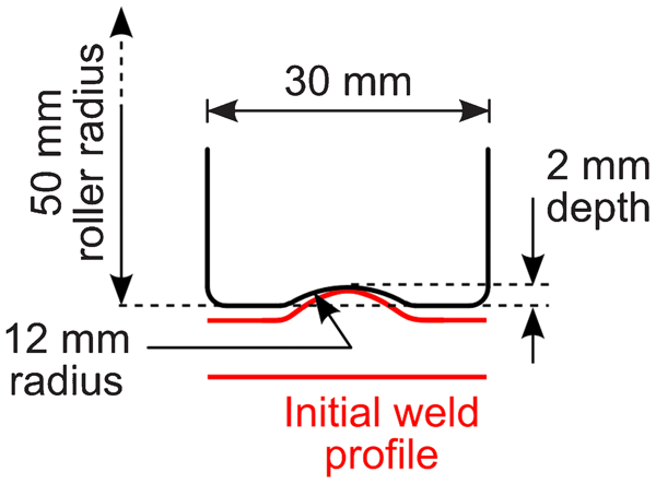
Schematic of roller profile, with comparison to profile of weld without rolling (taken from laser coordinate measurements)
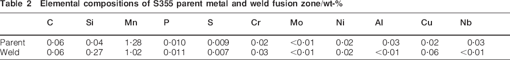
Several specimens were instrumented with K-type thermocouples on the upper surface, at various distances from the weld line, to a minimum of 20 mm from the centre of the weld. Data from these thermocouples were used to validate a sequentially-coupled thermomechanical finite element model of the process built using Abaqus/Standard v6·9-3 (Dassault Systems, France) and described in further detail elsewhere.6 This model was, in turn, used to determine the temperature field inside the weld metal. Samples of the parent plate remote from the weld and the weld metal inside the fusion zone were taken from a non-rolled specimen, and chemical analysis was performed via inductively coupled plasma optical emission spectrometry and combustion analysis. The resulting elemental compositions are given in Table 2.
Elemental compositions of S355 parent metal and weld fusion zone/wt-%
Cross-weld tensile testing
Tensile tests were carried out on specimens taken from the welded plates perpendicular to the weld line. Rectangular cross-section test pieces (see Fig. 2) were produced to conform to ISO 6892-1:2009 (Annex B).7 In all cases, the specimens were taken from the mid-thickness of the parent plate. Two-dimensional digital image correlation (DIC)8 was used to measure the strain variation across the frontal area of each specimen during the test and hence to investigate the localisation of strain due to the variation in mechanical properties across the weld (see Fig. 2), using the principle described by Reynolds and Duvall.9 A LIMESS DIC system (Correlated Solutions Inc., Columbia, SC, USA) was used for all measurements in this study.
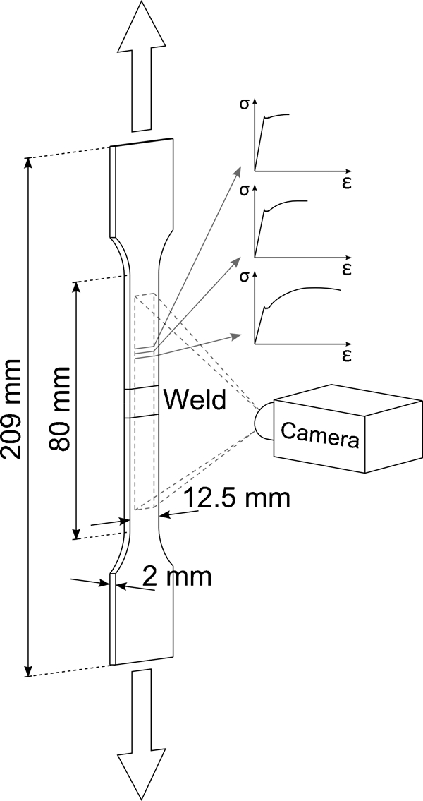
Cross-weld tensile test using DIC to observe local variations in strain and hence find the variation in stress–strain properties in the across-weld direction
Since the weld is relatively homogeneous along its length, it can be assumed that the tensile specimen's mechanical properties only vary in the loading direction, i.e. transverse to the weld. In addition, it is known that all cross-sections of the tensile specimen's gauge length must carry the same tensile force. Therefore, with a single tensile specimen, it is possible to produce a set of stress–strain curves, spatially resolved in the across-weld direction, in a manner similar to that described recently by Peel et al. 10 and Turski et al.11 In addition to the welded specimens, tensile samples consisting purely of the parent material were tested. During these tests, a conventional clip type strain gauge was used concurrently with the DIC method. This served to both check the accuracy of the DIC method and verify the stress–strain properties of the parent material. All of the tensile tests were carried out at an ambient temperature of 20°C and a constant elongation rate of 5 mm min−1.
Metallurgical examination, hardness and impact toughness
Cross-sectional metallurgical specimens taken from each weld were ground, polished and etched (2% nital, 12 s) before optical and SEM examination. The same samples were then measured for Vickers hardness: a Zwick/Roell Indentec microhardness measurement machine was used to make 372 individual measurements on each sample at spatial resolution of 0·5 mm using a mass of 500 g and an indentation time of 10 s.
Charpy impact tests were used to investigate the effect of rolling on the impact toughness of the weld metal. Transverse reduced-section Charpy V-notch specimens (5×10×55 mm) were taken from the mid-thickness of the welded plates, with the notch at the centre of the weld metal. Impact tests were then performed to ISO 148-1:201012 at a range of temperatures from −100 to 20°C and using a nominal pendulum energy of 400 J.
Results
Mechanical properties
Tensile tests
The tests of the parent material showed that the upper yield strength of the material was ∼475 MPa, the ultimate tensile strength was 520 MPa and the maximum elongation was 22·2%. It should be noted that these properties are substantially different to those given for the similar material used in Part 2 of this investigation,13 since material from different sources was used for the two studies.
Plots of the local strain occurring in different weld types (i.e. with no rolling, post-weld roiling and in situ rolling) and at different levels of tensile stress are shown in Fig. 3 (see also supplementary material 1 http://dx.doi.org/10.1179/1362171812Y.0000000079.S1 & 2 http://dx.doi.org/10.1179/1362171812Y.0000000079.S2). In all cases, the tensile strain in the weld metal and the surrounding heat affected zone (HAZ) is lower than in the surrounding parent metal at all levels of applied load. Outside the HAZ, at approximately 15–25 mm either side of the weld centreline, there are regions that initially show increased deformation compared with both the weld metal and the parent metal far remote from the weld. An example of this is marked by arrows in Fig. 3c. All of the cross-weld specimens tested ultimately failed in the parent metal remote from the weld and HAZ.
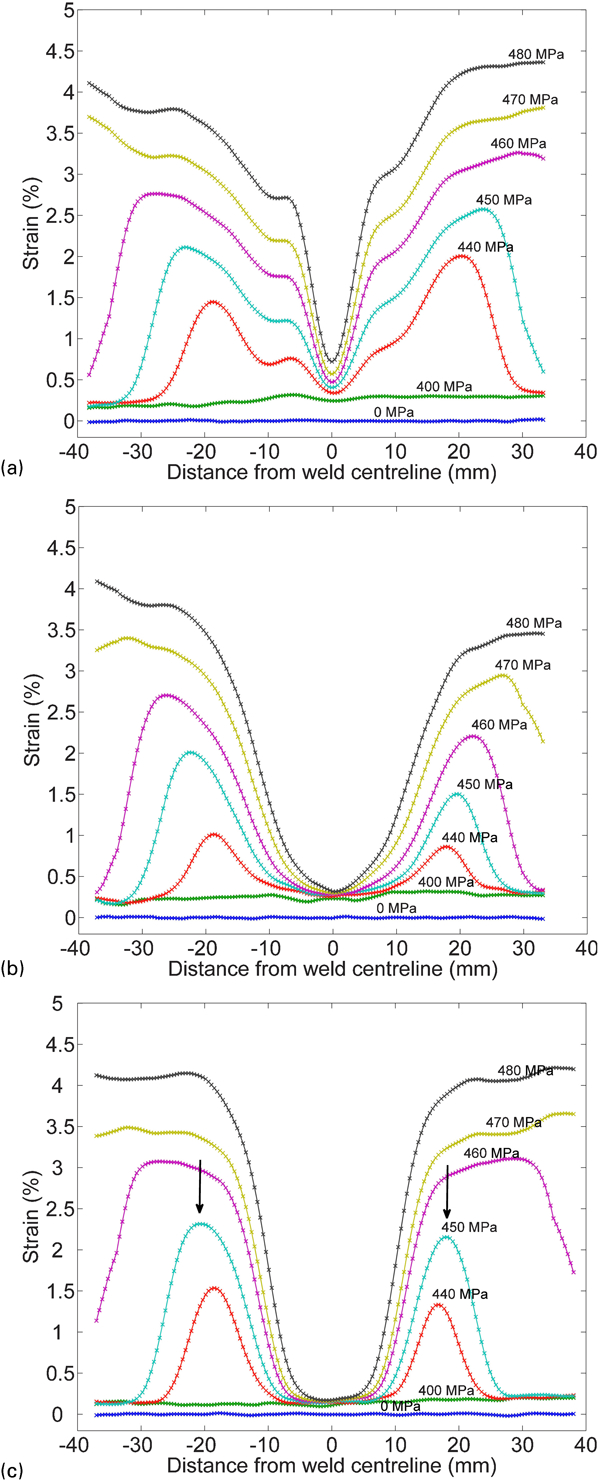
Tensile engineering strain as function of position and applied stress during uniaxial tensile tests
It is clear from Fig. 3 that both post-weld and in situ rolling have dramatic effects on the stress–strain properties of the weld. The result of this is perhaps best seen in the plots of offset yield stress shown in Fig. 4. Rolling the weld seam either post-weld or in situ raises the proof stress of the weld metal and surrounding region. During either process, higher levels of roller force result in a greater degree of hardening. For both of the specimens rolled at 100 kN, the parent metal failed before part of the material in and around the weld exceeded its proof strain (0·2% offset). In all specimens, well-defined yield plateaus were observed in the parent material, but not in the weld metal, regardless of rolling treatment.
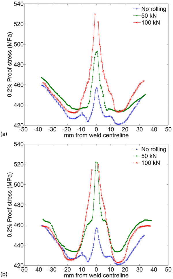
Variation in 0·2% offset yield strength across weld seams rolled at different levels of roller load
Hardness
Maps of Vickers hardness across transverse sections of the weld zone are shown in Fig. 5. In all cases, a clear change in hardness corresponding to the discontinuity in composition and microstructure across the fusion boundary is visible. In the sample that was not rolled (Fig. 5b), the HAZs are also visible to either side of the fusion zone, being slightly lower in hardness than either the fusion zone or the surrounding parent material. Post-weld rolling (Fig. 5c–f) results in an increase in hardness with increasing rolling load, especially in the fusion zone. The same is true for in situ rolling (Fig. 5g–j), although in this case the hardness increase is even more pronounced. The trend in weld and HAZ hardness therefore follows the trend in proof stress (Fig. 4), which is unsurprising since Vickers hardness and proof stress are related roughly linearly for most steels.14
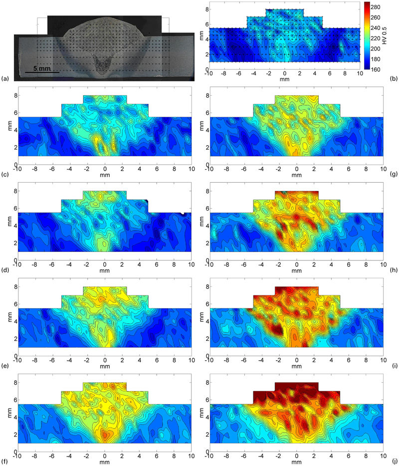
Cross-sectional maps of Vickers hardness (HV0·5/10) in welded specimens
Impact toughness
Ambient-temperature measurements of the weld metal's impact toughness are shown in Fig. 6a. The impact toughness of specimens rolled post-weld is almost invariant with rolling load, decreasing only very slightly at higher loads. The toughness of weld metal rolled in situ shows a greater reduction with increasing rolling load, although even at the maximum level of roller force (100 kN), the impact energy absorbed by the weld metal is only slightly less than that of the parent metal (41·3 J compared with 44·7 J).
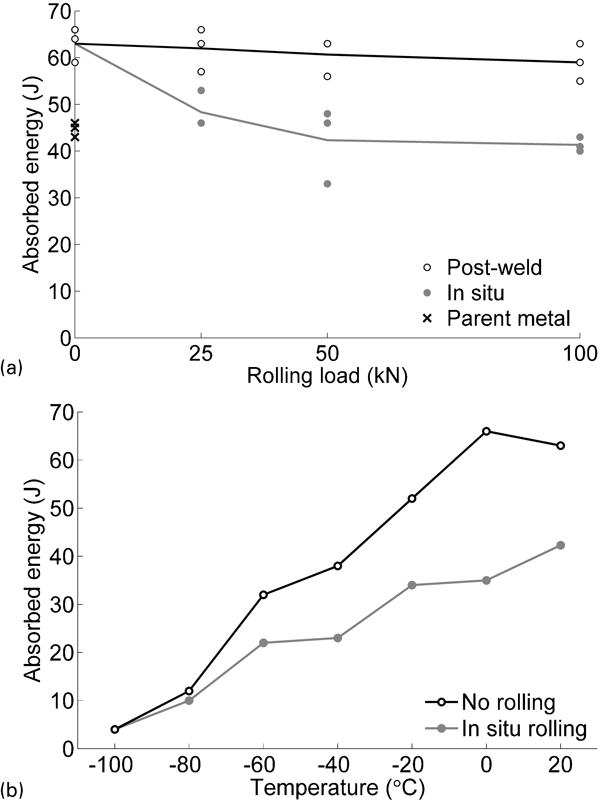
Absorbed impact energy for reduced-section Charpy V-notch specimens (5×10×55 mm) taken from rolled welds
The impact toughness at reduced temperature is shown in Fig. 6b. Both types of weld metal (i.e. without rolling and with in situ rolling at 50 kN) display an almost linear reduction in impact toughness on cooling from 20 to −100°C, with no well defined ductile-brittle transition temperature. The weld with in situ rolling is less tough than the conventional weld over the whole temperature range.
Microstructure
The optical micrographs in Fig. 7 compare the effects of post-weld and in situ rolling on the weld microstructure. Without rolling, the weld metal consists chiefly of a mixture of polygonal and Widmanstätten ferrite, with some acicular ferrite formations, which is typical for a low carbon steel weld of this type. The structure is similar after post-weld rolling (Fig. 7c and d); however, in situ rolling results in the very different microstructure shown in Fig. 7e and f. Fine paths of allotriomorphic and polygonal ferrite decorate the boundaries of the prior austenite grains, but otherwise, the microstructure consists almost entirely of fine-grained acicular ferrite. The SEM image in Fig. 8 shows this structure in greater detail: the grains have a length of 5–15 μm and a width of ∼2 μm.
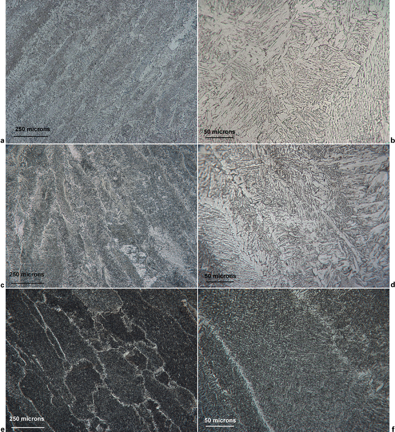
Optical micrographs of fusion zone of welded steel specimens
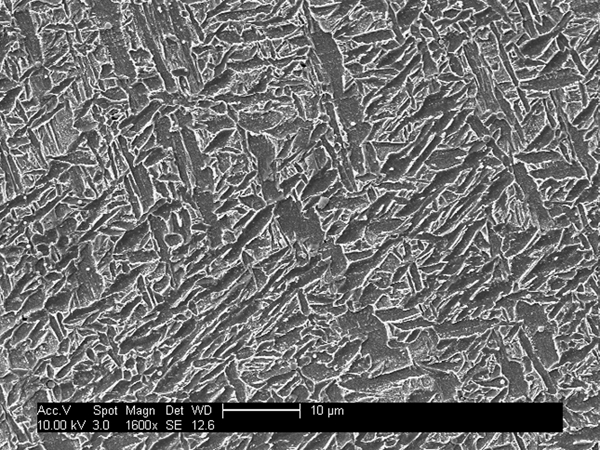
Acicular ferrite in weld metal of S355 steel weld rolled in situ at 50 kN (SEM image)
Discussion
Weld mechanical properties
The hardness of the unrolled welds (Fig. 5b) was both relatively low and quite homogeneous across the parent metal, HAZ and fusion zone. This suggests the absence of hard martensite, and indeed, no martensite is visible in the weld metal in Fig. 7. In all of the specimens, rolled and unrolled, increased plastic deformation was observed in regions 15–25 mm either side of the weld during the cross-weld tensile tests (see Fig. 3). Recrystallisation in the coarse grained HAZ is known to result in a decrease in yield strength in many cases, mainly due to a reduction in grain boundary hardening as larger grains are formed.15 However, here, the regions of increased deformation lie outside of the HAZ, the maximum extent of which was approximately ±7·5 mm. It is therefore likely that the softening of these regions is due to the recovery during welding of dislocations formed during the initial manufacture of the parent plates. This loss of work-hardening leads to increased plastic deformation in the recovered zones directly after yielding as the tensile specimen is loaded; however, as larger strains are induced, the material again work-hardens and becomes indistinguishable from the surrounding unaffected parent metal.
Influence of rolling on mechanical properties and microstructure
From the hardness maps shown in Fig. 5 and the cross-weld tensile test results in Figs. 3 and 4, it is clear that both post-weld and in situ rolling hardens the weld metal and causes an associated rise in the proof strength. For post-weld rolling, this is unsurprising, since work-hardening is an inevitable consequence of the plastic deformation induced during rolling. The lack of any significant difference in microstructure between the as-welded and post-weld rolled specimens (Fig. 7) confirms that work-hardening is the primary hardening mechanism. The hardness maps in Fig. 5b–f show that during post-weld rolling, substantially more work-hardening occurs in the fusion zone than in the surrounding HAZ, which is likely due to the slightly different composition of the weld metal (see Table 2). Work-hardening is seen to occur throughout the weld region, suggesting that rolling causes plastic deformation through the whole thickness of each specimen. For the welds rolled in situ, the temperature during rolling is too high for substantial work-hardening to occur; instead of work-hardening, in situ rolling causes microstructural change, resulting in the acicular ferrite microstructure shown in Fig. 8, which is the cause of the increased hardness.
During the γ→α transformation in a ferritic steel weld fusion zone, competitive growth occurs between ferrite growing from the austenite grain boundaries (in polygonal and Widmanstätten morphologies) and intragranularly nucleated acicular ferrite. 16 16,17 Many factors, including the cooling rate, prior austenite grain size and number density of intragranular inclusions, influence the kinetics of this transformation.18, 19 Additionally, stress applied during the transformation is also known to affect it when the chemical driving force is small.20 Figure 9 shows the effect of in situ rolling on the thermal cycle undergone by the weld metal: an increase in thermal conduction into the roller and backing bar results in a moderate increase in cooling rate, reducing the time between 800 and 500°C (t 8–5) from 11·2 to 6·6 s. The internal heat generation from rolling due to material viscoplasticity is negligible. Such a cooling rate increase favours the formation of acicular and Widmanstätten ferrite over polygonal ferrite and reduces the time available for austenite grain growth. However, available continuous cooling data for this type of material indicate that this increase in cooling rate would be insufficient to cause such a pronounced change in microstructure as seen here.21
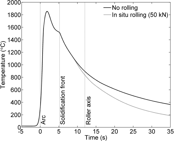
Thermal cycle at weld centreline halfway through thickness of specimen (modelled)
The weld undergoes rolling as it cools from approximately 900–700°C (see Fig. 9). Under equilibrium conditions, this range would lie largely within the material's intercritical region, i.e. between its Ac 3 and Ac 1 temperatures. However, since the weld cools continuously, it will still be almost fully austenitised as rolling takes place. Severe plastic deformation of the austenite grains is known to slow the growth of acicular ferrite by forming stable dislocation networks.18 In addition, such deformation can reduce the austenite grain size via dynamic recrystallisation, increasing the availability of intergranular nucleation sites.22 However, for the welds investigated here, the amount of plastic deformation induced by rolling is relatively small: a maximum of 13·4% principal plastic strain was observed in the simulations, and no reduction in austenite grain size was observed. Therefore, it is believed that the influence of this deformation in promoting intragranular acicular ferrite nucleation outweighs any detrimental effect on its growth; such an increase in intragranular nucleation would explain the very fine nature of the resulting acicular structure.
In general, acicular ferrite is a desirable component of a weld microstructure because its small and chaotically oriented grain structure results in good toughness without any decrease in strength.17 However, in this study, the acicular ferrite weld metal of the specimens rolled in situ was observed to be less tough than the polygonal/Widmanstätten microstructure of as welded specimens throughout the temperature range tested (see Fig. 6b). A possible explanation for this could be dynamic strain aging of the weld metal as it is rolled;23 however, no yield point elongation effect was observed in the weld metal during tensile testing, regardless of rolling treatment. Despite being less tough than conventional weld metal, the acicular ferrite of the in situ rolled weld still maintains excellent impact toughness, almost equalling that of the parent material.
Applications of weld rolling
Post-weld rolling is known to have a far greater effect on the residual stress distribution in a weld than rolling in situ (i.e. as welding is carried out) because, during in situ rolling, residual stresses can re-form after the roller has passed.3 However, it has been shown here that, in a steel weld, in situ rolling has an effect on the weld microstructure, which would be impossible to produce once the weld has cooled. Therefore, the most desirable rolling temperature depends on the motivation for the process: residual stress control or microstructure modification. Clearly, the effects of weld rolling would vary greatly for different alloy systems. It would therefore be advisable to consider the material's work-hardening characteristics (and any consequences of work-hardening), its ductility at the desired rolling temperature and the effects of deformation on any microstructural properties, if weld rolling is to be applied.
Conclusions
High pressure rolling of structural steel fusion welds results in an increase in yield strength and hardness in the weld metal and HAZ. This occurs regardless of whether rolling is carried out as the weld is made or after it has cooled.
For post-weld rolling, the observed increase in weld metal hardness is due to work-hardening. However, rolling the hot material directly behind the welding tool changes the microstructure of the fusion zone, causing the widespread formation of fine acicular ferrite, which also hardens the weld region.
The fine acicular ferrite microstructure that occurs in the fusion zone as a result of rolling during welding has a lower impact toughness than a weld without rolling. Nevertheless, its toughness is still excellent.
Hardness increases brought about by post-weld rolling were seen to extend throughout the 6 mm thickness of the weld, suggesting that the process can induce plastic deformation in structural steel to at least this depth.
Footnotes
Acknowledgements
Funding for this work was provided by Tata Steel Europe and the EPSRC under grant no. EP/G014132/1.