
Abstract
When fusion welding is conducted on the dissimilar materials between a reduced activation ferritic/martensitic steel F82H steel and an austenite stainless steel SUS 316 steel, δ ferrite is generally formed and inevitably deteriorates the weld properties. In this study, dissimilar welding of F82H to SUS 316 steel was successfully achieved by friction stir lap welding technique. It revealed that the shape and microstructure of the joint interface can be controlled by controlling the welding temperature, in another word, by changing the applied load. By controlling the welding temperature at ∼710°C, a sound dissimilar joint can be obtained with a smooth joint interface and no mixed microstructure, despite the relative overlapping position of the steel plates. All the dissimilar joints showed high shear tensile strength and fracture in the base metal of F82H steel plate, which has lower strength than the SUS 316 steel plate at room temperature.
Introduction
The primary advantage of dissimilar welding is that doing so allows the exploitation of the combined properties of different materials. However, successful welding of dissimilar materials is generally difficult by fusion welding methods due to their different properties such as the melting points, thermal expansion coefficients, thermal conductivities, etc. Although such welding is possible, the strength of the resulting joints will often be impaired by the formation of brittle intermetallic compounds or a mixed structure.1, 2
The friction stir welding (FSW) was invented by the Welding Institute of the UK in 1991 with the original purposes of joining of low melting materials such as Al, Mg and Cu alloys.3– 5 Since the FSW process is carried out at very low temperature below melting point, the chemical reaction between the different materials can be significantly reduced. Recently, there have appeared many publications on FSW of dissimilar materials, which were mainly focused on the welding of Al alloys to low melting point materials and Al alloys to high melting point materials for achieving combined properties of the joints.6– 10 Up to now, the study on the dissimilar FSW of high melting point steels is still very limited.
As a kind of reduced activation ferritic/martensitic steel, the F82H steel is the most promising candidate as a structural material for fusion power plant reactors. SUS 316 steel is used in the piping area of the International Thermonuclear Experimental Reactor test blanket modules.11 The welding of these two materials is designed to be used as the back wall in the reactors. However, when the fusion welding methods were performed for the dissimilar welding of F82H with SUS 316, the strength of the F82H steel side near the nugget area significantly decreased due to the generation of δ ferrite.12
In our previous study, the welding temperature during the FSW of high carbon steel could be controlled below AC1 by reducing the heat generation.13–
18 Frigaard et al.
19 reported that the total heat generation during FSW can be described as

In this study, FSW technique was applied to the dissimilar lap welding of F82H with SUS 316 stainless steel. As one of the process parameter, the factor P can be used to easily control the heat generation during the welding process. According to the previous study, a tungsten carbide (WC) based tool is one of the best selections for controlling the welding temperature during the FSW of steels due to its excellent toughness and good thermal conductivity.20 In this study, it revealed that using a WC based rotating tool, the lap FSW of F82H steel to austensite SUS 316 was successfully obtained at a peak welding temperature of ∼710°C at which the yield strength of these two materials are very similar and suitable for FSP process. In addition, the formation of intermetallic compounds and a mixed microstructure was prohibited.
Experimental
A kind of reduced activation ferritic/martensitic steel F82H and SUS 316 stainless steel plates was used as the base materials, which have dimensions of 250 (l)×50 (w)×1·5 (t) mm3. The F82H steel was fabricated by a hot isostatic pressing method.21 Their chemical compositions of the two plates are listed in Table 1. Figure 1 shows the variation of the yield strength of the SUS 316 and F82H sheet over temperature. The ambient yield strength of the F82H steel and SUS 316 is 530 and 205 MPa respectively and then decrease gradually with the increase in temperature. The 0·2% proof stress of the F82H steel and SUS 304 decreased with increasing temperature and then these values reversed over 710°C when the 0·2% proof stress of the SUS 316 becomes greater than that of the F82H. That means when the welding temperature is controlled at 710°C, the two different steels will have the same yield strength during the welding process, which is in a favour of the exploitation of the FSW technique.
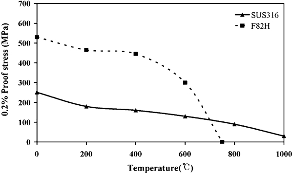
Proof stress (0·2%) of F82H steel and SUS 316 sheet over temperature range
Chemical compositions of F82H and SUS 316
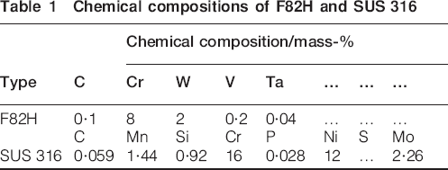
The welding temperature was measured by inserting K type thermocouples under the bottom of the upper plate along the joint interface. Therefore, the measured temperature corresponds to the value at the interface of the stir zone, and the cooling rate was determined from the peak temperature to 500°C. A detailed schematic illustration of the dissimilar lap FSW, the relative position of the SUS 316 and F82H steel sheets in the vertical direction and the position of the measured temperatures is shown in Fig. 2. The WC–Co rotating tool, which had a 15 mm diameter concaved shoulder, 6 mm diameter unthreaded probe and 1·9 mm probe length, was used during the welding process. The length of the probe was longer than that of the upper steel sheet. When the friction stir lap welding of SUS 316 on the F82H was performed, the rotation speed of 100 rev min−1 and welding speed of 100 mm min−1 were constant and the load changed from 25 to 30 kN to control the welding temperature. In this case, the welds were indicated as SUS 316/F82H lap weld. When the friction stir lap welding of the F82H on SUS 316 was performed, the rotation speeds were changed from 100 to 400 rev min−1, while the constant welding speed and load were 100 mm min−1 and 10 kN respectively. In this case, the load significantly decreased because F82H becomes easily softened at high temperature. Similarly, the welds were indicated as F82H/SUS 316 lap weld. During all the welding process, the tool was tilted 3° from the plate normal welding direction.
a SUS 316 on F82H; b F82H on SUS 316
The cross-sectional microstructure perpendicular to the welding direction of each FSW joint was observed by optical microscopy. The samples were first chemically etched with Keller's solution (1 vol.-% hydrofluoric acid, 1·5 vol.-% hydrochloric acid and 2·5 vol.-% nitric acid in solution) and then followed by electrochemical etching (in a solution of 10% oxalic acid and 90% water with a power supply set to 15 V for 60 s) to reveal the microstructure of both the base metal and the joint interface.
Electron backscattered diffraction (EBSD) analysis of the microstructure in the cross-section of the joint perpendicular to the welding direction was also carried out in a field emission type scanning electron microscope (JSM-7001FA) operated at 15 kV. The specimen for EBSD observation was electrolytically polished in solution of 20 mL HClO4+180 mL CH3COOH at −10°C for 30 s. The average grain size was determined from the EBSD phase maps by the mean linear intercept method. Energy dispersive X-ray spectroscopy was performed to determine the level of diffusion of the elements in the dissimilar lap welded joints and interface. Thin foils perpendicular to the welding direction of the samples were prepared for TEM observations by a focus ion beam system (JEOL JIB-4500).
The Vickers hardness distribution profile was measured along the thickness of the cross-section of the joint perpendicular to the welding direction with an applied load of 0·98 N and a dwell time of 15 s. For each welding condition, at least three specimens were wire cut perpendicular to the welding direction from the same joint for shear tensile tests. All the shear tensile tests were performed at a cross-head speed of 1 mm min−1.
Results and discussion
Temperature history
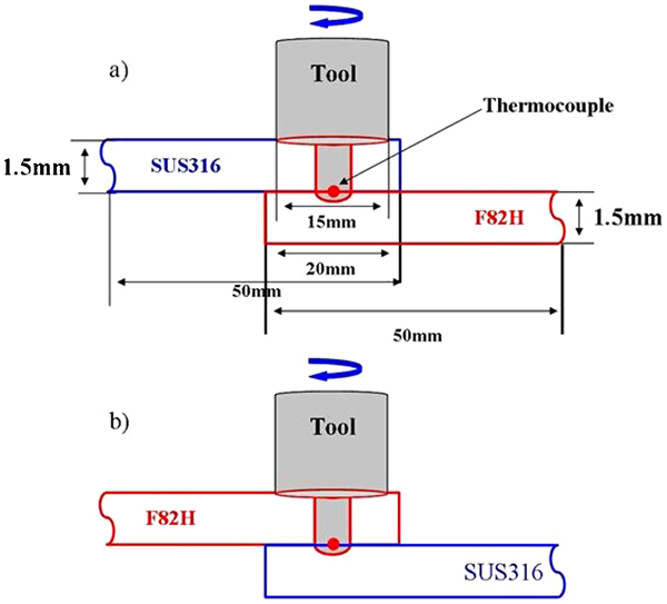
Figure 3 shows the typical temperature cycles for each welding condition during the dissimilar friction stir lap welding between SUS 316 and F82H. When the lap FSW of SUS 316/F82H was performed, the peak welding temperature decreased with the decrease in the applied load as shown in Fig. 3a. In particular, the measured peak temperature was 710°C when the welding was performed at a rotation speed of 100 rev min−1, a welding speed of 100 mm min−1 and an applied load of 27 kN. At this temperature, the yield strength of F82H and SUS 316 are approximately the same.
a SUS 316 on the F82H; b F82H on SUS 316
When the friction stir lap welding of F82H/SUS 316 was performed, the welding temperature decreased with the decreasing rotation speed as shown in Fig. 3b. In addition, when the applied load during the welding process increased from 10 to 18 kN, the measured peak temperature was 714°C. Similarly, the yield strengths of both F82H and SUS 316 were approximately the same. Although the welding conditions were different for the SUS 316 on F82H and the F82H on SUS 316, both conditions could approach almost the same welding temperature, at which the yield strengths of SUS 316 and F82H are the same. However, the cooling rates of these two materials were totally different due to their different thermal conductivities, which are 33 W m−1 K−1 for the F82H and 22·5 W m−1 K−1 for the SUS 316 at 700°C. Therefore, although the peak temperature was the same, the cooling rate was different for each condition. The cooling rate for the welding condition of the SUS 316 on the F82H steel was 81·3°C s−1, and the F82H steel on the SUS 316 was 128·6°C s−1. The cooling rate depends on the thermal conductivity of the upper steel plate.
Macrostructure characterisation
Figure 4 shows the microstructure of the F82H and SUS 316 steel base metal respectively. The F82H steel contains a mixture of ferrite and martensite phases, as shown in Fig. 4a. Figure 4b shows the typical microstructure of the SUS 316 base metal, which consists of equiaxed austenite grains with an average grain size of ∼25 μm.
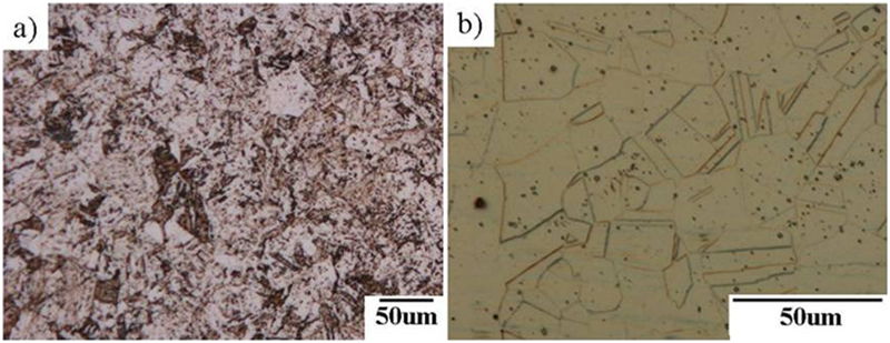
a F82H; b SUS 316
Figure 5 shows cross-sectional macrostructure of the friction stir lap welded SUS 316/F82H joints, which were produced under a constant rotation speed of 100 rev min−1 and a welding speed of 100 mm min−1; however, under a different applied load varied from 25 to 30 kN. It reveals that the welding temperature can thus be changed to control the shape of the joint interface by changing of the applied load. Figure 5a showed that the upper SUS 316 steel plate penetrated into the lower F82H steel side. A mixed structure in the SUS 316 side stir zone was thus formed because the yield strength of SUS 316 was higher than that of F82H at this welding temperature. Figure 5b shows that the joint interface is almost flat. The SUS 316 and F82H did not penetrated into each other because the yield strengths of these two materials are similar at this welding temperature. Figure 5c shows that the F82H penetrated into the SUS 316 side and therefore formed a mixed structure in the SUS 316 side stir zone because the yield strength of F82H is higher than that of SUS 316 at the welding temperature.
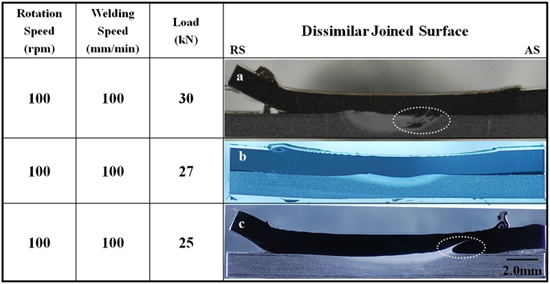
a mixed interface; b flat interface and c mixed interface
Figure 6 shows cross-sectional macrostructure of the friction stir lap welded F82H/SUS 316 joints, which were produced under a constant welding speed of 100 mm min−1 and an applied load 10 kN respectively. However, the rotation speed was varied from 100 to 400 rev min−1. Figure 6a shows that the SUS 316 penetrated into the F82H side. An SUS 316 particle band in the F82H side stir zone was formed because the yield strength of SUS 316 is higher than that of F82H at this welding temperature. Figure 6b shows that the SUS 316 still penetrated into the F82H side and formed a mixed structure in the F82H side stir zone because the yield strength of SUS 316 is higher than that of F82H at this welding temperature. Figure 6c shows that the dissimilar joint has a defect due to the insufficient material flow at this lower welding temperature. For the sake of comparison, the rotation speed and welding speed in Fig. 6d are the same as in Fig. 6c, but the load was increased to 18 kN in order to the increase welding temperature. As a result, Fig. 6d shows that the interface shape of the dissimilar welded joint is almost flat and that SUS 316 and F82H in the joint did not penetrate into each other because the yield strengths of SUS 316 and F82H are the same at the welding temperature. It reveals that, although the welding conditions of the friction stir lap welding for SUS 316 and F82H are different, the lap joint with same flat joint interface can be obtained due to the control of the welding temperature. Therefore, in this study, the microstructure and mechanical properties of the lap joints shown in Figs. 5b and 6d were compared, which both have a flat joint interface but were obtained under different welding condition.
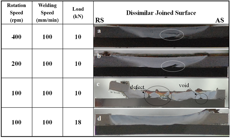
a mixed interface; b mixed interface; c defective interface and d flat interface
Microstructural evolution
Figure 7 shows the cross-sectional microstructure of the dissimilar friction stir lap welded F82H/SUS 316 and SUS 316/F82H joints. It revealed that the stir zones of these two kinds of joint can expand into the lower part of the steel sheets because the length of the probe was longer than the thickness of the upper steel plate. The microstructure of the joint interface in both lap welded joints showed that there was an obvious boundary line between the two different steel plates, no matter how the steel plates were overlapped. Along the joint interfaces, there do not have any welding defects or voids, as shown in Fig. 7a2 and b2. In addition, mixed microstructure or intermetallic compounds cannot be observed. In the stir zone of both lap welded joints, F82H side has a fine recrystallised ferrite microstructure due to the dynamic recrystallisation during the FSW process. However, the average grain size of the F82H steel in the SUS 316/F82H joint is larger than that of the F82H steel plate in the F82H/SUS 316 joint due to the lower cooling rate of the SUS 316/F82H joint than that of the F82H/SUS 316 joint. Therefore, the larger grain size is deduced to be caused by the extended grain growth stage at high temperature due to lower cooling rate. Figure 7a3 and b3 shows the microstructures of the stir zone on the F82H side of the two different joints respectively. Both microstructures consisted of grain refined and recrystallised ferrite, which had the same phase constitution as the base metal due to the low peak welding temperature of ∼710°C, lower than the AC1. Figure 7a4 and b4 shows the microstructures of the stir zone on the SUS 316 side of these two joints, which consisted of a fine equiaxed grain structure with an average grain size under 1 μm. The grain size is smaller than that of the typical friction stir welded austenite stainless steels (14·1 μm) because the present dissimilar joints were welded at a relatively lower welding temperature.22
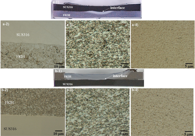
a1 Cross-sectional macrostructure, a2 OM images of joint interface, a3 microstructure of F82H and a4 microstructure of SUS 316 of lap FSW SUS 316/F82H joint; b1 cross-sectional macrostructure, b2 OM images of joint interface, b3 microstructure of F82H and b4 microstructure of SUS 316 of lap FSW F82H/SUS 316 joint
Figure 8 shows the energy dispersive x-ray spectroscopy line scan profile indicating the distribution of Cr and Ni elements across the joint interface between the SUS 316 and F82H steels in the lap welded SUS 316/F82H and F82H/SUS 316 joints. The line profiles reveal that the distribution of these elements are uniform and then changed sharply at the joint interface. There is no interdiffusion of element across the joint interface. It indicated that the mixed microstructure and intermetallic compounds were not formed by the chemical reaction in the dissimilar friction stir lap welded joints.
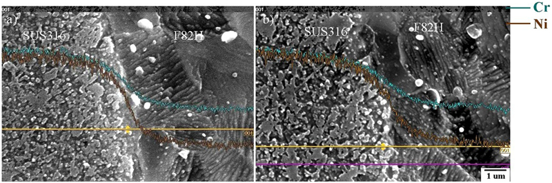
Energy dispersive x-ray spectroscopy line scan profile across joint interface of a lap SUS 316/F82H joint and b F82H/SUS 316 joint
The microstructural along the joint interface was further analysed by EBSD, and the results are shown in Fig. 9. Figure 9 shows the image quality map and phase map of the joint interfaces for the FSW lap SUS 316/F82H and F82H/SUS 316 joints respectively, which were welded at a rotation speed of 100 rev min−1 and welding speed of 100 mm min−1. For the SUS 316/F82H joint, F82H side along the interface consisted of grain refined ferrite with an average size of 3·5 μm. As for the F82H/SUS 316 joint, the F82H side along the interface consisted of grain refined ferrite with an average size of 0·8 μm. However, the SUS 316 sides along the interface have almost the same grain structure in both joints, which consisted of refined equiaxed austenite with an average size of 0·7 μm. These results clearly show that both welding conditions can create a grain refined microstructure of SUS 316 and F82H of the base metal due to the welding temperature lower than AC1. However, the grain size of the F82H side had a totally different distribution under the present welding conditions due to the different cooling rates, and the microstructure of grain refined F82H in Fig. 9a is bigger than that in Fig. 9b F82H grains.
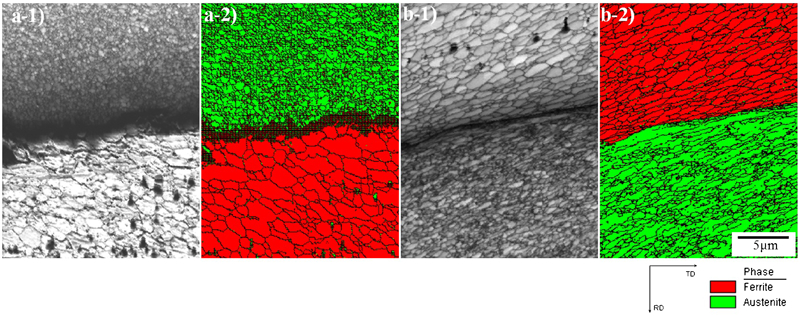
Figure 10a1 and b1 shows the TEM bright field images from the joint interface of the dissimilar FSW lap SUS 316/F82H and F82H/SUS 316 joint. It reveals that only refined ferrite and austenite phases were present along the interface, which can be confirmed from the corresponding selected area electron diffraction pattern shown in Fig. 10a2 and b2. No intermetallic compound can be detected. Therefore, these two kinds of steel plates can be friction stir lap welded without the formation of mixed microstructure or intermetallic compounds, despite that which steel plate was placed as the upper steel plate.
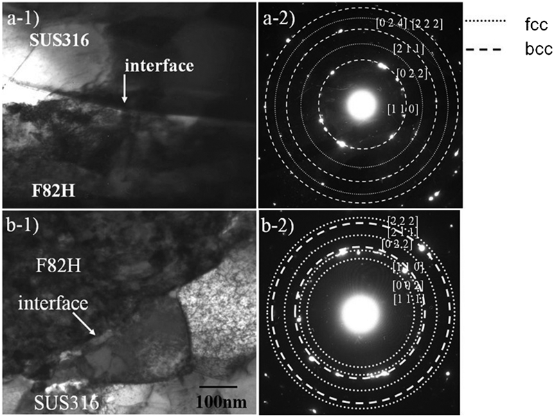
a1, a2 SUS 316/F82H joint; b1, b2 F82H/SUS 316 joint
Mechanical properties
Figure 11 shows the hardness profiles along the thickness of the stir zone of the dissimilar friction stir lap welded SUS 316/F82H and the F82H/SUS 316 joints. The zero position of the X-axial thus corresponds to the region near the surface of the upper plate. The hardness of the base metal of SUS 316 and F82H steel metal is ∼210 HV. As for the SUS 316/F82H joint, the stir zone of the upper SUS 316 plate has a hardness value of ∼310 HV along the plate thickness from the top to the joint interface, which is much higher than that of the base metal due to the refined austenite grains. The hardness in lower F82H plate is ∼250 HV within 0·5 mm from the joint interface. Then, the hardness decreases gradually along the thickness to ∼210 HV at the bottom of the lower plate.
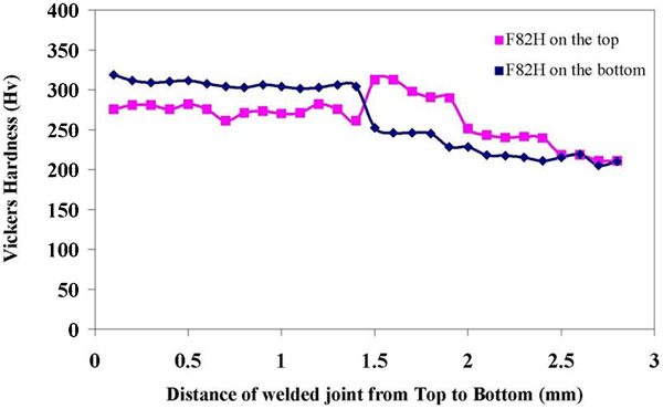
Hardness profiles of cross-sections of dissimilar friction stir lap welded SUS3 16/F82H joints
The hardness profiles for the F82H/SUS 316 joint show that the stir zone in the upper F82H steel plate has a constant hardness value of 270 HV because the welding was performed below AC1. The hardness in the lower SUS 316 plate is 320 HV within 0·5 mm from the interface due to the refined austenite grains, and the hardness then decreases to ∼210 HV at the bottom.
Figure 12 shows the fractured SUS 316/F82H and F82H/SUS 316 joints after shear tensile tests respectively. Both joints fractured at the F82H base metal and the dissimilar friction stir lap welded joints show the same strength as that of the F82H base metal.
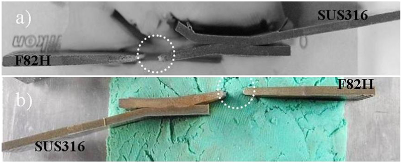
a SUS316/F82H joint and b F82H/SUS316 joint
Conclusions
In summary, the dissimilar materials of SUS 316 and F82H steel plates can be successfully joined by lap FSW technique, no matter which plates is place as the upper plates. This study clarified that the dissimilar friction stir lap welding of high melting point steels can be achieved without a mixed microstructure and intermetallic compounds by controlling the welding temperature.
When the dissimilar friction stir lap welding of F82H and SUS 316 was performed with the same yield strength, the interface shape is almost flat and the SUS 316 and F82H did not penetrate into each other. In this case, the joints have no mixed microstructure and intermetallic compounds and no diffusion occurred. Consequently, the dissimilar friction stir lap welding of F82H and SUS 316 is achieved, and the interface shape can be controlled by the welding conditions.
Footnotes
Acknowledgements
This work was supported by the Japan Atomic Energy Agency under the Joint Work contract no. 21K079. The authors wish to acknowledge the financial support of a Grant-in-Aid for Science Research from the Japan Society for the Promotion of Science and Technology of Japan, the Global COE Programs, a Grant-in-Aid for the Cooperative Research Project of Nationwide Joint-Use Research Institutes from the Ministry of Education, Sports, Culture, Science and Toray Science Foundation, and ISIJ Research Promotion Grant, and an Industry-University cooperative research project ‘Heterogeneous Structure Control: Towards Innovative Development of Metallic Structural Materials’ by JST agency.