
Abstract
Dissimilar materials, aluminium 2024-T3 and ultralow carbon steel, have been welded by a novel process called friction melt bonding. A finite element thermal model is developed to predict temperature cycles and to estimate the fusion pool geometry and the intermetallic bonding layer thickness. The total mechanical power input in pseudo-steady state is inferred from in situ measurements at the tool torque and rotational speed. Temperature dependent properties, including the latent heat of fusion, and proper contact conditions between the welded plates and the backing plate are included. Predicted temperatures are in agreement with the measurements at various distances from the weld centreline. Molten pool geometries and intermetallic thicknesses, whose control is crucial to insure good weld mechanical performances, are also in accordance with the experimental observations.
Introduction
To simultaneously meet requirements of lightness and crashworthiness, autobody design increasingly uses the combination of different materials, 1 where aluminium and steel are among the preferential choices. In this framework, friction melt bonding (FMB) is an innovative process inspired from friction stir welding (FSW) that allows to weld dissimilar materials in a lap joint configuration. 2 In FMB, a simple cylindrical tool rotates on top of the steel plate. The heat generated by friction and plastic deformation is transmitted by conduction to the aluminium plate (located underneath the steel plate) and melts it locally, causing the formation of a thin intermetallic (IM) layer (see Ref. 2 and Fig. 1). van der Rest et al. 2 performed a thorough review of all welding processes proposed to join aluminium and steel. DebRoy and Bhadeshia 3 have edited a compilation on dissimilar FSW and reported the importance of addressing the challenges of welding aluminium to steel. Friction melt bonding is of special interest to address these challenges since it takes advantage of the two main features specific to those welds, i.e. the highly different melting temperatures of the base materials and the fast formation of the Al–Fe IMs. The brittle IM layer thickness has been reported to have a direct influence on the mechanical properties of the weld. 4 Lap shear tests of Al2024–ultralow carbon (ULC) steel FMB welds have shown a good strength with fracture mostly in the steel base material. 2
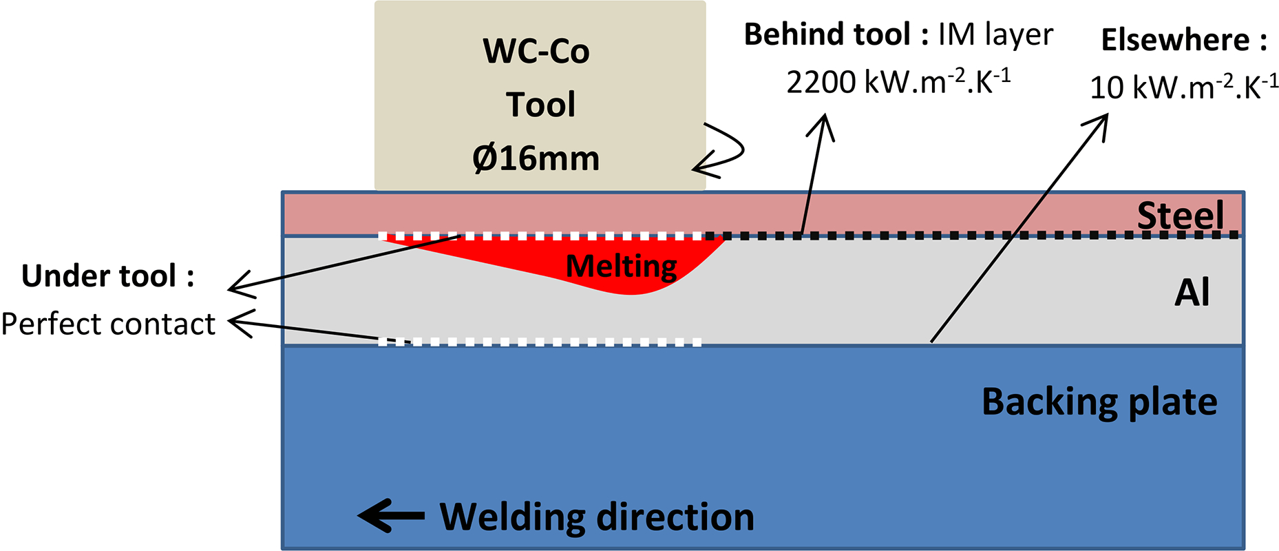
Schematic of FMB process and contact conditions between steel and aluminium alloy plates, and backing plate (not to scale)
He et al. 5 completed a recent and comprehensive review of the modelling of FSW. They suggested that starting from simple models is interesting for identifying the most dominant process parameters. While the heat source in FMB can be modelled similarly to FSW,4–7 FMB involves melting, which is not the case in the FSW process. De 8 developed a model for predicting the temperature field in resistance spot welding. He introduced the latent heat of fusion using an apparent specific heat between the solidus and liquidus temperatures. Deng 9 applied the same strategy to account for phase transformations in steel.
In the present study, a finite element model predicts the thermal field as a function of the welding parameters. The IM layer geometry can then be estimated by a kinetic growth model using the predicted thermal cycles. In a later stage, these models could be integrated in a larger modelling framework for predicting the weld mechanical performances based on the process parameters, as previously suggested for FSW.7, 10
Experimental
The base materials are ULC steel and aluminium 2024-T3 (see supplementary material 1 for their compositions) with thicknesses of 0.8 and 2 mm respectively. Sheets of both materials (250 × 80 mm) are clamped together on a high carbon steel backing plate with the ULC steel sheet on top (Fig. 1). To ensure a good contact between the sheets and favour heat transfer, the clamping system presses on the upper sheet at 15 mm from the weld centreline. The tool coming into contact with the ULC sheet is a flat ended cemented tungsten carbide (K20) cylinder, 16 mm in diameter. The tool does not wear out during the welding process.
Welds were carried out on a milling machine with a rotational speed of the tool of 2000 rev min− 1 and a backwards tilt angle of the tool of 0.5°. Three advancing speeds of the tool were tested: 200, 400 and 600 mm min− 1. Three welds were performed per condition.
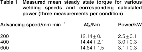
Ten type K thermocouples (0.5 mm in diameter) were embedded into the aluminium on the advancing and retreating sides. Each thermocouple was placed 1 mm deep into the aluminium plate and at 10, 12, 14, 16 and 19 mm from the weld centreline (see supplementary material 2). The tool torque was measured using a rotating dynamometer. The measured mean torques in steady state are reported in Table 1. Scanning electron microscopy (SEM) allowed the observation of the fusion zone and IM layer geometry.
Measured mean steady state torque for various welding speeds and corresponding calculated power (three measurements per condition)
Description of thermal model
Finite element geometry and thermal transfer to environment
Thermal finite element simulations are performed in a pseudo-stationary framework and consist in a stack of three layers (80 mm wide) representing the steel and aluminium plates and the backing plate (Fig. 1). Initially, room temperature (300 K) is imposed to the entire mesh. The top and bottom surfaces of the stack are subjected to convection (coefficient equal to 12 W m− 2 K− 1 for the upper steel surface and equal to 6 W m− 2 K− 1 for the bottom surface of the backing plate 11 ) and radiation (emissivity equal to 0.3). The model has a symmetry plane at the weld centreline; no difference is made between the advancing and retreating side. Such a difference could be introduced in the model by the insertion of a rotational material flow. 12 The mesh is composed of hexahedral elements with a higher density in the surroundings of the tool.
Thermal properties
High temperatures, sharp temperature gradients during the process and aluminium melting justify the use of temperature dependent thermal properties.8, 13 The ULC steel composition is very close to pure iron and hence its thermal properties, as provided by Tesfaye et al., 14 are used in the simulations.
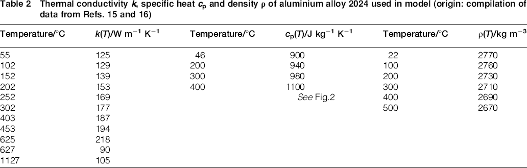
In the case of Al2024, the thermal properties measured in Ref. 15 are used up to the melting temperature (Table 2). Reference 15 also provides the fraction of liquid phase as a function of temperature (Fig. 2). The specific heat of aluminium is corrected to account for the extra energy required for melting (Fig. 2). The latent heat of melting (ΔHf = 389 kJ kg− 1) 16 is distributed between the solidus (510°C) and liquidus (600°C) temperatures, as suggested by De, 8 and the energy required for melting is assumed to be proportional to the rate of melting. The thermal conductivity of molten Al2024 is assumed to be identical to the value of pure liquid aluminium reported by Powell et al. 17 Some authors (e.g. Bonifaz and Richards 13 ) account for convection in the molten pool by an increased thermal conductivity. This is not performed in the present study as this would require identifying an extra free parameter.
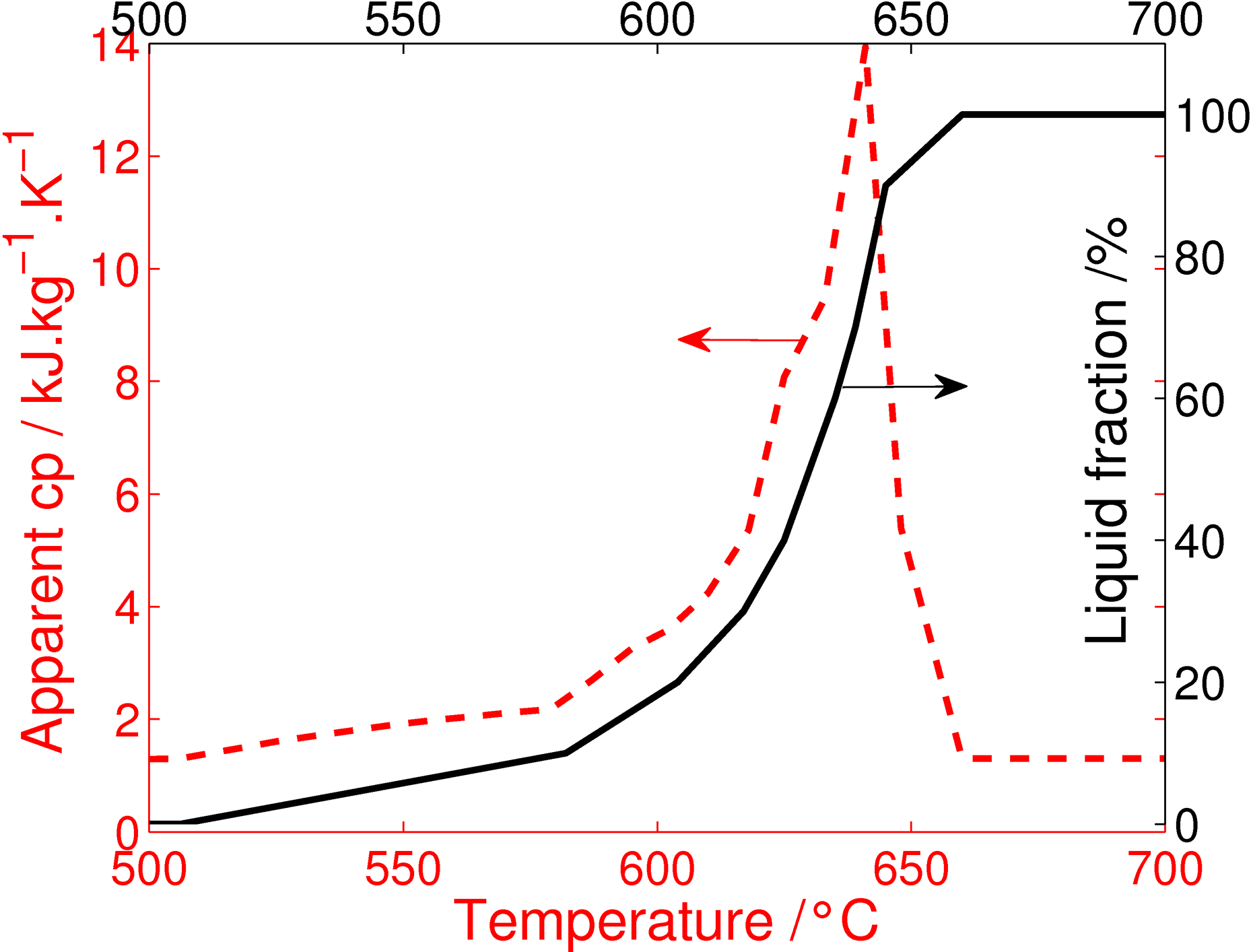
Evolution of apparent specific heat cp and liquid fraction 15 as function of temperature for aluminium alloy 2024, around melting temperatures
Temperatures in the high carbon steel backing plate are lower, and hence, the variation of its thermal properties with temperature is neglected. The values used are cp = 460 J kg− 1 K− 1, ρ = 7700 kg m− 3 and k = 47 W m− 1 K− 1. 18
Heat input and distribution
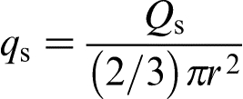
Heat is generated by a combination of both viscoplastic deformation of a small volume of steel under the tool Qv and frictional dissipation due to the relative motion between the workpiece and the tool Qs. Both contributions to the heat source are inferred from the measured torque Mz and the rotational speed ω (Table 1, equations (1) and (2)). The torque is found to be dependent on the tool advancing speed as reported for FSW.6, 19 The model assumes that all the power supplied by the machine P is transformed into heat. The power dissipation associated with the advancing force has been neglected. Heat loses through the tool are taken into account by an efficiency η = 0.90,6, 7 obtaining an effective power input value Pin


The volume heat source Qv is uniformly distributed in the steel upper sheet under the tool, in the entire thickness of the steel plate. The surface heat source qs (W m− 2) depends on the radial position as suggested by Refs. 6, 7, 21–22.
Thermal contact conditions
Assessing thermal contact conductance with precision is usually a complex problem as it can be pressure and temperature dependent.4, 9 In the present model, a constant conductance is associated to various zones (Fig. 1), as also proposed by Refs. 7 and 21. The values that are difficult to estimate physically are chosen in order to best fit the experimental cooling rate at a reference advancing speed of 400 mm min− 1. Below the tool, the solid–liquid contact of steel and aluminium and the contact between the aluminium and the backing plate are considered to be perfect due to the local high pressures. The contact in the welded region behind the tool and at the location of the IM layer is modelled by introducing a contact conductance of 2200 kW m− 2 K− 1. This corresponds to the thermal conductivity of the IM divided by the 5 μm thickness of that layer for the reference weld. The thermal conductivities of FeAl3 and Fe2Al5 are not provided in the literature, so a thermal conductivity of 11 W m− 1 K− 1 is used. This last value is given by Tarada et al. 24 for Fe/Al ratios between 45 and 53% and found to be only slightly depending on the Al fraction. Thermal gap conductances elsewhere are given a smaller value, i.e. 10 kW m− 2 K− 1.
Intermetallic growth model
The formation kinetics of the IM layer is calculated from the simulated thermal cycles. van der Rest et al.2 have observed and discussed the IM formation in the FMB process. On the aluminium side, the IM layer is FeAl3 and keeps a constant thickness ∼1 μm for all welding conditions. On the steel side, the IM layer is Fe2Al5 and presents a tongue-like morphology.2, 25 Its mean thickness decreases with increasing advancing speed. It is thus the growth of Fe2Al5 that controls the IM growth rate in the aluminium steel welded joints.
The model proposed by Kajihara et al.
25
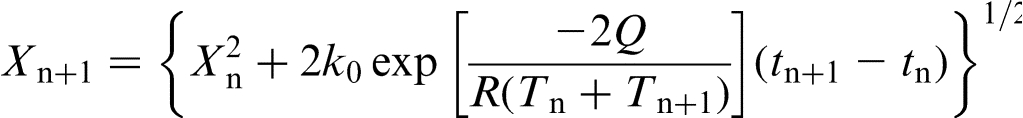
assumes that the IM growth follows a parabolic law and is proportional to the square root of the heating time. Anisothermal cycles require a temperature dependent growth rate that is described by an Arrhenius behaviour.
Results and discussion
Depth of molten pool
Using the SEM observations, the maximum vertical depth of the molten pool H has been measured and compared to the position of the predicted isotherms of 630°C corresponding to a liquid fraction of aluminium equal to 50% (Fig. 3a). Figure 3b shows that the depth of the molten pool significantly decreases when the advancing speed increases. This is well predicted by the model, which takes into account the variation of the power input with the advancing speed (Table 1). A weld performed at 800 mm min− 1 has been tested experimentally, but no joining occurred since aluminium did not melt at the interface with the steel plate. This is also well predicted by the model.
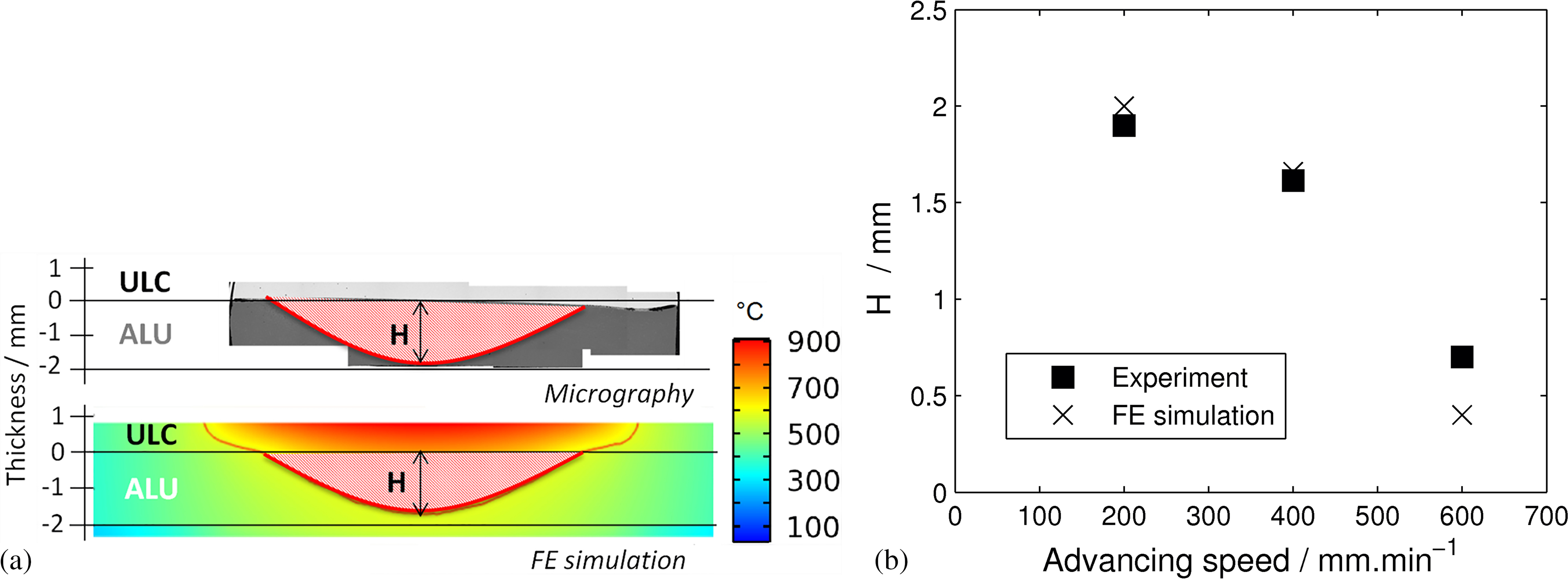
a definition of molten pool depth H on FE simulations at temperature corresponding to 50% liquid fraction and on micrograph for weld with advancing speed of 400 mm min− 1 and b comparison between measured and predicted depths for various advancing speeds
Moreover, van der Rest et al. 2 have shown that advancing speeds larger than 400 mm min− 1 may lead to some porosity in the aluminium due to a hot tearing phenomenon. To predict this effect, a mechanism based on the size of the molten pool is suggested. The deeper is the pool, the thinner is the remaining solid aluminium below. If this solid Al layer is thin enough, it will deform due the solidification shrinkage, lowering stresses in the semisolid zone. On the other hand, if it is too stiff to deform, the stresses in the mushy zone will be higher leading possibly to hot tearing. No porosities are found if the advancing speed is below 400 mm min− 1, corresponding to a molten pool representing 85% of the aluminium sheet thickness (Fig. 3b).
Thus, the simple model proposed here allows predicting the advancing speeds corresponding to the weld behaviour transitions, i.e. the appearance of hot tearing (>400 mm min− 1) and the advancing speed corresponding to the lack of Al melting (>800 mm min− 1). In addition, the present model allows estimating the cooling rates in the mushy zone, which are related to hot tearing (∼100 Ks− 1).
Thermal cycles
Fig. 4a shows that the advancing side is hotter than the retreating side as commonly reported for FSW. 6 The symmetry of the present model hides this fact. Figure 4b shows that the maximum temperature and cooling rates are well predicted for all welding conditions. Lower advancing speeds lead to higher temperatures and longer cycles increasing the size of the heat affected zone in the aluminium alloy. 7 Al2024 being a heat treatable alloy, the tb3 state in which the material is delivered leads to coarse S′(S) type precipitation for temperatures exceeding typically 250–300°C, depleting the heat affected zone of the nanostrengthening precipitates (Guinier–Preston–Bagaryatsky zones). 26 Reducing the time at high temperature is thus a good strategy to avoid excessive loss of the mechanical performances of the aluminium due to coarse S′(S) precipitation.
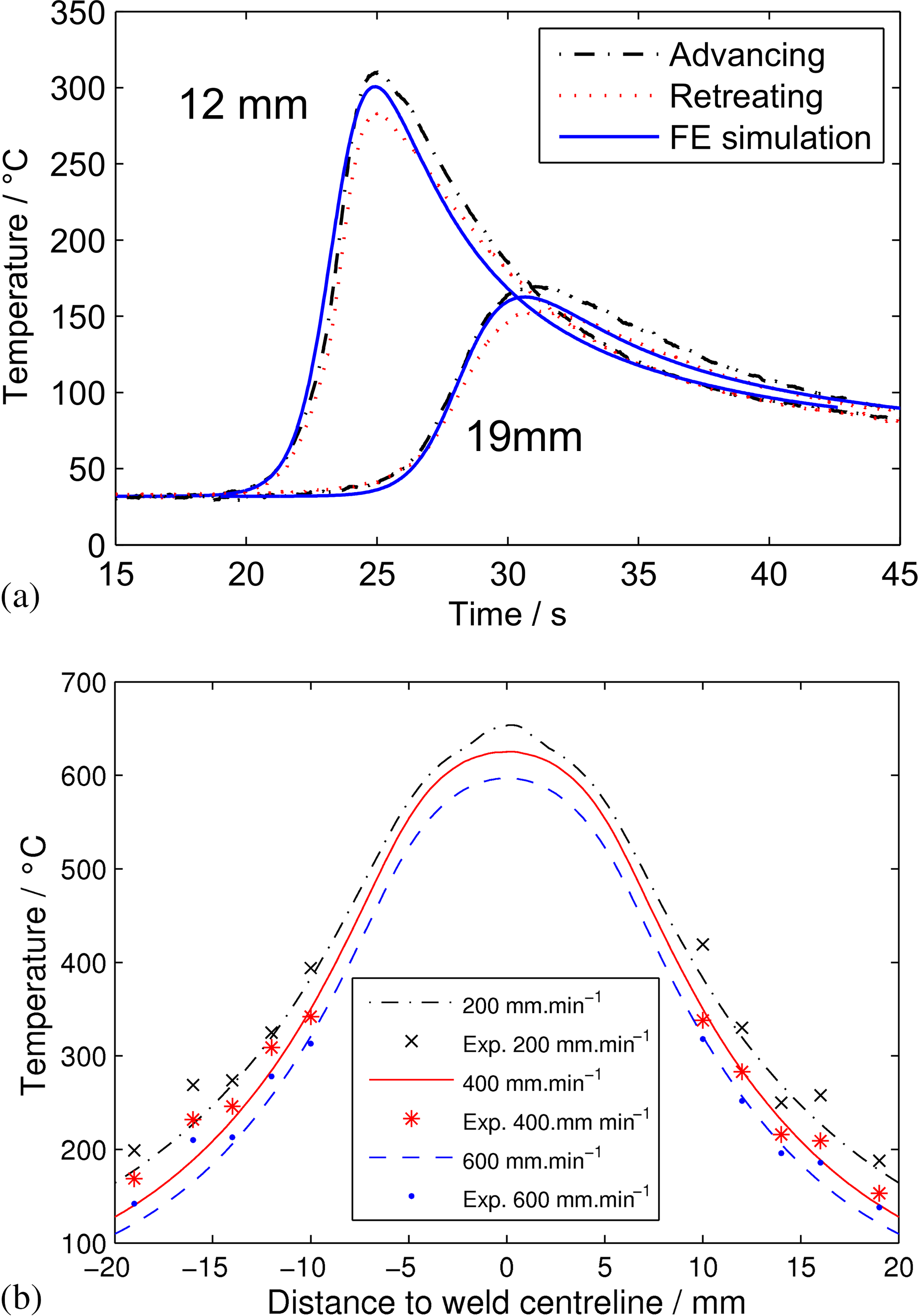
Comparison of measured and predicted a thermal cycles for advancing speed of 400 mm min− 1 and b maximum temperatures for three welding speeds; thermocouples in a are located at 12 and 19 mm from centreline (one on advancing side and one on retreating side)
Intermetallics thickness
Fig. 5 shows that, for an activation energy of Q = 200 kJ mol− 1 and a pre-exponential term k0 = 1.2 × 10− 2, the IM thickness at the weld centreline and the IM thickness distribution away from the centreline are fairly well predicted for the tested range of welding parameters. The fitted activation energy and pre-exponential term differ from the values found in the literature.27, 28 This could be the consequence of the difference in kinetics of growth between these isothermal experiments27–28 and the present anisothermal welds. The effect of heating and cooling rates, and probably local pressure rise during confined melting of aluminium, requires further investigation. Tanaka et al. 27 explained that the morphology of Fe2Al5 and the combination of different diffusional modes lead to a complex IM growth modelling. Das et al. 4 compared the strength of dissimilar IF steel/AA 6061 FSW lap welds. The strength of the weld is optimum for a thickness of 6.5 μm. The values measured in the present study are close to that favourable thickness (Fig. 5a).
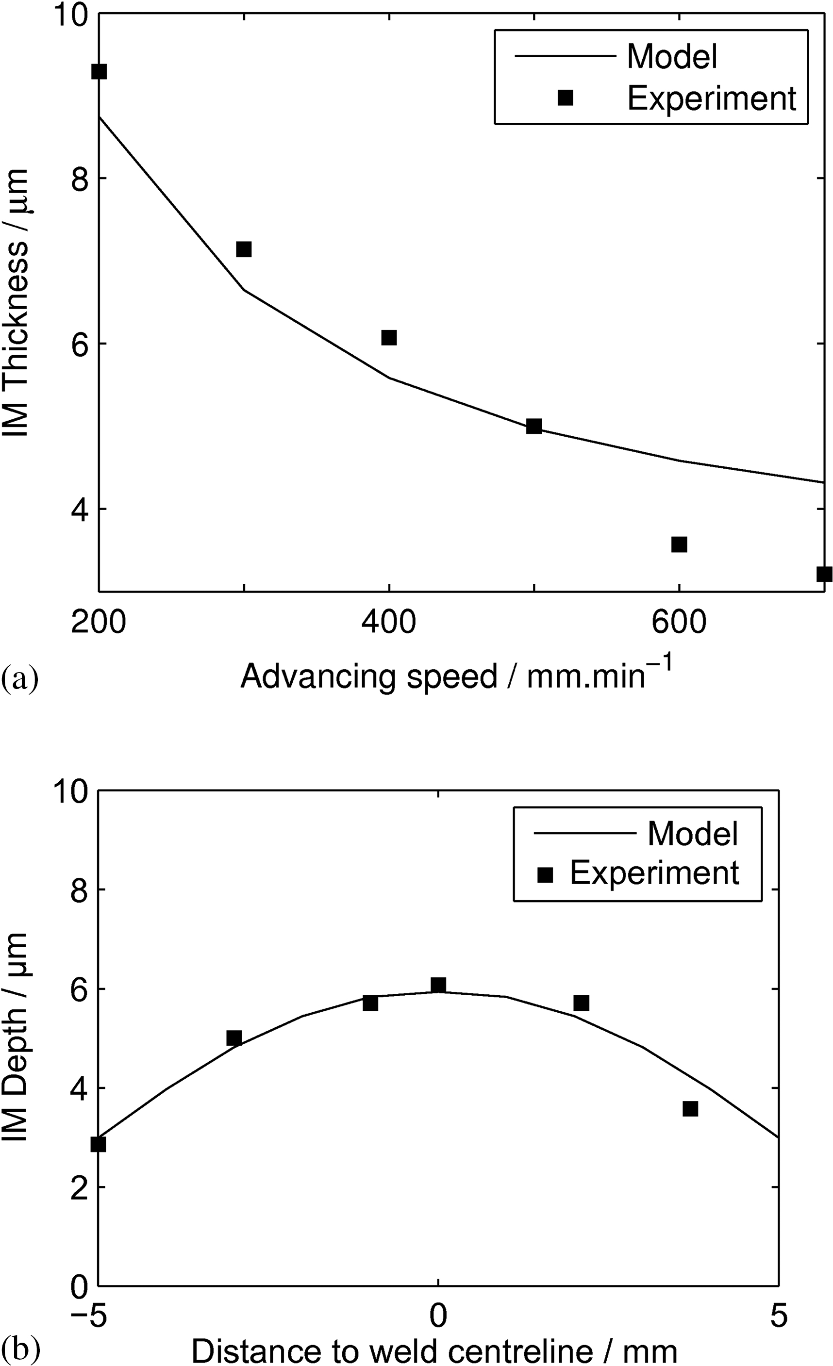
Comparison of measured and predicted intermetallic layer thicknesses a at centreline for several advancing speeds and b at various positions away from centreline for a weld performed at 400 mm min-1
Conclusions
A simple finite element model was developed to predict thermal cycles during FMB. The total heat input is inferred from torque measurements during welding. Thermal properties of the base materials are chosen to be temperature dependent, and the latent heat of melting of aluminium is taken into account through an apparent specific heat. The problem of thermal contact conductance is reduced to zones of constant values depending on the nature and conditions of the contact. In particular, the IM layer behind the tool at the steel/aluminium interface is given an appropriate thermal conduction. An IM growth model is chained to the thermal model. The results show the following.
The temperature cycles and aluminium weld pool geometry are correctly predicted for an Al2024–ULC steel combination.
The IM growth model correctly predicts the IM layer geometry.
The depth of the molten pool is correctly predicted by the model. It should be kept sufficiently large to avoid hot tearing, which can be reached with lower advancing speeds ( < 400 mm min− 1).
The present model also allows predicting the cooling rates in the mushy zone also related to hot tearing.
At the other extreme, with a too high advancing speed (>800 mm min− 1), not enough aluminium melts to insure correct bonding with the steel plate. No aluminium melting is indeed predicted by the model for that advancing speed.
The developed model could be used, in a later stage, as a tool to predict the best solution for maintaining sufficient aluminium melting but limiting the excessive IM growth by faster cooling. This could be carried out by tuning the experimental device, e.g. changing the backing plate material to tune heat pumping below the aluminium plate.
Acknowledgements
The authors acknowledge the financial support of the Interuniversity Attraction Poles Program from the Belgian State through the Belgian Policy Agency, contract no. IAP7/21 ‘INTEMATE’. N. Jiménez Mena and C. van der Rest are funded by a FRIA grant, Belgium. B. de Meester is acknowledged for his valuable comments.