
Abstract
In the present investigation, a microstructural characterisation of welds performed by resistance seam welding was carried out, with special focus on weld defect analysis. In order to perform a comparative weldability analysis, the welds were performed using similar welding procedures. Similar welds in aluminium (5754-H22) and zinc (Zintek) alloys, as well as dissimilar welds between galvanised steel and zinc, were studied. The defective aluminium welds were found to be characterised by important grain growth inside an inhomogeneous nugget and by the presence of important voids and cracks. The zinc welds showed a well defined nugget, but with porosities and some cracks. In the dissimilar steel–zinc welds, important macroscopic defects were observed. Microstructural analysis evidenced the occurrence of melting at the zinc side of the welds; meanwhile, no microstructural modifications could be observed for the steel side. Defect formation, as well as weld morphologies, was related to the variation in welding parameters.
Keywords
Introduction
Resistance seam welding (RSEW) is a joining process very similar to resistance spot welding (RSW), but enabling the fabrication of continuous lap welding between long plates. In fact, in RSEW, the welding electrodes are motor driven wheels rather than stationary bars. 1 Despite this, the main operative principles of the RSEW process are very similar to that of spot welding, i.e. the welding results from the transmission of electric current through the plates to be welded, which are overlapped between two electrodes. The electric current promotes heat generation, by Joule's effect, and localised melting of the base materials. The weld results from the solidification, under the pressure exerted by the electrodes, of the overlapped contacting surfaces. 2 As in any fusion welding process, some weld defects may be formed during both RSEW and RSW, which will influence the morphological and mechanical properties of the welded joints. Thickness reduction in the joining zone, 3 voids, 4 porosities 5 and cracks 6 are the most usually reported defects.
The welds produced by RSEW always display a thickness decrease, relative to the base materials, due to the pressure exerted by the electrodes over it. The higher the pressure applied, the greater the thickness reduction. Although the electrodes pressure is pointed as the most common cause for this defect, other variables can also have an indirect influence on it, such as the nature of the base materials and the heat generated. Actually, the thickness decrease can also be related to base materials shrinkage upon solidification. Under similar welding conditions (electrodes pressure and diameter), the softer the base material, the higher the thickness decrease. In the same way, the higher the heat input, the higher the thickness decrease due to softening. If the heat input is excessive, it can also lead to material projections out of the weld joint, which, in addition to the decrease in the weld thickness, also promotes poor surface finishing. 7
Other typical resistance seam weld defects are voids, porosities and cracks located in the fusion zone (FZ) and/or heat affected zone (HAZ). The formation of voids and porosities can be related to three factors: projections of material, shrinkage and gaseous inclusions. 8 Material projections, already referred above, are caused by an inadequate choice of electrodes and/or welding parameters, and can occur either at the electrode/plate contact interface or at the plate/plate interface. In the former case, surface quality and electrodes' life can be affected, and in the second case, the mechanical strength of the welds is adversely affected. Since the electric current needed is lower in steel welding than in aluminium welding, projections are more likely to occur in aluminium welding. 9
The gaseous inclusions are gas bubbles trapped inside the molten material, which, after solidification, give rise to porosities inside the FZ. The gaseous inclusions may result from hydrogen inclusions, volatilisation of alloying elements or other sources. The hydrogen inclusions are a common cause of porosities in welds, whenever this element is highly soluble in the base material. Since the hydrogen is present in the atmosphere and also in the sheets and electrodes, when they are wet, special care should be taken in order to avoid hydrogen inclusions. 10 The gaseous inclusions due to the volatilisation of elements, on the other hand, are restricted to the base materials that contain volatile alloy elements. During welding, due to the high heat input in the FZ, these elements may evaporate, leading to the appearance of gaseous inclusions. Other sources of gas inclusions can be the burning of lubricants and organic elements when the plate surfaces are not properly cleaned. Finally, the porosities associated with solidification shrinkage are located in the zones of the weld that are the last to solidify. These shrinkage porosities are smaller than that resulting from gaseous inclusions. However, these two phenomena may occur simultaneously combining each other and giving rise to bigger pores.7, 11
The presence of cracks in resistance seam welds results from some well known weld cracking mechanisms 12 such as hot cracking. Hot cracking may occur in two different ways: solidification and liquation. While the first one occurs in the FZ, the second one is characteristic of the HAZ. 13 As the name indicates, solidification cracking is due to base material shrinkage during the liquid to solid transition. Hot cracking in the HAZ, which occurs during heating, also results from the segregation of low melting point phases to the grain boundaries and thermal shrinkage stresses.8, 14
In the literature, it is possible to find a large number of works addressing similar RSW of a large range of base materials such as aluminium, 15 magnesium, 16 steel 17 and titanium, 18 and dissimilar such as steel/steel, 19 steel/Al, 20 Al/Mg 21 and steel/Mg. 22 However, in which concerns to RSEW, the information available is much scarcer. In the present work, the main defects in similar welds of aluminium (5754-H22) and zinc (Zintek) alloys, and dissimilar galvanised steel–zinc welds, produced by RSEW, are identified and its formation correlated with base material characteristics and welding parameters.
Experimental
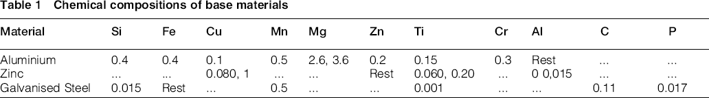
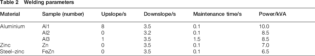
Similar welds between 1 mm thick plates of aluminium (5754-H22) and zinc (Zintek) alloys, as well as dissimilar welds between 0.85 mm galvanised steel plates and 1 mm thick zinc plates, were performed in the current work. The base materials' nominal chemical compositions are shown in Table 1. The welding parameters used are shown in Table 2. As illustrated in Fig. 1, the upslope, downslope and maintenance parameters shown in Table 2 define the periodicity of the current, as well as the heating and cooling rates in each current cycle.
Chemical compositions of base materials
Welding parameters
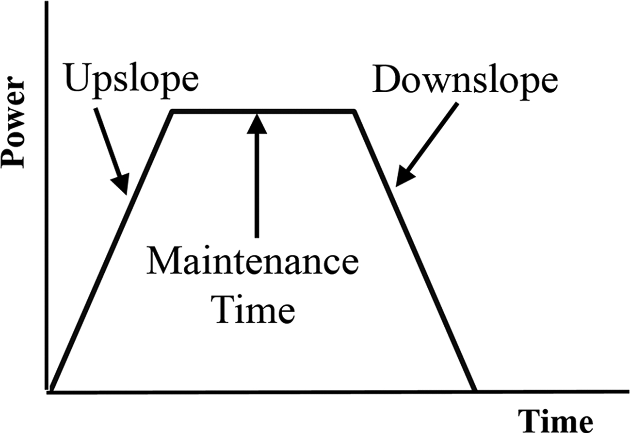
Scheme of welding parameters
Transverse and longitudinal sections of the welds were prepared according to standard metallographic practice and etched with modified Poulton's (aluminium), zinc etchant (zinc) and nital (galvanised steel) in order to enable the identification of the different weld zones. The reagent compositions are shown in Table 3. Metallographic analysis was performed using an optical microscope Leica DM 4000 M LED. Scanning electron microscopy/energy dispersive X-ray spectroscopy (SEM/EDS) was performed in the cross-section of one of the welds using a Philips XL30 SE.
Etchant compositions: modified Poulton's, zinc etchant and nital
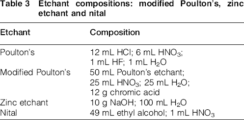
Figure 2 schematises the welding current pulses for the three base metals. In Fig. 2a, where the aluminium parameters are shown, it can be seen that the Al2 and Al3 welds were performed with the same power, as opposed to the Al1 weld, which was produced using higher power values. However, the figure also shows that the Al1 weld was performed using longer current pulsation periods than those used in Al3 and Al2 welding, resulting in a lower heat input frequency. Figure 2b illustrates the welding parameters for the similar Zn and the dissimilar FeZn welds. Through the figure, it can be inferred that the welding parameters used were similar, being only used a slightly lower power value in the FeZn welding. Moreover, comparing these two welds with the Al2 weld, it can be concluded that the only difference is the fact that the latest joint was performed with a higher power value. In any case, the power used was adapted in order to obtain welds without any macroscopic discontinuity.
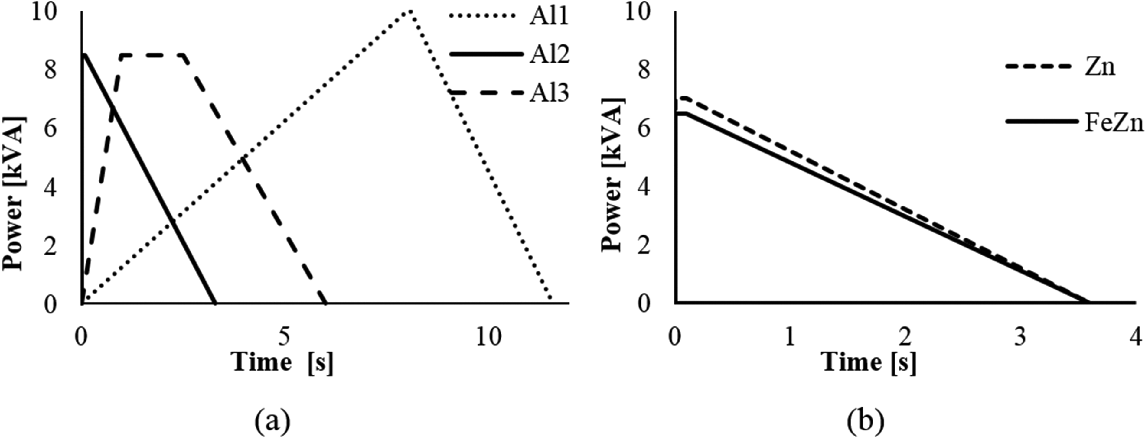
a similar welding of aluminium; b similar welding of zinc and dissimilar welding of galvanised steel–zinc
Results and discussion
Microstructural analysis of similar aluminium welds
Results of the longitudinal cross-section analysis of the Al1 weld are illustrated in Fig. 3. Specifically, a macrograph of the whole section is displayed in Fig. 3a, and magnified pictures of the lap interface are shown in Fig. 3b and c. From Fig. 3a, it can be observed that the longitudinal section of this weld has an unsymmetrical morphology, i.e. one of the weld surfaces is undulated, whereas the other is smooth. The surface undulations seem to be periodic, which can be associated with the periodicity of the current shown in Fig. 2. The discontinuous black line at the middle of the joint (Fig. 3b and c), suggesting non-continuous joining across the weld, can also be associated with the periodicity of the current, i.e. when a current peak was reached, the heat was sufficient to promote the joining. No joining occurred during the up- and downslope of the current. It should also be noted that the appearance of surface undulations exclusively in one of the weld sides may be related to differences in electrodes surface quality, i.e. one of the electrodes had higher wear and/or soiling than the other.
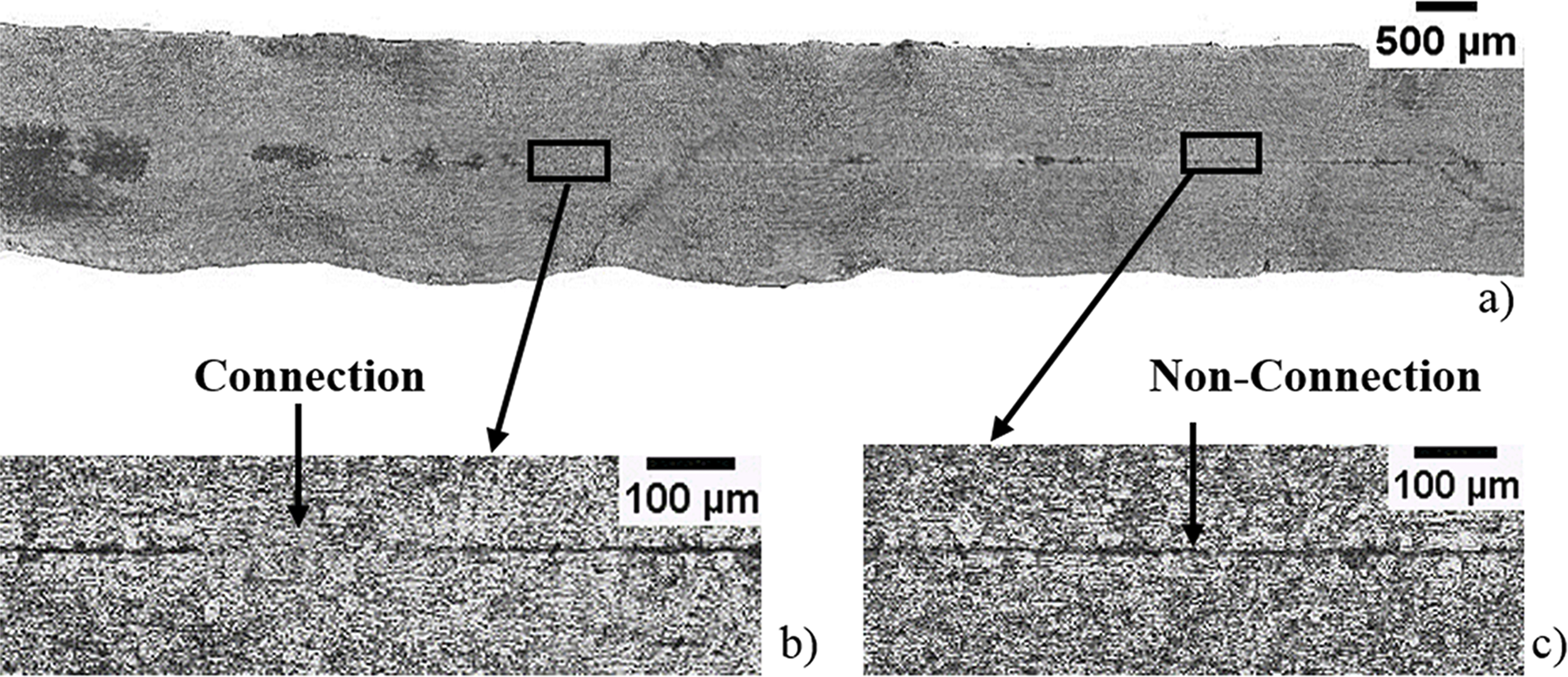
a longitudinal section; b welded zone; c non-welded zone
A transverse cross-section macrograph of the Al1 weld (Fig. 4a) as well as micrographs of specific cross-section zones, namely, base metal (Fig. 4b), HAZ (Fig. 4c and e) and FZ (Fig. 4d), are now shown in Fig. 4. Comparing Fig. 4b and c, it can be concluded that grain growth relative to the base material occurred in the HAZ. Moreover, some evidence of melting is discernible in the FZ micrograph shown in Fig. 4d. Actually, although well defined dendritic structures are not clearly observed, the extensive porosity and cracking noticed in this zone points to melting during welding. However, as illustrated in the picture, the solidification indicative structures are restricted to a very small region of the FZ, i.e. the welded materials interface, suggesting a very localised volume of aluminium being melted during welding. The analysis of the transverse cross-section also reveals the presence of cracks following the contours of HAZ grain boundaries (Fig. 4e). This crack morphology in the HAZ is characteristic of liquation cracking mechanisms. Liquation cracking results from the segregation to the grain boundaries of low melting point elements/compounds, being very sensitive to base alloy chemistry.13, 14, 23–25 Actually, the effect of Si, Cu, Mg and Mg2Si content on aluminium alloys hot cracking sensitivity is well documented in the literature through crack sensitivity curves,12, 13 which show that the susceptibility to hot cracking increases, with the increase in alloys content, until a maximum is reached, and then falls down to relatively low levels. In the case of Al–Mg binary 26 system (5xxx series of alloys), the hot cracking sensitivity reaches the maximum for an Mg content of 1.2%, becoming very small for Mg contents higher than 5%. According to Table 1, the Mg content of the AA 5754 varies between 2.6 and 3.6%, which is still inside the high cracking sensitivity range, explaining the occurrence of the liquation cracking during RSEW. Liquation cracking can be avoided through a careful selection of the alloy composition and/or process parameters. The faster the welding speed, the faster the cooling rate and the less time the weld will be in the hot cracking temperature range.

a transversal section; b BM; c grain growth in HAZ; d pores and cracking in FZ; e liquation cracking in HAZ
It is also important to stress that the thickness reduction in the nugget of the Al1 welds did not exceed 8% of both plates thickness.
Figure 5 illustrates the longitudinal cross-section of the Al2 weld as well as two transverse cross-sections macrographs (Fig. 5b and c) corresponding to two distinct sections in Fig. 5a. Micrographs of specific transverse cross-section regions (Fig. 5d and e) are also shown in the figure. As opposed to that registered for the Al1 weld, macrocavities were found to be present in the nugget of the Al2 weld, as a result of material projections, being periodically distributed along its longitudinal section, as shown in Fig. 5a. Like the periodicity of the Al1 weld surface undulations, the periodic distribution of Al2 weld cavities may also be related to the welding current periodicity, i.e. each section of cavities corresponds to a current peak. Furthermore, it should be noted that, similar to the previous phenomenon, cavities formation was also found to occur exclusively in one of the weld sides (Fig. 5a), which, as referred above, results from differences in electrodes surface quality.
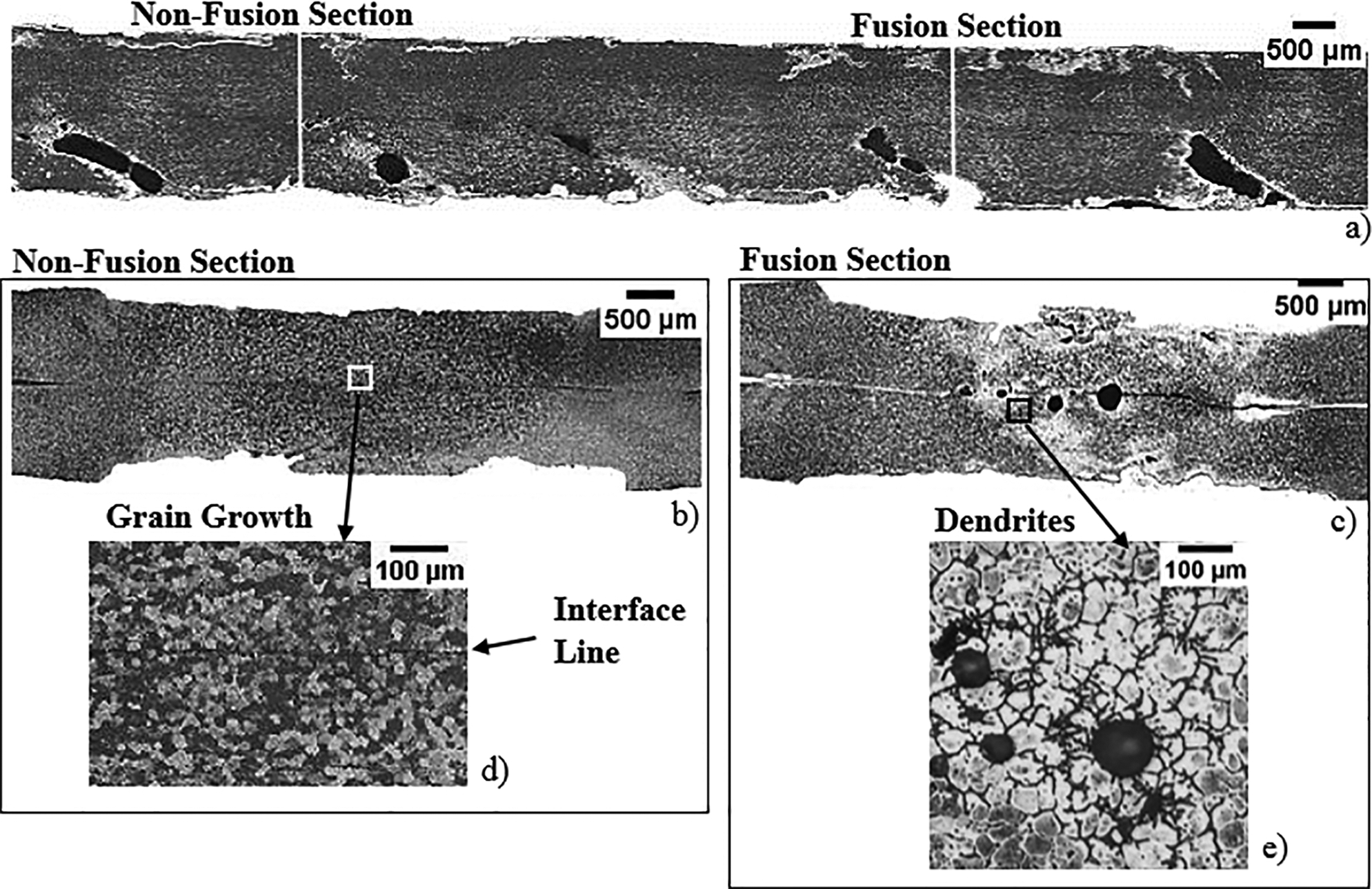
a longitudinal section; b, c transverse sections at locations ‘non-fusion section’ and ‘fusion section’ in a respectively; d magnification of grain growth in b; e magnification of dendrites in c
Important differences can be noticed by comparing the transverse cross-section macrographs of the Al2 weld (Fig. 5b and c). Actually, while no solidification structures were observed in the section illustrated in Fig. 5b, being only possible to notice important grain growth as well as a discontinuous dark line coincident with the initial interface of both plates (Fig. 5d ), dendritic structures were identified in the cross-section shown in Fig. 5c. These structures, as well as the presence of some scattered solidification defects (porosities), are clearly discernible in the micrograph illustrated in Fig. 5e. However, it should be noted that the dendritic structures were found to be present only in restricted areas of the cross-section. Actually, as illustrated in Fig. 5c, a heterogeneous microstructure composed of FZ and HAZ characteristic structures was observed throughout the entire thickness of the transverse section. Unlike the FZ, the HAZ is characterised by a coarse grain structure resulting from the high temperatures experienced during the process.
Longitudinal and transverse cross-sections macrographs of the Al3 weld are illustrated in Fig. 6a and b respectively. Micrographs registered in specific regions of the transverse section (Fig. 6c–e) are also shown in the figure. From Fig. 6a, it is possible to observe large number of cavities and porosities almost homogeneously distributed over the longitudinal section of the weld. In the same way, in the transverse cross-section shown in Fig. 6b, melting indicative microstructures can also be seen throughout the nugget, enabling to conclude that some of the larger cavities may result from material projections. On the other hand, the smaller pores visible in the central zone may be associated with material shrinkage upon solidification, to magnesium and zinc gaseous inclusions (volatile elements) and to the high hydrogen solubility of the aluminium alloy.11, 27 Besides the cavities and pores, this weld also displayed solidification cracks in the molten material areas (Fig. 6e) and important grain growth in the HAZ, which can be noticed by comparing Fig. 6c and d. Similar to that registered for the Al1 weld, liquation cracking was found to occur in some regions of the HAZ (Fig. 6e).

a longitudinal section; b transversal section; c BM; d HAZ; e liquation and solidification cracking
Important thickness reduction after welding can be noticed by comparing the thickness of the transverse cross-sections of samples Al2 (Fig. 5b and c) and Al3 (Fig. 6b) with the initial thickness of base material plates. However, unlike in the Al1 weld, the thickness reduction noticed in the Al2 and Al3 welds cannot be exclusively associated with the pressure exerted by the electrodes. Actually, it can also be related to the occurrence of material projections, which conducted to the formation of very irregular weld surfaces and non-uniform thickness reduction across the weld length.
Comparing these three aluminium welds, it can be concluded that the Al1 weld was performed under a lower heat input condition than Al2 and Al3 welds. According to the welding parameters analysis, previously described in the experimental procedure, this is due to the longer current pulsation period used in Al1 welding. The use of low heat input conditions enabled to reduce the formation of defects such as pores, voids and solidification cracking, but was not sufficient to avoid liquation cracking in the HAZ. The joining between the plates was also not continuous.
Microstructural analysis of similar zinc welds
Longitudinal (Fig. 7a) and transverse (Fig. 7b) cross-sections macrographs of the Zn weld are displayed in Fig. 7. Micrographs registered in specific regions of the transverse section (Fig. 7c–h) are also illustrated in the figure. The longitudinal section macrograph shows a homogeneous weld morphology, all along the weld length, as well as a small overlap between successive weld nuggets, which is naturally related to the periodicity of the current (Fig. 7a). Unlike to that observed for the aluminium welds, no remnants of the plates interface can be observed in this picture, which proves that there was continuous melting all across the interface.
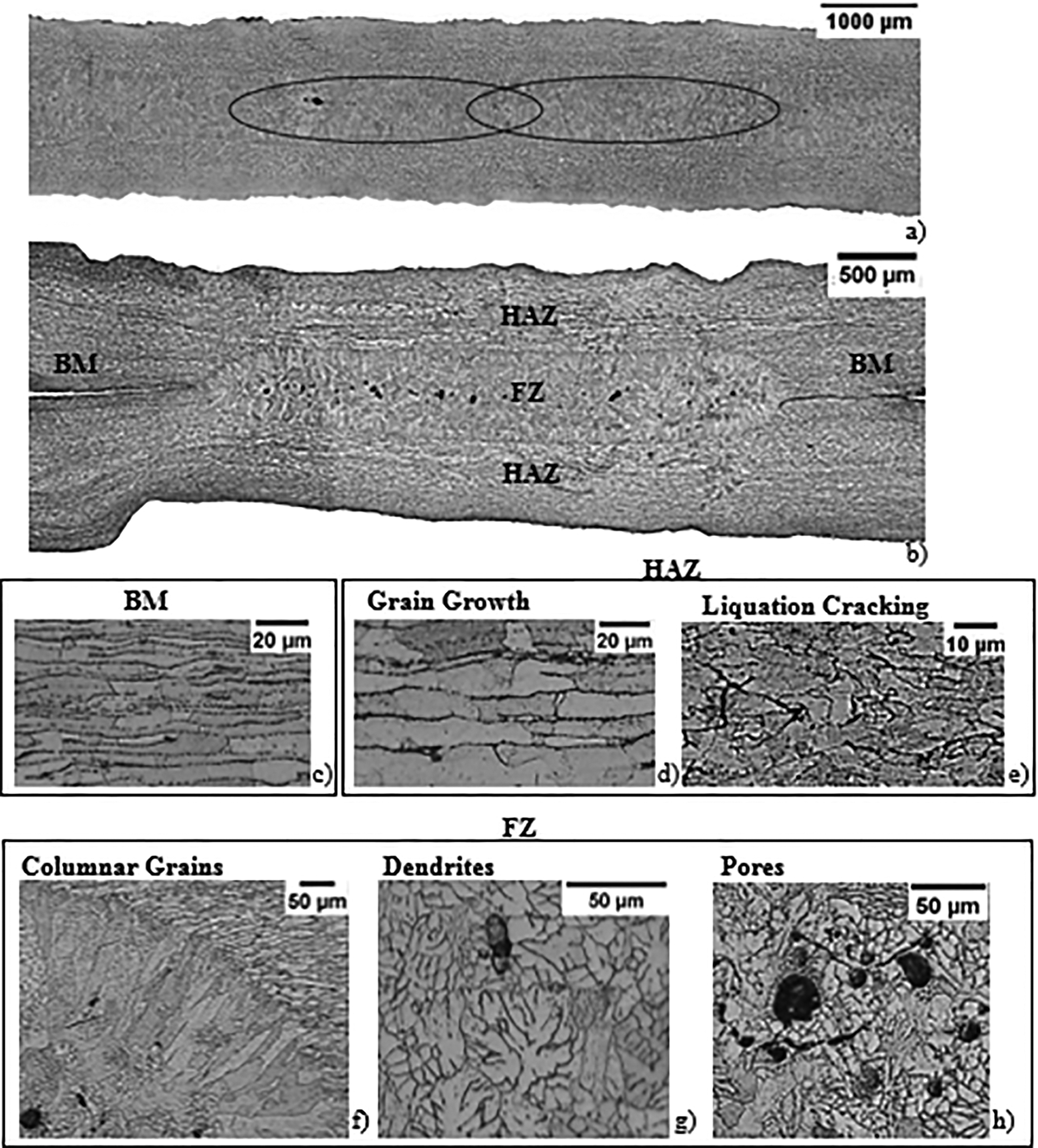
a longitudinal section; b transversal section; c BM; d grain growth in HAZ; e liquation cracking in HAZ; f columnar grains; g dendrites; h pores
The three characteristic weld zones (BM, HAZ and FZ) can be easily distinguished in the transverse cross-section of the Zn weld (Fig. 7b). From the BM micrograph shown in Fig. 7c, it is possible to conclude that the BM consisted of elongated grains, aligned with the rolling direction. Important grain growth in the HAZ can be noticed by comparing BM and HAZ microstructures in Fig. 7c and d. However, some cracks can also be observed in the HAZ (Fig. 7e), which can be associated with liquation cracking mechanisms, i.e. with the segregation of low melting point elements or compounds to the grain boundaries. In turn, the FZ, which corresponds to the whole nugget area, can be seen at the centre of Fig. 7b. The microstructure illustrated in Fig. 7f corresponds to the outer part of the nugget, showing the formation of columnar grains, aligned with the cooling direction of the weld. The dimension and distribution of the columnar grains around the nugget are uniform, enabling to conclude that heat dissipation during weld cooling was uniform. Also in the FZ, dendrites (Fig. 7g) and equiaxial grains can be observed, the latter ones being found at the nugget/HAZ interface. As illustrated in Fig. 7h, the centre of the nugget contains several pores, which, due to their small size and localisation, can be associated with material shrinkage upon solidification. The formation of columnar grains is naturally associated to the steep thermal gradient at the weld/base material boundary. However, the cooling rate, which is very high near the periphery of the nugget, decreases towards the centre of the weld, where it reaches minimum values. Formation of equiaxed grains takes place in this zone of the weld where the thermal gradients become insignificant.7, 28
Depending on the application to which this material will be subjected, a greater overlap between successive weld nuggets may be required, in order to confer a better mechanical resistance to the weld. Additionally, the formation of shrinkage porosities can be reduced through a controlled increase in electrodes pressure. On the other hand, hot cracking can only be avoided through a careful control of alloy composition. 13
Microstructural analysis of dissimilar steel–zinc welds
Figure 8 illustrates a longitudinal cross-section, before etching, and a transverse cross-section, after etching, of the FeZn weld. In the longitudinal cross-section of Fig. 8a, the interface of both base materials can be clearly observed, with a high density of large cavities and pores distributed along it. However, these defects are not visible in the transverse cross-section of Fig. 8b, where a strong thickness reduction in the zinc side of the weld can be observed, resulting from the sticking of this material to the electrode. The SEM detail of the transverse cross-section macrograph shown in Fig. 8c clearly illustrates the formation of microstructural solidification features only at the zinc side of the weld nugget. Effectively, no microstructural changes, relative to the initial base material structure, were registered in the steel side, as can be observed in Fig. 8d and e.
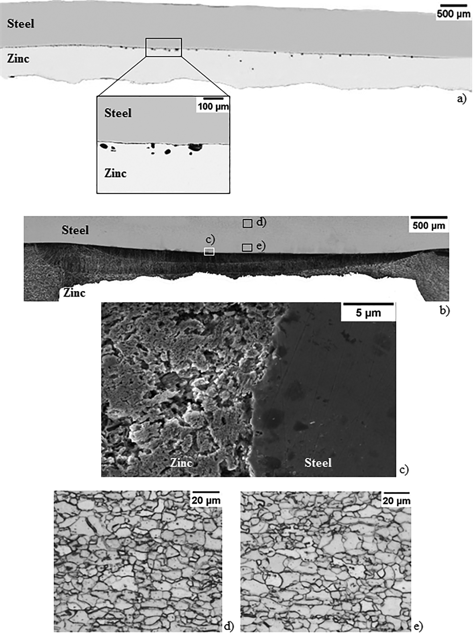
a longitudinal section before etching; b transversal section after etching; c SEM image of transversal section; d, e magnifications of galvanised steel microstructure
Comparing to the similar zinc welds, the welding parameters used to perform the dissimilar welds only differ in the power used, which was lower (Fig. 2b). However, according to Liu et al., 29 the differences in electrical resistivity between the steel and the zinc base materials had a strong influence on heat distribution inside the weld area. Owing to the higher resistivity of the steel, the heat generation by Joule effect was higher at the steel side of the weld. In this way, comparing to what happens in similar zinc welding, it can be inferred that the steel side of the dissimilar FeZn joint worked as an additional heat source to the zinc, which, as referred above, was melted during welding. Actually, as the melting temperature of the steel is much higher than that of the zinc alloy,30, 31 fusion exclusively occurred at the zinc side of the weld. Moreover, Liu et al., 29 in a study on dissimilar RSW of steel and magnesium, concluded that the welding resulted from the solidification of the zinc coating of the steel plates, which was found to melt at the sheets' interface. Since in current study one of the welded materials was zinc, joining by a similar mechanism can be assumed.
Conclusions
In the current work, similar welds in zinc and aluminium and a dissimilar weld in steel–zinc were analysed. The microscopic inspection of the welds revealed the presence of voids, porosities and cracks, for all the similar welds, independently of the base material. Meanwhile, the presence of large voids was associated with the projection of material from the weld seam during joining, the presence of porosities was associated with gas inclusions, alloy element volatilisation and solidification shrinkage. Solidification and liquation cracking mechanisms were also found to be responsible for large crack formation inside the FZ and HAZ respectively. For the aluminium alloy, a close relation between weld current pulsation and weld morphology was found, i.e. longer current pulsation periods enabled to reduce the incidence of high heat input related defects, such as material projections and solidification cracking.
For the dissimilar steel–zinc welds a large influence of the asymmetry in heat generation and dissipation on weld morphology was found. Meanwhile, no fusion, or even microstructural changes, was reported for the steel side of the weld; the occurrence of fusion and voids was reported in the zinc side. Actually, large quantities of zinc were removed from the weld seam due to excessive heat input from the steel side of the joint to the zinc side.
Acknowledgements
This research work is sponsored by national funds from the Portuguese Foundation for Science and Technology (FCT) via project no. PEst-C/EME/UI0285/2013 and by FEDER funds through the program COMPETE – Programa Operacional Factores de Com-petitividade, under project no. CENTRO-07-0224-FEDER-002001(MT4MOBI). One of the authors, C. Leitão, is supported by the Portuguese Foundation for Science and Technology through SFRH/BPD/93685/2013 fellowship. All supports are gratefully acknowledged.