
Abstract
This study compared the mechanical and microstructural properties produced during friction stir welding of S275 structural steel in air and underwater. Post-weld tests assessed the tensile strength, microhardness, distortion, Charpy impact toughness and fatigue performance in each case. The study showed that there was no significant difference in the strength, hardness or fatigue life of the air and underwater specimens. However, Charpy impact toughness was shown to decrease for the underwater specimens and was attributed to the presence of a slightly less angular grain structure than the samples welded in air. Reduced angular and longitudinal distortion was observed in the underwater welded plate compared to the plate welded in air.
Introduction
Friction stir welding (FSW) is a thermomechanical process in which two metals are joined together in the solid state to produce a high integrity, high quality joint.1, 2 Compared with conventional arc welding processes, there are a number of benefits including low distortion, minimal chemical segregation, enhanced strength and no detrimental effects to hardness due to grain refinement in the stir zone.3–6
Although the process has reached a stage of technical maturity for the ‘light alloys’, its application to metals such as steel, nickel and titanium has been slower to develop due to the severe loads and temperatures that the tool experiences during the welding process.7, 8 Tool design and the development of advanced materials for FSW of steel have therefore become a significant area of research in recent years, focusing specifically on improving tool lifespan. 9 This is the key to the future economic viability of the process. Perrett et al. 10 investigated FSW of industrial steels using two different tool materials: polycrystalline boron nitride (pcBN) and a W-Re/pcBN composite. In both cases, welds in excess of 40 m were completed without tool probe failure or any signs of weld defects. In addition to this, Sorensen 11 studied the wear and fracture sensitivity of three grades of pcBN tools and obtained a tool life of ∼60 m when welding structural steel.
The welding parameters in FSW include tool traverse speed, rotational speed, vertical force and traverse force. It has been reported that, by varying these parameters, the microstructural and mechanical properties can be precisely controlled, allowing for a repeatable, fully autonomous joining process, which produces almost defect free welds. 12 Fujii et al. 13 studied the effect of welding speed using three types of carbon steel: interstitial free steel, S12C (0.12 wt-%C) and S35C (0.34 wt-%C). In each case, the strength of the joint increased with increasing welding speed, with the exception of the S35C steel, which peaked at 200 mm min− 1. Hardness was also measured as a function of welding speed, and the following results were obtained: the interstitial free steel showed no significant gain in hardness, the S12C steel showed a linear increase in hardness and the S35C steel peaked again at 200 mm min− 1. The results were explained by considering the relationship between the peak temperature and the A1 or A3 point on the iron–carbon phase diagram. When FSW is performed in the ferrite–austenite two-phase region, the microstructure is refined, and the highest strength is achieved. Lakshminarayanan and Balasubramanian 14 also reported increases in strength and hardness during FSW of 409M ferritic stainless steel, where the coarse ferrite grains in the base material were converted to a very fine duplex structure consisting of ferrite and martensite.
To date, research into the subject of underwater FSW has been limited. Liu et al. 15 performed a study that determined the effect of welding speed on the microstructures and mechanical properties produced when welding 2219 aluminium alloy underwater. The results showed a significant increase in the tensile strength of the underwater joint in comparison with arc welds in the same material, which was attributed to the increased cooling rate preventing the deterioration of strengthening precipitates. Given the increasing interest in FSW for subsea and shipbuilding applications, it is essential that further research be completed to assess the feasibility of underwater FSW for steels. Some limited work has been carried out on steel.16, 17 The work 16 on quench and tempered HY80 steel, although very limited, highlighted that the wet stir zone and thermomechanically affected zone (TMAZ) had smaller grains than the dry stir zone and the base material; there were no significant issues with microhardness. The increases in microhardness were 52 and 70% for the dry and the wet stir respectively.
The present study reports on the comparison between the mechanical and microstructural properties produced in S275 structural steel when friction stir welded in air and underwater.
Experimental
S275 hot rolled structural steel was used in this study and was supplied in the form of plates measuring 2000 × 200 × 6 mm (length × width × thickness). The chemical composition of the plates was 0.12C–0.25Si–0.84Mn–0.007S–0.017P–0.007Ni–0.032Al. The yield and tensile strengths of the plate are 353 and 509 N mm− 2, respectively, and the elongation was 32.4%.
The S275 steel plates were welded with no milling of their mating edges, and no removal of the surface scale or primer. Double sided friction stir welds were created in both the air and underwater conditions using the hybrid WRe–pcBN, Q70 (70 vol.-%cBN) FSW tool shown in Fig. 1.
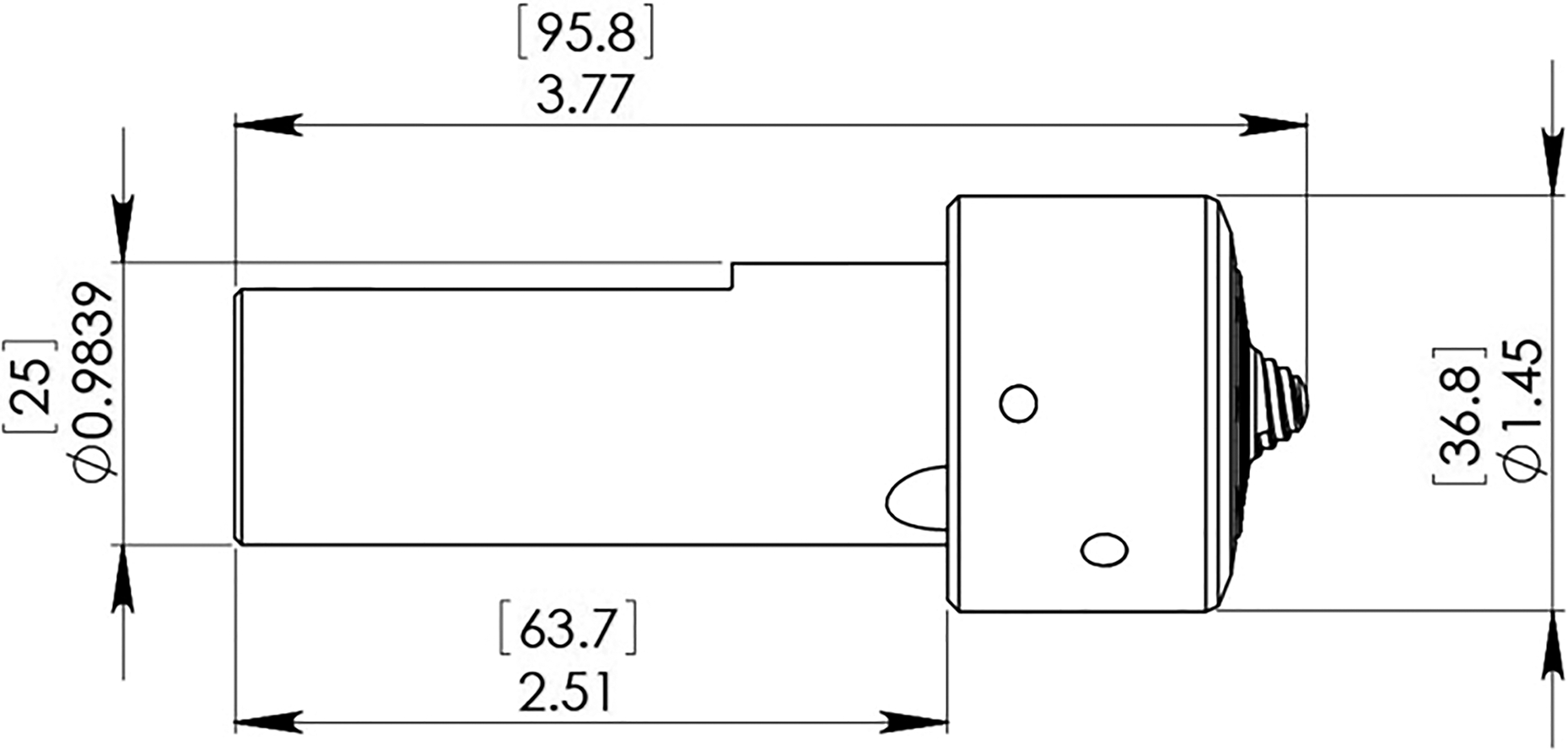
Geometry of FSW tool
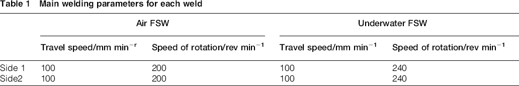
All welds were performed in the counter clockwise direction by embedding the tool to a reference level of 4.8 mm below the surface from both sides and a travel speed of 100 mm min− 1 and rotational speeds as shown in Table 1. The effect of this is to create a material flow vertically downwards in the weld towards the backing bar. This process is used to eliminate root defects in the weld. The friction stir mode used was position control in both cases. The higher rotation speed in the underwater weld was an attempt to compensate for the enhanced cooling effect underwater. On the basis of the parameters used, this would class the weld as a ‘slow’ weld. 18 In the case of the air welds, an argon gas shield was also used to prevent the welding zone and tool from oxidising. After welding, there was no evidence of tool wear or oxidation from the underwater weld.
Main welding parameters for each weld
Post-weld angular and longitudinal distortion was measured using an optical distance sensor control linked to a LabVIEW program that scanned the workpiece according to a predefined grid pattern. Each plate was secured on four locating points, which were calibrated using the optical distance sensor to result in zero deformation at these locations, spaced 380 × 800 mm apart. It was also assumed that the plates were initially flat before the welding process. Distortion measurements were recorded in 10 mm increments in both the longitudinal and transverse directions.
Transverse and longitudinal tensile tests, fabricated in accordance with BN EN ISO 4136:2011, were performed to assess the strength of the welded joints (three in each direction for both air and underwater FSW). The tensile specimens were 6 mm thick and 25 mm wide in the test zone.
Charpy impact toughness was determined using BS EN ISO 148-1:2010. As the specimens were subsize (5 mm), all the initial results were scaled up to a 10 × 10 mm equivalent using a factor of 1.5. The specimens (three for each location) were machined perpendicular to the weld centreline with notch positions − 6, − 4, − 2, 0, +2, +4 and +6 mm from the weld centre. The minus notation is the retreating side, and the plus notation is the advancing side.
Microhardness was measured in accordance with BS EN ISO 6507-1:2005 using a Mitutoyo MVK-G1 hardness tester. The load was 0.2 kg for 15 s.
Results and discussion
Distortion
The deformation profile for both the air and underwater FSW plates are shown in Fig. 2. A submerged arc welded (SAW) DH36 steel plate of the same dimension has been included to highlight the significant variation in distortion profile. All three plates show symmetrical distortion in the longitudinal direction. However, it is clear that the magnitude of distortion varies significantly between the FSW and the SAW plates. The underwater FSW plate exhibited the lowest distortion, with a deviation in the range of 5 to − 1.5 mm from the zero reference plane. The air FSW plate showed a slightly larger deviation in the range of 25 to − 5mm, while the SAW plate showed the largest deviation in the range of 110 to − 20 mm.
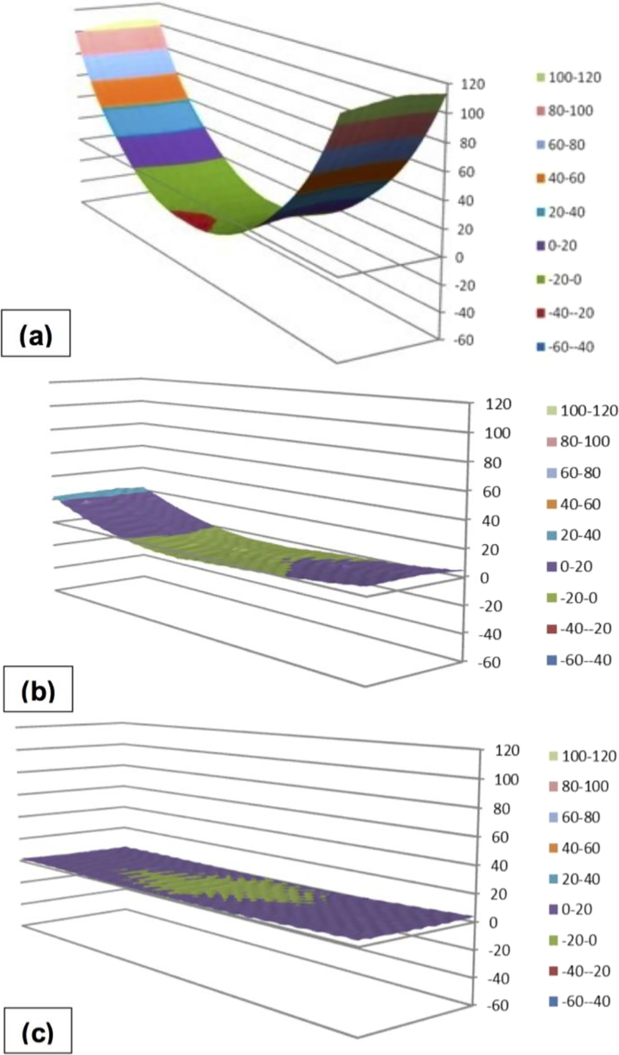
Distortion profiles for a submerged arc welded DH36 steel, b air FSW plate and c underwater FSW plate; Y-axis value indicates distortion from zero reference plane measured in mm
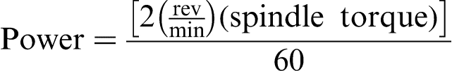
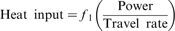
This can be explained by considering the difference in heat input between each of the welds. The heat input calculated by McPherson et al.
19
for the arc welded plate is 3.79 kJ mm− 1. The heat input for the FSW plates was calculated using equations (1) and (2), where f1 is the process efficiency
20
The large variation between the distortion in the SAW and FSW plates could be attributed to two factors. First, FSW plates are subjected to a higher degree of restraint during welding because of the clamping involved. This restraint mitigates against movement during welding and hence reduces distortion. The SAW process involves a phase change during welding as it goes from liquid to solid, whereas FSW is a solid state process. This means that the magnitude of the thermal stresses will be larger for the SAW plate due to the volume changes (longitudinal and transverse shrinkage) experienced during solidification and subsequent cooling to room temperature. However, there is also a phase change involved using this process.
Macrostructure
The macroetched images in Fig. 3 are the underwater and air welds respectively, and they show full penetration welds from both sides with an overlap region of ∼3.6 mm. The letters A and B represent the overlap region and TMAZ respectively. Table 2 describes the physical sizes of the two welds. Clearly, the underwater weld is larger. It is not surprising that the second side width of the underwater weld is larger due to the greater heat input used there. However, the first side weld width of the first side in the underwater weld is significantly wider (42%) than the air weld width. There could also be an issue related to tool condition, which would affect the weld geometry. These welds were not produced under conditions of exactly the same tool condition.
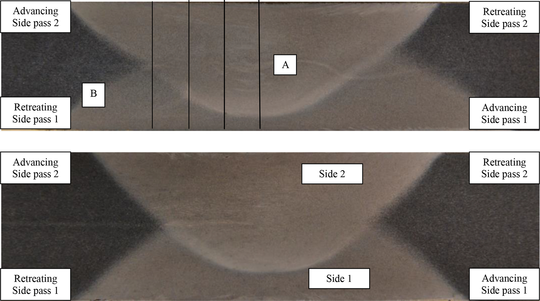
a underwater friction stir welded macrosection showing overlap region at A and area of TMAZ shown in Fig. 5a is at B and b air friction stir welded macrosection showing less second side penetration than in underwater sample shown in Fig. 5b
Dimensions of two welds
Microstructure
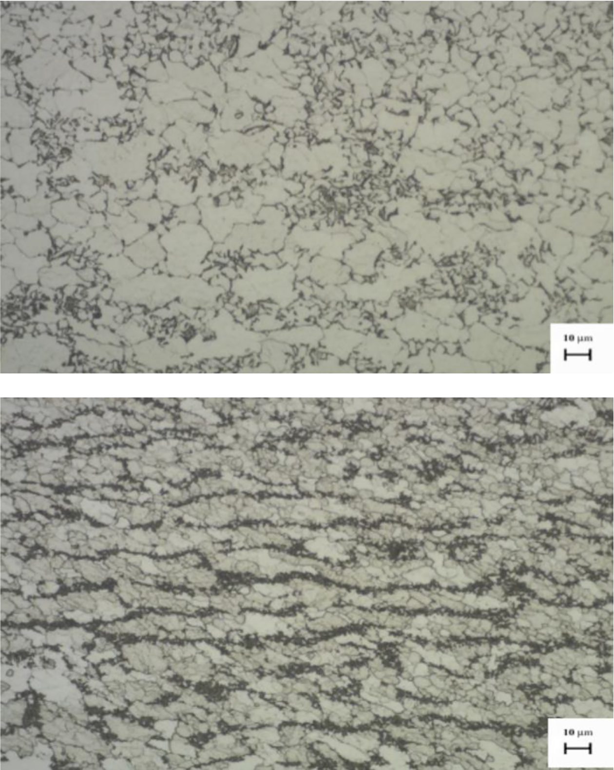
The microstructure of each zone was classified using an Olympus GX-51 microscope. The parent material shown in Fig. 4 has a microstructure of ferrite–pearlite with the effect of the lower carbon being obvious from the higher ferrite content. The parent plate had an average grain size of 13.5 μm. The structure shown is a cross-section at right angles to the major rolling direction, whereas in the case of the underwater weld, the microstructure was seen as being banded and had been taken parallel to the rolling direction. The remnants of this can be seen in Fig. 5b. Within the TMAZ (Fig. 5), it can be seen that the pearlite begins to degenerate in both cases, but to a greater extent, apparently, in the underwater treated sample. The average ferrite grain size is 11.4 μm, which is marginally smaller than the parent plate grain size. The ferrite grains within the air FSW plate (Fig. 5b) are smaller, but with a significant variation in size. The smaller recrystallised grains vary between 2.2 and 4 μm. However, there are a number of grains ∼12 μm, which is close to the parent plate size. In addition, the TMAZ was narrow in both samples and, as a result, did not significantly contribute to the strength or toughness of the weld. The overlap regions (Fig. 6), shows significant grain refinement as a result of severe plastic deformation and recrystallisation. The relative grain sizes are 3.8 and 3.1 μm for the underwater and air stirred welds respectively. These factors, as well as the elevated temperatures that the material experiences during FSW, resulted in the evolution of fine equiaxed grains. The overlap region consists of grains of ferrite with very fine particles of dispersed pearlite at the grain boundaries, but there appears to be slightly more pearlite in the air FSW samples compared to the underwater FSW material. However, in all other respects, the structures from the two samples were very similar. This is not dissimilar to the structure seen in the overlap regions of EH46 steel, where the grain size was measured at ∼2 μm. 21 This smaller grain size is from a niobium–vanadium microalloyed steel, whereas the carbon steel has no microalloys in it. In addition, the EH46 has a smaller overlap region and is significantly thicker (14.5 mm).
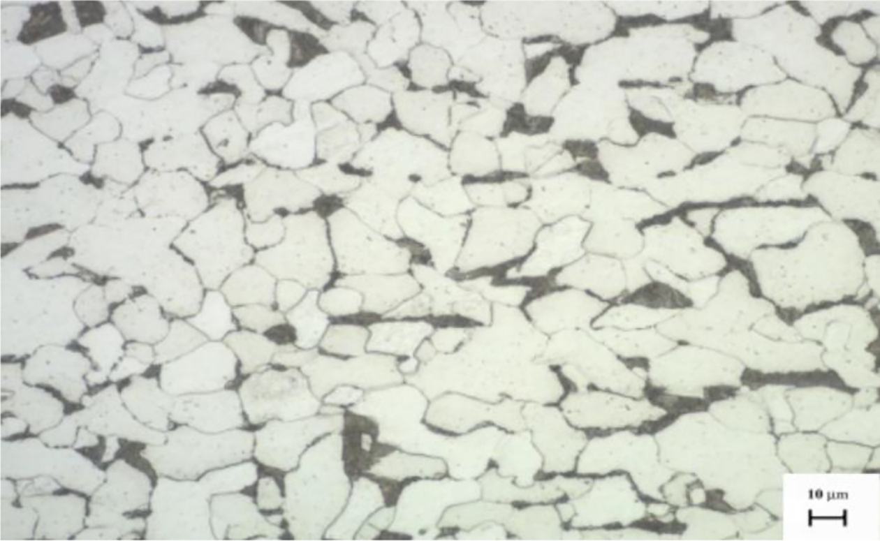
Parent plate material showing ferrite–pearlite structure taken at right angles to major rolling direction, for air FSW process
a thermomechanically affected zone showing pearlite degeneration in underwater FSW process and b TMAZ showing less pearlite degeneration and areas of ferrite recrystallisation in air FSW process

Compilation of microstructures in specific positions on each sample (underwater on left and air on right)

The microstructure in the middle of the surface showed some differences between the two processes. Typically, the air stirred microstructure was more angular, and the underwater structure was more predominantly a regular ferrite grain structure Subjectively, there was more angular ferrite in the air cooled welds than in the underwater weld. However, grain size measurements revealed strong similarities for each process. The centre of the weld in the first side was typically 4 μm, and the centre of the weld on the second side was 3 μm.
Overall, the structures of the two welds could be summarised as follows: the underwater weld contained predominantly regular ferrite in the overlap zone and side 2, and in side 1, there was more of a tendency towards an angular ferrite structure; the air welded samples had a less regular ferrite structure, with a consistent presence of angular ferrite, except in the overlap zone, which was regular ferrite.
One feature not identified to any significant extent in previous studies of friction stir welded material has been the presence of oxide deposits, which appear to have been stirred into the subsurface regions of the weld. This is shown in Fig. 7. In some instances, the depth of entrainment could reach almost the mid-thickness. However, this would have been accentuated by the tool design. As stated earlier, these plates had received no surface treatment after cutting, so there was oxide and paint primer in the stirring regions. Some of the areas were examined in the scanning electron microscope (SEM) with an EDAX attachment and found to contain no significant levels of silicon or zinc, which would normally be indicative of primer. However, in one sample area, shown in Fig. 8, only a level of 2.34% silicon was found, but the remainder was under 0.50%. It was concluded that it was predominantly surface oxide that had been drawn into the subsurface stirring zones. The remainder of the analysis in that particular point is 23.9% oxygen, 0.24% chromium, 0.84% manganese, 69.9% iron, 0.43% cobalt, 0.13% nickel and 2.17% copper.
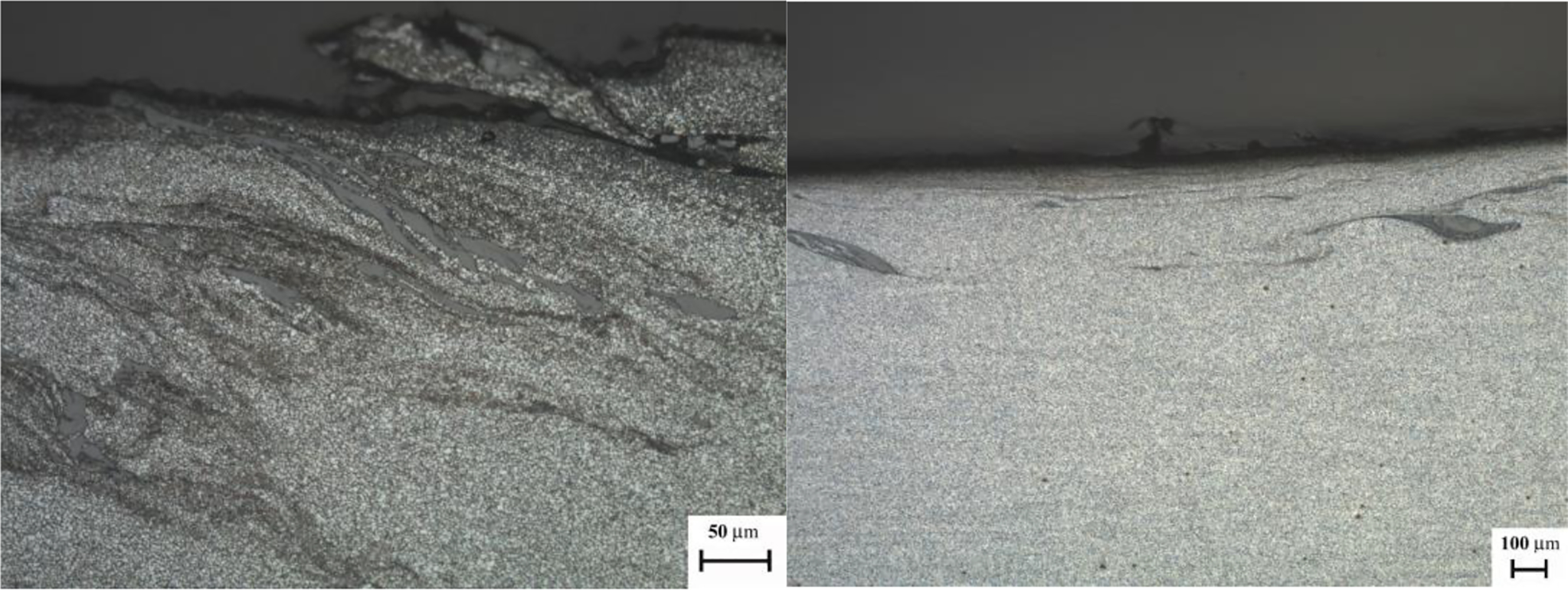
Areas of subsurface showing significant entrapment of scale from plate surfaces
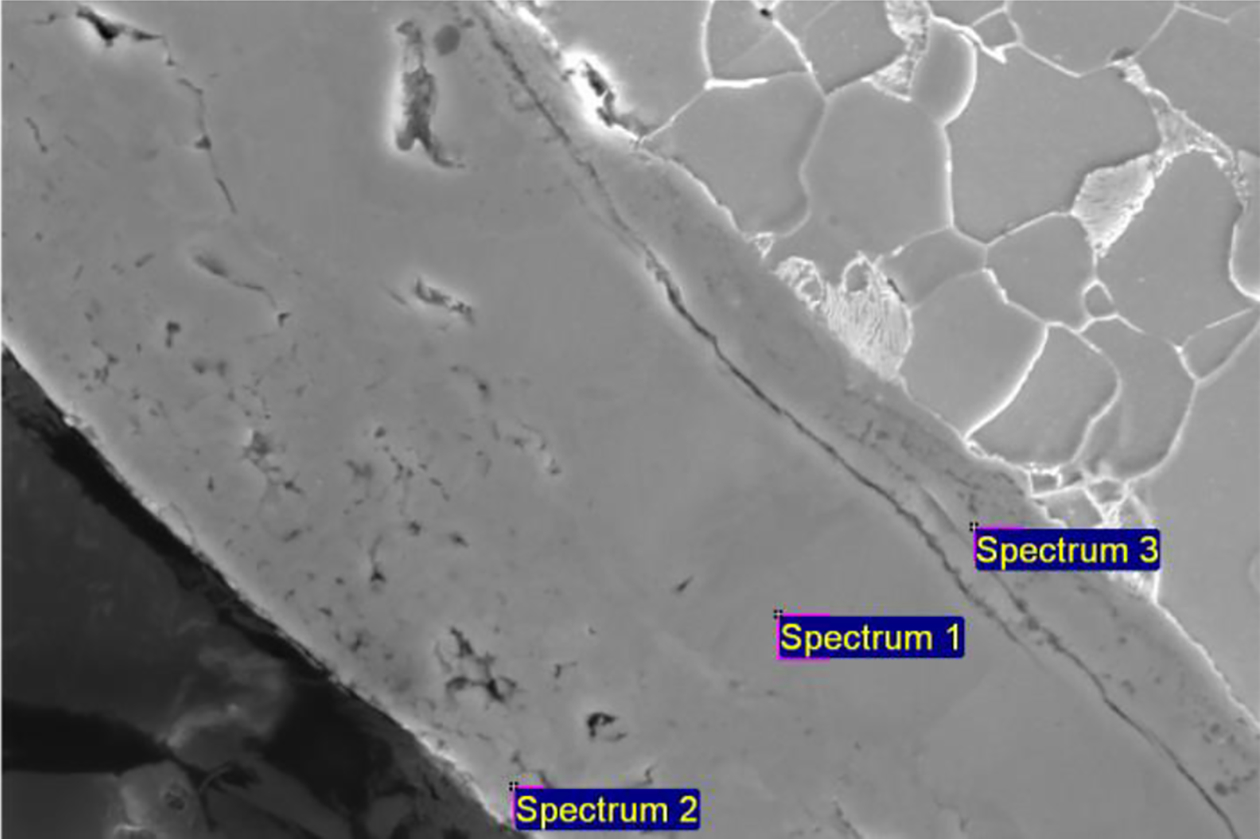
Image (SEM) showing oxide area beside steel; spectrum 3 region had 2.34% silicon from EDAX analysis
Mechanical properties
Tensile strength
In all cases, the transverse samples failed in the parent material, highlighting the superior strength of the weld metal. The longitudinal tensile tests produced results with considerably higher mean average yield strength and ultimate tensile strength (475 and 577 MPa respectively) than the transverse tensile tests that failed in the parent material (353 and 509 MPa respectively), equating to an improvement of 25.68 and 11.79% for the yield and ultimate tensile strength respectively. There was little difference between the longitudinal tensile strength of the underwater and air welded samples. This enhanced strength within the weld metal was attributed to the microstructure and grain refinement that occurred in the overlap region.
Microhardness
No significant variation in hardness between air and underwater FSW was observed. The microhardness did increase in the weld zone by ∼26%, but this does not reach a level that would cause any concern at all.
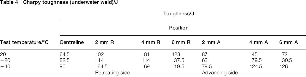
Charpy impact toughness
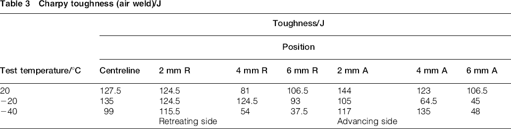
Figure 3a shows the relative position of some of the test positions. There can be a significant number of regions contained within one test area, possibly including some small proportion of parent plate. As a result of this, there is significant potential to have data with an inherent variability. Changes in the shape of the weld will also influence the toughness due to the relative notch position. The results of the toughness testing at 20, − 20 and − 40°C are shown in Tables 3and 4. It can be observed that the Charpy impact toughness is significantly reduced for the underwater FSW, attributed ostensibly from a faster cooling rate due to the water environment. However, when comparing advancing against retreating side toughness, there was no apparent consistency in the results. Other work 19 on DH36 steel has shown a similar inconsistency in toughness data. The explanation probably lies in the finer microstructural mix of the areas that are subjected to the impact test. The variability in toughness of friction stir welded carbon steels may actually be a characteristic of the process, and as data 18 build up, then a clearer situation will develop. The variation in the microstructure, although on a relatively fine scale in this work, could also be indicative of the potential source of the variation in toughness being observed. The work of Guillaume et al. 22 showed wide variations in toughness values in the same area and from area to area in 8 mm thick DH36 friction stir weld. At − 20°C, the toughness was lower than that recorded here. However, the microstructure was significantly different to that observed in this work, too. In that case, it was almost a Widmanstätten structure that was present, which would partially explain the toughness of the weld.
Charpy toughness (air weld)/J
Charpy toughness (underwater weld)/J
Fatigue
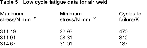
Low cycle fatigue testing was performed at a stress level of 90% of the measured yield strength. The mean average cycles to failure for the air and underwater specimens were 301 and 745 K cycles respectively. Although the ratio of these two mean values may be considerable in absolute terms, there is almost no difference between the longest and shortest lives within each set of results as shown in Tables 5and 6.
Low cycle fatigue data for air weld
Low cycle fatigue data for underwater weld
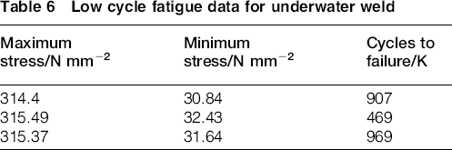
To assess the significance of the results, a statistical analysis was performed. 23 The test showed that, if the two populations had identical properties, there would be a 6.4% probability of obtaining an apparent difference greater than that seen in the experiments. This is marginally higher than the benchmark figure of 5% that would be required before making any claim that the results were significantly different. Comparing the log normal distributions shown in Fig. 9a, it can be seen that there is no significant difference in the fatigue performance of the air and underwater welds. This is further confirmed by considering the pooled data in Fig. 9b. If there were two distinct populations (i.e. fatigue life), the graph in Fig. 9b would show some variation from linearity.
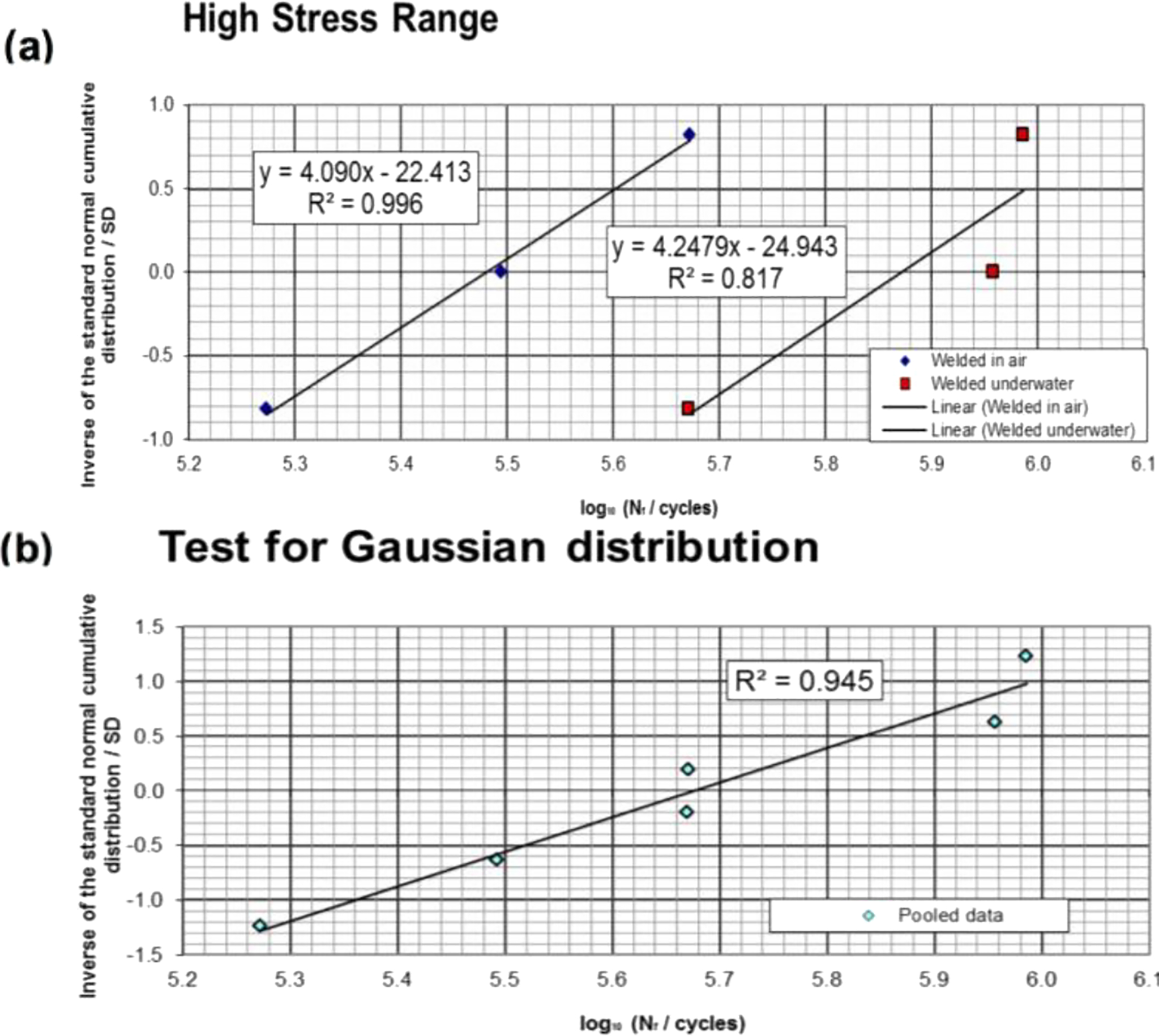
a log normal distribution and b pooled data, for air and underwater FSW specimens
Conclusions
This study has shown that FSW can be successfully completed underwater for S275 structural steel without any adverse effects to the strength, hardness or fatigue life of the material. Charpy impact toughness was, however, shown to decrease for the underwater weld. Within the available data, it is difficult to fully explain the toughness difference as the relative grain sizes do not vary significantly. The potential difference may lie in fine scale differences in the microstructures.
Between the processes, the longitudinal tensile results are the same, and the microhardness does not vary. It was also shown that underwater FSW has benefits compared to SAW and FSW in air. This was apparent in the distortion results where it was shown that FSW underwater significantly reduces angular and longitudinal distortion in the workpiece.
Lack of surface preparation can lead to the presence of stirred in oxide particles, which can have a localised effect on the grain structure within the welds. This conclusion is made for both FSW conditions in this study.
Acknowledgements
The authors wish to acknowledge the support of TWI and Tata Steel Europe in this study.