
Abstract
Additive and non-additive T joints were successfully fabricated by stationary shoulder friction stir welding using various welding parameters. No interior defects were observed in all joints by microstructural examination. The fatigue property of both additive and non-additive joints was revealed by four-point bending fatigue test. The microstructure and the stress concentration were investigated at the fatigue crack initiation sites of various T joints. Stress concentration determines the fracture location, and the surface microstructure influences the fatigue property. The stress concentration at the internal corner was evidently lower for additive joint than non-additive joint. The surface of stationary shoulder friction welded joint was characterised by ultrafine grains, which evidently enhanced the fatigue property.
Keywords
Introduction
Stiffener reinforced structures, which are called corner joints or T joints in welded structures, are widely used in aerospace and transportation industries.1, 2 In the past, T joints were mainly manufactured by arc welding, leading to severe strength degradation, large residual stress and distortion. 3 The invention of conventional friction stir welding (CFSW) provides potential solid state welding solution for the manufacturing of high quality and robust T joints. Up to now, the microstructure and mechanical properties of CFSW T joints have been reported in the open literature.1, 4–6 However, full penetration and defect free T joint can be hardly obtained due to the rotational shoulder utilised in CFSW.
Stationary shoulder friction stir welding (SSFSW), which is a novel variant of CFSW, employs a stationary shoulder component and provides the accessibility to the welding of defect free T joints by double pass welding at the internal corners of T joint.7–11 The feasibility of the manufacturing of defect free additive and non-additive T joints by SSFSW has been proven by The Welding Institute (TWI).12, 13 Tensile tests showed that both additive and non-additive stationary shoulder friction stir welded T joints exhibited satisfied joint coefficient.9, 11, 13 Nevertheless, such structures usually suffer from alternative loads and fail at low stress level due to fatigue. Up to now, the fatigue property of stationary shoulder friction stir welded T joints has not been studied in the open literature. In this paper, both additive and non-additive T joints were made by SSFSW. The fatigue property of the joints were investigated by four-point (4P) bending fatigue tests. In addition, the influencing factors on the fatigue property were analysed in detail.
Experimental
Welding tools and process
The base material (BM) used was 5 mm thick sheets of AA6061-T4. The filler rod for additive T joints was commercial 5356 aluminium welding rod with 3.2 mm diameter. Both additive and non-additive T joints were produced by self-made tool packages. The welding process and tool package for the additive T joints are shown in Fig. 1. The springs and pressing unit were removed in the fabrication of non-additive T joints. The shoulder for non-additive and additive T joints are illustrated in Fig. 2.
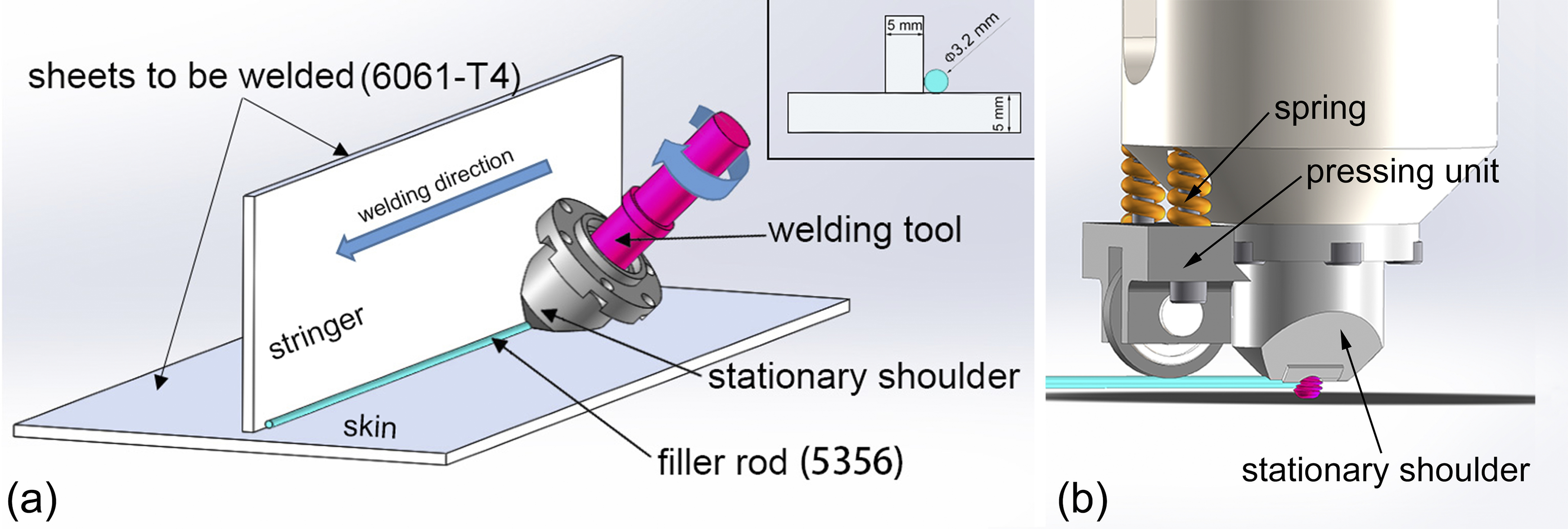
a welding process and b tool package for additive T joint
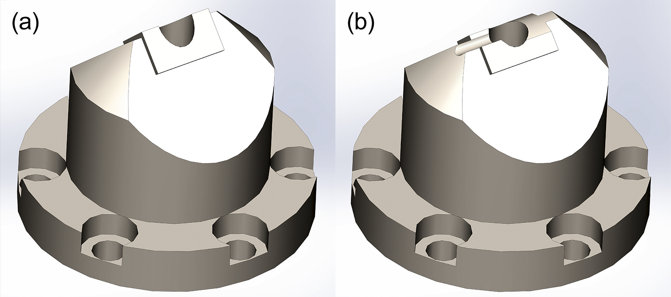
a for non-additive joint; b for additive joint
The welding parameters for non-additive and additive joints were 1500 rev min− 1 and 100/300 mm min− 1 and 1500 rev min− 1 and 100 mm min− 1 respectively. The welding process was carried out in the direction perpendicular to the rolling direction of the sheets to be welded.
Microstructure examination
Microstructural examinations were made on the transverse section of the metallographic specimens prepared by grinding, polishing and etching using the optical microscope Olympus GX 51.
Fatigue test
Fatigue specimens with 10 mm width and 100 mm length were cut from various welds by electric spark cutting machine. No subsequent surface treatment was performed, and the specimens were directly used in 4P bending fatigue tests under as welded condition.
Four-point bending fatigue tests were performed to reveal the fatigue performance of additive and non-additive T joints by Instron ElectroPuls E 10000 fatigue testing machine using load control mode in lab air. A sine wave load with the stress ratio of 0.1 was applied under the loading frequency of 30 Hz for all tests. The testing set-up is shown in Fig. 3. Four-point bending fatigue test creates uniformly distributed nominal principle stress on the tensile surface (see Fig. 3b). Thus, fracture would occur at the point where the lowest fatigue property locates. Four-point bending fatigue tests were conducted for both types of T joints under all welding parameters at six nominal stress ranges between 121 and 171 MPa. For each stress range, three duplicate specimens were tested. The set-up of 4P bending fatigue test is shown in Fig. 3a.
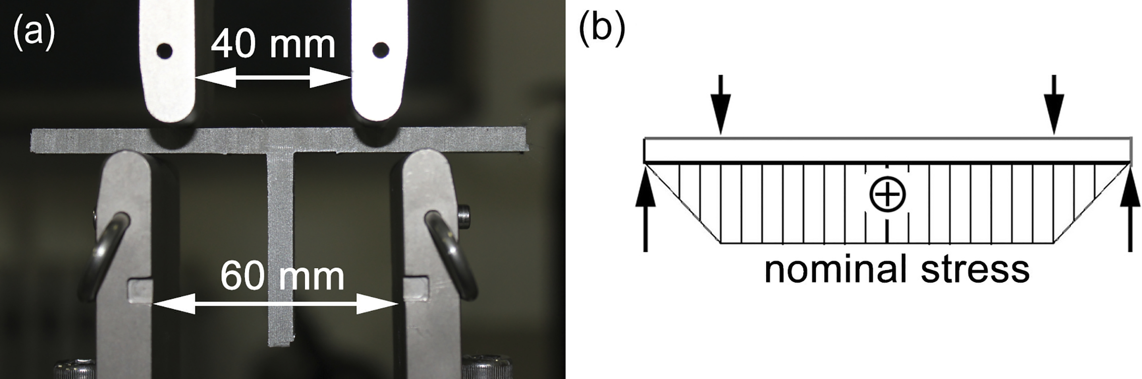
a test set-up and b nominal stress distribution
Mean S–N curve was plotted in a log–log coordinate using nominal stress range according to the statistical analysis method addressed in standard IIW-XIII-WG-114-03. The fatigue tests were terminated when the fatigue life exceeded 2 × 10⁶ cycles, at which the stress range is usually considered to be the fatigue limit for welded joints.
Determination of stress concentration coefficient
Individual solid models were built according to the macrograph of additive and non-additive joints made at different welding parameters. The principle stress distributions in 4P bending test were analysed by finite element analysis software Abaqus at a given load of 1012 N. The stress concentration coefficients on the given paths were calculated.
Results and discussion
Macrograph of transverse section
The transverse section macrographs of additive and non-additive T joints by SSFSW are shown in Fig. 4. No interior defects can be observed in both types of T joints. However, the plunge depth of the additive joint is evident compared with that of non-additive joint. In additive T joint, the filler material was successfully added to the joint with different mixing extents with the BM at various positions. The poorly mixed position is enlarged in Fig. 4c. Although the filler material and the BM show a limited mixing extent, the bonding of filler material and the BM is compact and defect free. The plunge depth of non-additive T joint is very small. The grains in the nugget zone shows different recrystallisation degree due to the complex material flow condition.
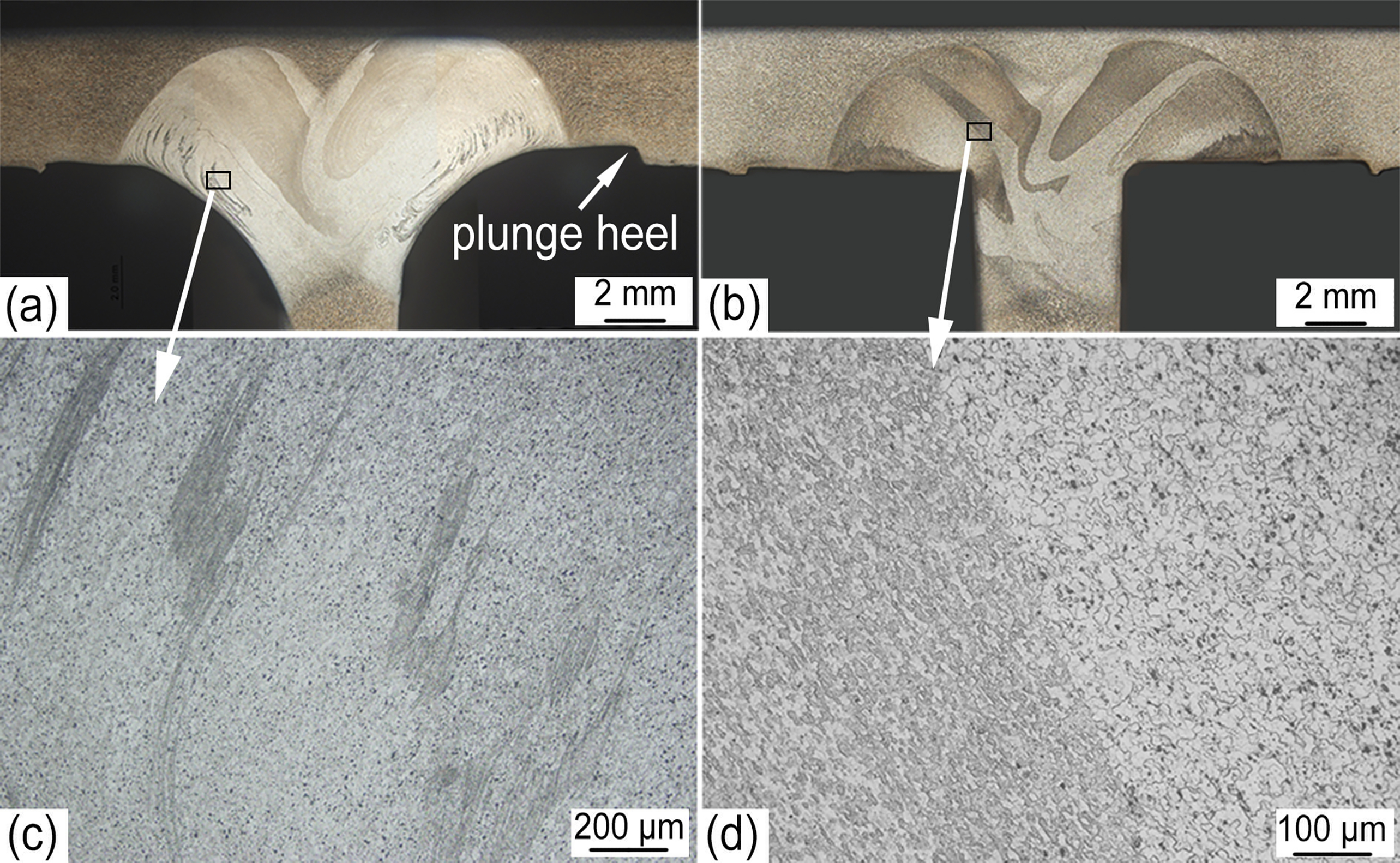
a additive joint; b non-additive joint; c, d enlargement of marked positions in a and b respectively
Fatigue property
The fatigue crack initiated at the sharp internal corner of non-additive T joints (see Fig. 5a). For non-additive T joint, the stationary shoulder employed a right angle contour in order to match the internal corner of T joint and to constraint the softened material. Meanwhile, the shoulder behaves as a mould for the weld formation, leading to a sharp internal corner. The sharp transition of cross-section area results in severe stress concentration in the cyclic loading, consequently leading to the fatigue crack initiation.
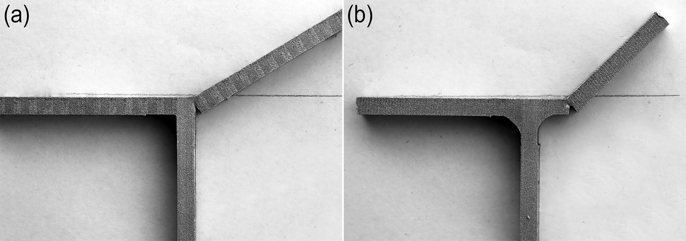
a non-additive joint; b additive T joint
While for additive joint, the filler material was added in the welding process and formed fine fillet radii at the internal corner of the joint. The smooth transition of cross-section area at the internal corner greatly reduced the extent of stress concentration. However, the plunge heel in additive T joint created new structural discontinuity. Thus, the fatigue fracture occurred at the plunge heel of the additive T joints.
The results in 4P bending fatigue tests and various S–N curves for additive T joint at 1500 rev min− 1 and 100 mm min− 1 and non-additive T joint at 1500 rev min− 1 and 100/300 mm min− 1 are shown in Fig. 6. The fatigue performance of additive T joint is evidently better than that of non-additive T joint at different welding parameters. While for non-additive T joints at different welding speeds, the T joint made at low welding speed (100 mm min− 1) showed better fatigue performance than that at high welding speed (300 mm min− 1). Besides, the fatigue life of all three additive joints exceeded 2 × 10⁶ cycles at the nominal stress level of 135 MPa, which is much higher than that of the non-additive T joints under various welding speeds.
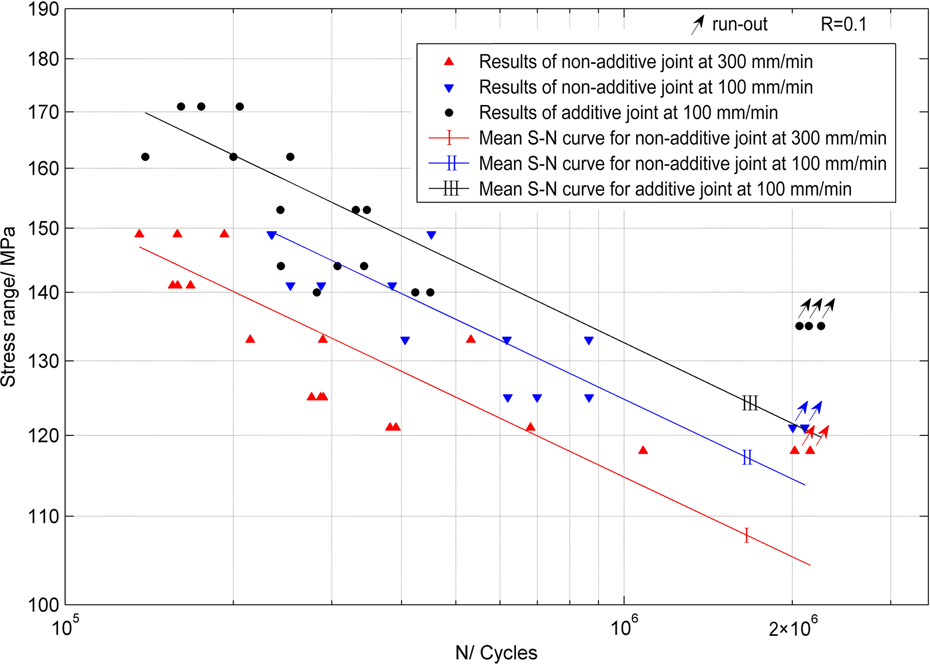
S–N curves for additive and non-additive T joints by SSFSW
Principle stress distribution
In 4P bending fatigue test, the tensile surface of the joint endures the largest principle stress. Thus, fatigue crack always initiates at the tensile surface of defect free joints. Besides, the majority of the fatigue life of welded joints is related to the fatigue crack initiation stage. Thus, the principle stress distribution on the tensile surface is the key factor influencing the fatigue performance of T joints.
The principle stress distributions on given paths on the tensile surface of various types of T joints are shown in Fig. 7. Large stress concentration can be observed at the internal corner of non-additive T joints. While for additive T joint, the stress concentration at the internal corner is greatly reduced. However, the plunge heel in additive T joint introduced fairly large stress concentration. The results of fatigue test showed that all T joints fractured at the position where the largest stress concentration located.
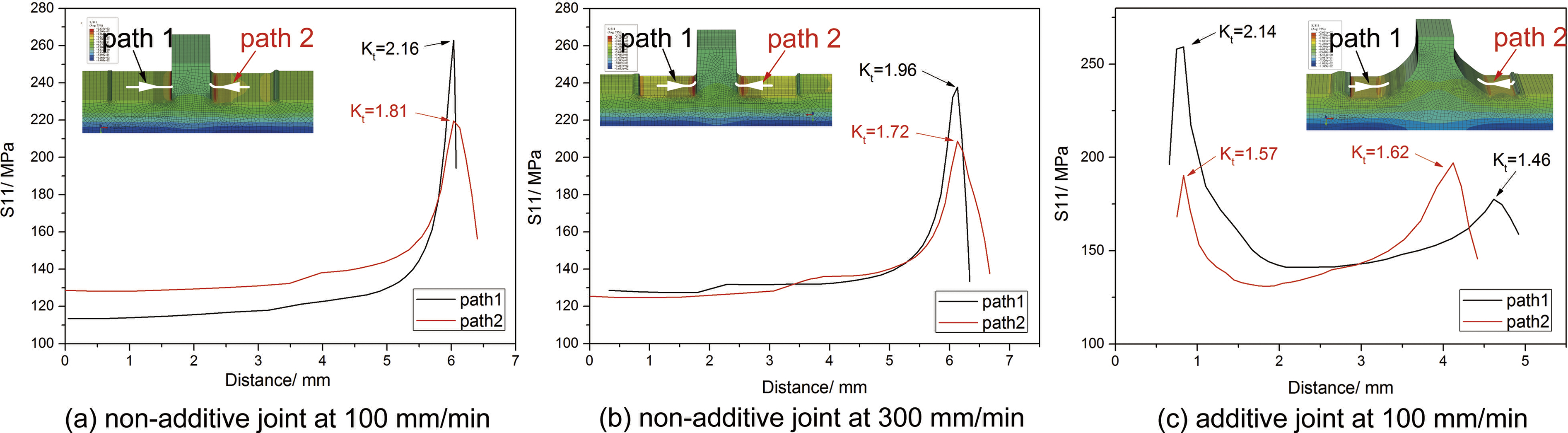
Principle stress distributions on given paths of various T joints by SSFSW
The largest stress concentration coefficient in non-additive T joints made at 100 mm min− 1 is 2.16, which is higher than that made at 300 mm min− 1 (i.e. 1.96). However, it can be seen in Fig. 6 that the fatigue performance of non-additive joint made at 100 mm min− 1 is evidently better than that made at 300 mm min− 1. Meanwhile, the fatigue performance of additive T joint is much better than that of non-additive T joint at 100 mm min− 1 with similar stress concentration coefficients (2.14 for additive joint and 2.16 for non-additive joint).
Thus, the fatigue crack initiated at the position with the largest stress concentration coefficient for all T joints. However, the fatigue performance was not determined by the stress concentration.
Microstructure at crack initiation site
The microstructures at the fatigue crack initiation sites for all T joints were examined. The surfaces at the internal corner of non-additive T joints at different welding speeds were both characterised by ultrafine grains, as shown in Fig. 8a–d. The grain size at the crack initiation site was finer in T joint at 100 mm min− 1 than in T joint at 300 mm min− 1. During the welding process, much more deformation occurred and led to finer grains in the nugget zone of non-additive T joint at low welding speed. Microhardness was similar on the surface layer at the internal corner of non-additive joints at different welding speeds.
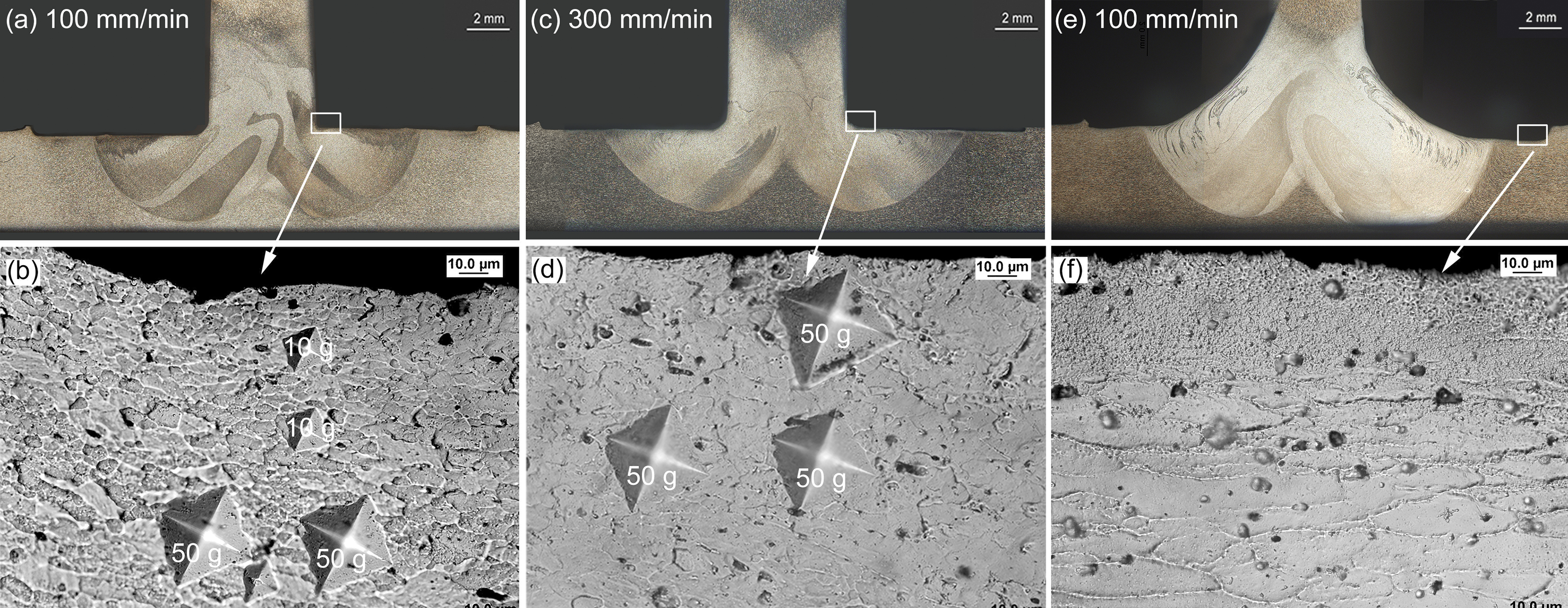
Microstructure at various locations of non-additive and additive T joints by SSFSW
Figure 8e and f shows the surface microstructures at the plunge heel of additive T joint. Partial recrystallisation occurred on the surface layer due to the effects of the welding heat and the deformation caused by the stationary shoulder. However, the surface cooled down quickly before the grains grew up to a larger size. As a result, the grain size in the surface layer is too fine to be identified even under the highest magnification by optical microscopy (see Fig. 8f ).
It can be found that finer grain size at fatigue crack initiation site leads to better fatigue performance regardless of the type of T joints.
It is well known that fatigue crack initiation occurs at low stress amplitudes, at which plastic deformation is limited to a small number of grains in the favourable slip planes on the material surface. In these grains, a large shear stress will be needed for further slip in the same slip band due to strain hardening.14, 15 In the case of ultrafine grains, there are many grains with various slip planes. When strain hardening occurs in certain grains, the slip planes in other grains may be activated, leading to more uniform deformation and less strain concentration, which could evidently enhance the fatigue performance. Therefore, finer grains at the crack initiation sites would lead to enhanced fatigue performance for both types of T joints.
Conclusions
Additive and non-additive T joints were successfully made by stationary shoulder friction stir welding using different welding speeds. The fatigue properties were tested by 4P bending fatigue experiments. The influences of stress concentration and grain structures at fatigue crack initiation sites on the fatigue property were revealed. The main conclusions are listed below.
Defect free additive and non-additive T joints can be fabricated by stationary shoulder friction stir welding. The fillet radii greatly reduced the stress concentration coefficient at the internal corner in additive T joints. However, the plunge heel introduced severe stress concentration in additive T joints. Additive T joints showed better fatigue property than non-additive T joints at various welding speeds. Meanwhile, the fatigue property of non-additive T joints at 1500 rev min− 1 and 100 mm min− 1 was evidently better than that at 1500 rev min− 1 and 300 mm min− 1. The location of fatigue fracture was mainly determined by the stress concentration. The ultrafine grains at fatigue crack initiation site evidently enhanced the fatigue property of stationary shoulder friction stir welded T joints regardless of the joint configuration.