
Abstract
The keyhole wall is the interaction interface between the laser and the material during the laser deep penetration welding. Measuring the morphology of the keyhole wall is thus of significance for understanding the high power fibre laser deep penetration welding process. In this paper, the clear keyhole wall was reserved by suddenly closing laser during high power fibre laser welding of copper alloy. The results indicate that the keyhole can be divided into laser action region and metallic vapour pressure maintenance region. The laser action region is on the front wall of keyhole, and a series of concentric elliptical rings are observed in this region. In another region, its diameter is significantly larger than the spot diameter and the keyhole wall is basically smooth. The results are different from those generally accepted viewpoints, which clarify the flowing law of molten fluid in the keyhole and are thus of great guiding significance for optimising the welding technology.
Introduction
The laser welding technology has been widely applied in a variety of industries owing to its several advantages such as a large depth/width ratio of the welded joints, small heat affected zones and high flexibility superior to traditional welding techniques.1, 2 Recently, due to its advantages such as high beam quality, high flexibility and low operating costs, the high power fibre laser has been expected as one of most desirable heat sources in laser welding field.3, 4 Nevertheless, thorough understanding on high power fibre laser deep penetration welding process is still scarce so far (e.g. excessive spatters in welding and poor shapes of welding joins 3 ), and thus, the development has been severely restricted. Generally, the keyhole wall is the interaction interface between laser and materials during laser deep penetration welding. Obtaining the clear morphology of the keyhole wall will be of great guiding significance for understanding the high power fibre laser deep penetration welding process.
In theory, the main viewpoint of keyhole wall is that significant fluctuations exist in the keyhole front wall due to the instability of runaway in laser deep penetration welding. 5 The front wall surface of keyhole, described using the theory, is similar to a series of steps ascends along the keyhole5–10 and is still not confirmed in experiment. In the experiment, the keyholes may be observed adequately from the lateral side using X-ray photography 3 or the sandwich structure consists of glass and metal. 11 Unfortunately, the clear keyhole wall morphology could hardly have been acquired using these two methods due to too small keyhole. The keyhole front wall can be observed using high speed camera with overhead observation above the weld plates.12–14 However, the reflected light of the illumination light on the keyhole front wall cannot always been caught by the high speed camera. In addition, the evaporation airflows above the front wall of keyhole can cause serious disturbances. The images obtained from the keyhole front wall are thus always blurry, resulting in great losses of important information on the keyhole front wall. Therefore, a novel and reliable method needs to be used for observing the keyhole wall during high power fibre laser deep penetration welding.
In this study, the bead on plate welding was carried using a high power fibre laser on the copper–zirconium–hafnium alloy (Cu–Zr–Hf). The keyhole was reserved due to the rapid cooling of Cu–Zr–Hf with high thermal conductivity. Then, the morphology of the keyhole wall was measured by a scanning electron microscope (SEM) and optical microscope. In addition, the results were analysed and discussed.
Experimental
The schematic diagram of the experiment set-up is presented in Fig. 1. The CW high power fibre laser (YLS-6000, IPG Photonics, USA) has 1070 nm in wavelength. The laser beam was delivered through an optical fibre of 200 μm in core diameter, collimated with the Collimator Lens of 200 mm focal distance and focused into 0.3 mm in spot diameter and 3.05 mm in Rayleigh length by the lens of 300 mm focal distance. The laser head was displaced using a robot hand manufactured by Kuka Company during the welding process.
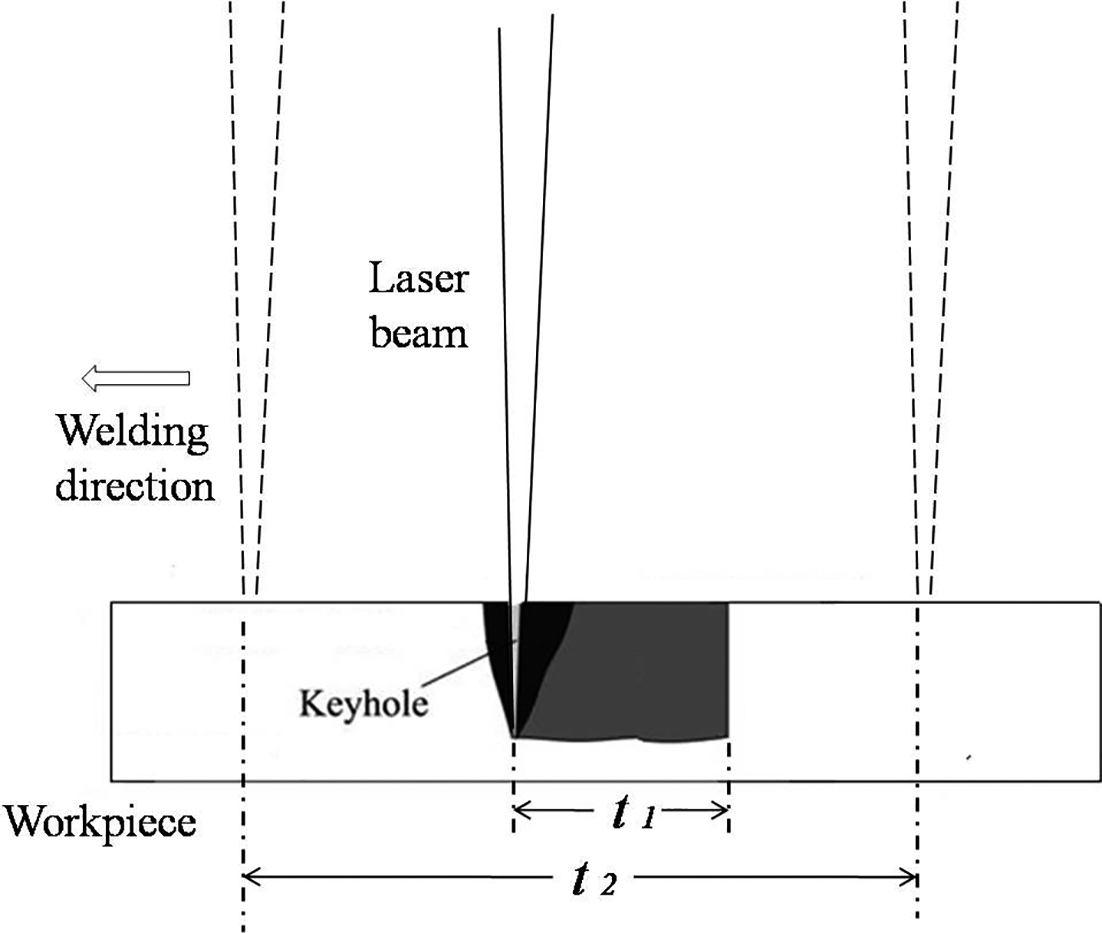
Schematic diagram of experiment set-up
The bead on plate welding was carried using a fibre laser with 0 mm in defocus distance on the Cu–Zr–Hf with the size of 200 × 50 × 10 mm3. The chemical composition of Cu–Zr–Hf used is Cu–0.33Zr–0.65Cr–2.41C–5.93Hf, wt-%. The laser was suddenly turned off during the scanning process. The keyhole wall morphology was thus reserved due to the rapid cooling of Cu–Zr–Hf with high thermal conductivity. The total scanning time of laser (i.e. t2 in Fig. 1) was 2 s, and the output power time of the laser (i.e. t1 in Fig. 1) was 0.2 s. The output power of the laser was 5 kW in 0.2 s (i.e. t1 in Fig. 1) and 0 kW in rest time. In order to prevent the high reflectance of the Cu–Zr–Hf damaging the fibre laser, the incidence angle of laser beam was set to be 5° on Cu–Zr–Hf. The molten pool was protected using the nozzle with an argon flow of 15 L min− 1. The shielding gas flow direction was along the welding direction and parallel to the surface of weld plate. The keyhole wall morphology was measured using an SEM (FM 300, Hitachi, Japan) and an Olympus optical microscope.
Results and discussion
The overhead view of the keyhole at different welding speeds were observed using an SEM, as shown in Fig. 2. When the welding speed was 0 m min− 1, it was the laser drilling. As shown in Fig. 2a, the keyhole mouth is circle with a diameter of 0.8 mm, and there is a series of concentric rings along the keyhole wall. When the welding speed was changed to 2 and 4 m min− 1, as presented in Fig. 2b and c, the keyhole mouths were no longer circle but exhibited two circular ringed regions, which have different diameters and are interlaced with each other, namely, region A and region B. Region A with both the vertical (along the welding direction) and horizontal lengths of 0.4 mm presents a series of regular ripples in the keyhole wall, while region B has smooth surface of the keyhole wall, with vertical lengths of 1.105 and 1.577 mm and horizontal length of 0.8 mm respectively.
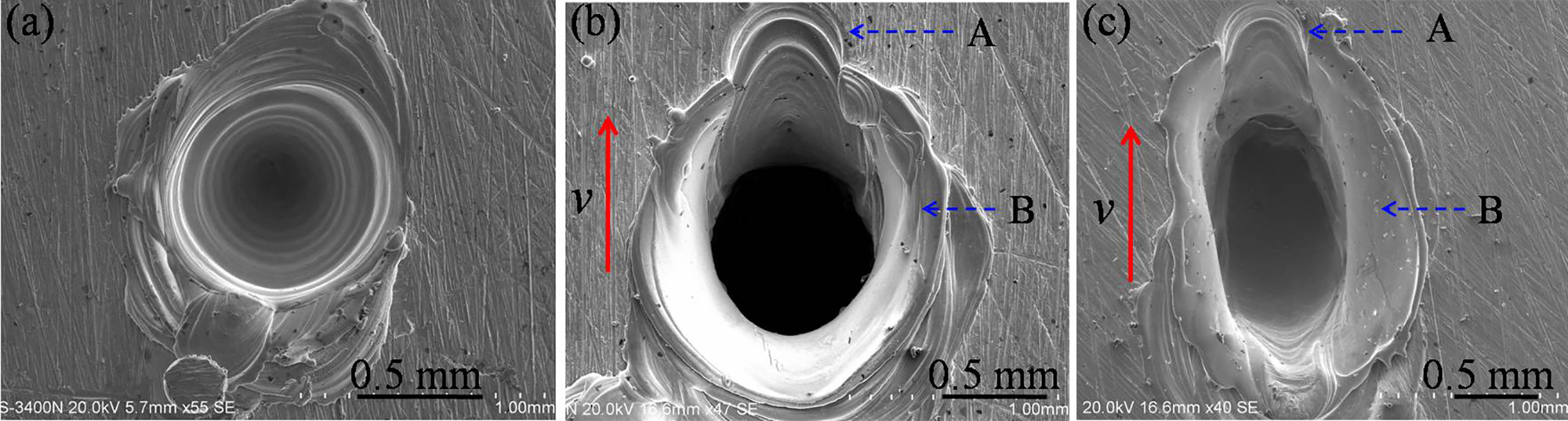
Keyhole at different welding speeds: a 0 m min− 1; b 2 m min− 1; c 4 m min− 1
The main composition of Cu–Zr–Hf is copper. Thus, its thermal properties should be similar to that of the copper and very high. In addition, according to Fig. 2, it can be found that the rings in keyhole wall are very regular. This indicates that the keyhole wall should be quickly frozen as the laser energy is shut off. The morphology of keyhole wall is thus reserved.
During the laser drilling, the molten liquid was ejected from the keyhole due to the effect of the evaporation recoil pressure. This process is similar to a piston effect.15, 16 The radial energy distribution of the laser spot, adopted in this study, could be approximately regarded as Gaussian. Accordingly, in the laser induced evaporation recoil pressure, a Gaussian distribution along the radial direction of spot followed. During the drilling process, the absorption of the laser by the keyhole wall varied with the increases of the keyhole depth (i.e. the incidence angle varied), leading to the variation of evaporation recoil pressure. Owing to the variational piston effect, the rest of molten fluid was retained on the keyhole wall, and then a series of concentric rings were formed. During the laser welding, the above described region A is the laser action region, whose diameter is approximately equal to the spot diameter and the surface of region A is the keyhole front wall. Inside the keyhole, the vapor pressure was quite high during laser deep penetration welding. To maintain the pressure balance in the keyhole, the diameter of region B increased significantly on account of the vapour expansion, i.e. region B can be viewed as the metalic vapour pressure maintenance region. When the metallic vapour was ejected from the keyhole, the friction between metal vapour and keyhole wall produced a comparatively smooth keyhole wall in region B.
The keyhole was dissected along the direction, which is perpendicular to the welding direction, while the clear morphology of the keyhole front wall is displayed in Fig. 3. Several regular ripples, i.e. a series of concentric elliptical rings, can be observed on the front wall. As shown in Fig. 3, A denotes the keyhole mouth of the laser action region, B denotes the rest of metalic vapour pressure maintenance region after being cut off with a smooth wall, C denotes the depression at the centre of eplliptical rings, D denotes the smooth ripple, and E denotes the relatively coarse ripple below the front wall. The picture of keyhole front wall in this study is apparently different from the generally accepted viewopionts.5–13 The laser induced evaporation recoil pressure on the keyhole front wall can be approximately regarded as a Gaussian distribution, which is also similar to the Gaussian piston effect during the process of laser drilling. At the centre of the circle, the recoil pressure was maximum, giving rise to a depression. Under the action of the recoil pressure gradient, the molten fluid on the front wall would flow along the interface, with the adoption of the centre of recoil pressure as the centre of circle. On account of the relative movement between the laser beam and the keyhole front wall as well as the constraint of side wall of keyhole on the molten fluid flowing on the front wall, the ripples on the keyhole wall were elliptical rather than circularly concentric during the laser drilling as shown in Fig. 2a. In addition, the keyhole front wall morphology at two different welding speeds are almost identical.
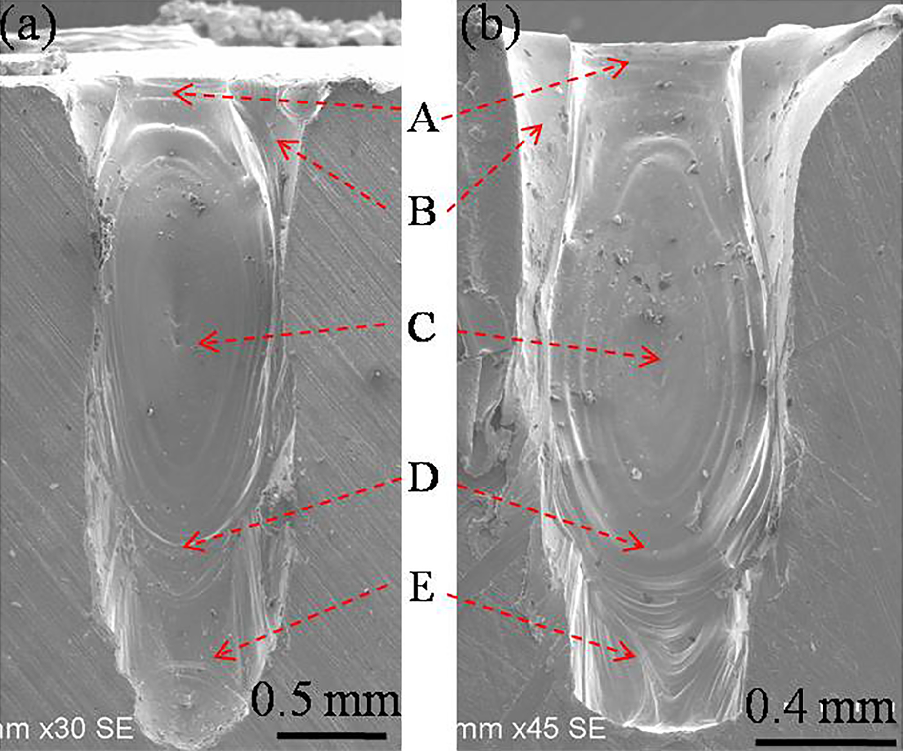
Micromorphology of keyhole front wall: a 2 m min− 1; b 4 m min− 1
The experimental sample as shown in Fig. 3a was cut along the welding direction, and then the side of the front wall was corroded by concentrated nitric acid. Using Olympus optical microscope, the keyhole side wall morphology was observed and displayed in Fig. 4a, in which F denotes the extension parts of the concentric elliptical rings from the front wall to the side wall. A denotes the side wall of the laser action region at the mouth of keyhole, and B is the vapour pressure maintenance region with a smooth surface. It is found that the melting thickness of the front wall of keyhole is inconsistent. Its bottom is ∼0.09 mm, and the middle and top are ∼0.458 mm.
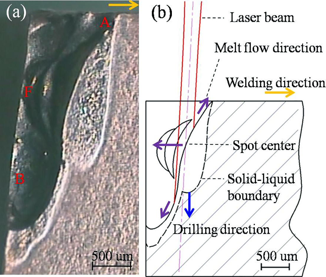
Side wall morphology of keyhole (v = 2 m min− 1)
The distance between the centre of the concentric elliptical rings as shown in Fig. 3a and the plate surface was measured to be 1.02 mm. With the circle centre as the laser spot centre, the schematic picture of the laser beam action on the keyhole front wall was constructed and presented in Fig. 4b, in which the actual sizes of the Gaussian beams and keyhole were used. It can be observed that the laser beam directly acted on the keyhole front wall during deep penetration welding. Moreover, the molten thickness in the laser action region was comparatively large. The distance between the circle on the side wall (i.e. F) in Fig. 4a and the front wall was ∼0.68 mm, from which we can conclude that the molten fluid at the centre of circle on the front wall had flowed for some time. This result suggests that the action position of laser beam, which was obtained based on the circle centre on the front wall in Fig. 4a, is actually not located at the same position at the same moment that the laser was suddenly shut off. During welding, the laser beam moved from the keyhole bottom to the front wall edge. When the laser was suddenly shut off, the leading edge of the laser was coincident with that of the front wall mouth. Since the thermal conductivitiy of Cu–Zr–Hf is great, the morphology when the laser moved from the keyhole bottom to the leading edge of front wall was retained in the keyhole wall.
According to these elliptical rings on the keyhole front wall, it can be ensured that the keyhole front wall is the source of molten fluid flowing in the keyhole during high power fibre laser deep penetration welding. The molten liquid on the keyhole front wall not only flows toward the bottom of the keyhole but also moves toward the side wall and the top of front wall, as marked by the purple arrows in Fig. 4b. In the upper section of the keyhole front wall, the amount of molten liquid increased significantly. This indicates that a significant portion of the laser energy was absorbed. Under the action of this intense evaporation recoil pressure (it should be noted that its direction is downward and perpendicular to the front wall surface), a large proportion of molten metal fluid on the front wall would flow downward toward the keyhole bottom. The phenomena indicate that the formation of the keyhole was similar to the laser drilling on the keyhole front wall during welding, and the drilling direction is marked by blue arrow in Fig. 4b.
Conclusions
The keyhole wall morphology was obtained during the welding process of Zr–Cu alloy with a high power fibre laser. The results indicate that the keyhole can be divided into laser action region and metallic vapour pressure maintenance region. The laser action region is located in the front wall of keyhole, and the region diameter is close to the laser spot diamter. The diameter of metallic vapour pressure maintenance region is more than twice that of the spot, and the wall of the region (i.e. the side wall of the keyhole) is relatively smooth. Owing to the piston effect of evaporation recoil pressure, a series of concentric elliptic rings appeared on the keyhole front wall. These ripples suggest that the flowing of the molten fluid would start from the keyhole front wall. A great majority of the molten fluid tends to flow toward the keyhole bottom, while a small amount of molten fluid would move toward the side wall and the top of the front wall.
Acknowledgements
The research was financially supported by the National Natural Science Foundation of China (grant nos. 51275013 and 51475011).