
Abstract
Effects of welding current on macromorphologies, microstructures and mechanical properties of nano-SiC particles strengthening activating flux tungsten inert gas welded AZ31 magnesium alloy joints were investigated by scanning electron microscope and energy dispersive X-ray spectrometer observations and microhardness and tensile tests. The results showed that SiC particles mainly dwelled in the centre and bottom zone of welding pool. Moreover, with the welding current increasing, the mechanical properties of the welding joints were improved by the increased SiC particles in welding pool, the depth/width ratios of weld pool and the refined α-Mg grain size. However, the α-Mg grains coarsened and the mechanical properties of joints decreased due to excessive heat input in welding process when welding current over 115 A.
Keywords
Introduction
Magnesium alloys are widely used in electronics, transportation and aerospace industries due to its light weight, high strength and high damping capability.1–3 As low plasticity at room temperature, forming ability of magnesium alloy is quite poor. 3 Welding technology becomes a main method for the fabrication of magnesium alloy complex components and a hot research area as well. Recently, the research of welding technology for magnesium alloys focuses on the tungsten inert gas (TIG) welding as it has lower equipment costs and wider industries application compared with other technologies including laser beam welding, 4 electron beam welding 5 and friction stir welding. 6 Generally, in the TIG welding process of magnesium alloys, the shallow welding penetration was a serious problem, which led to bad tensile properties of the welding joints. However, the grains coarsened as well as the weld penetration increased when the heat input was improved. Therefore, an activating flux tungsten inert gas welding technology was applied to improve this situation.7–10 However, the problem of grain coarsening was not solved satisfactorily because of the long solidification time of welding pool extended by the activating flux coating, although a deeper penetration was obtained by arc constriction or the reversed Marangoni convection.11, 12 Previous researches proved that nanoparticles effectively decreased the grain size due to their roles as nucleation agents for α-Mg grains and obstacles against the grains growth for Mg and its alloy.13, 14 Moreover, considered the good wettability of SiC particles for magnesium alloy, the SiC ceramic particles (micrometres in size) added into the activating flux coating were an excellent assistor for improving the quality of magnesium alloys TIG welds.15, 16 On this basis, Shen et al. proposed a nano-SiC particle strengthening activating flux tungsten inert gas (NSA-TIG) welding technique, finding the strengthening effects of SiC particles was improved further by refining their size from micrometres to nanometres.17, 18
Up to now, limited research was conducted to systematically investigate the influence of welding parameters on the microstructures and mechanical properties of NSA-TIG welded magnesium alloy joints, especially the welding current. Therefore, in the present study, various welding currents were applied in the NSA-TIG welding tests of AZ31 magnesium alloy plates, and their effects were discussed in detail.
Experimental
Hot extruded AZ31 magnesium alloy plates (the average composition of 3.27 wt-%Al, 0.91 wt-%Zn, 0.8 wt-%Mn, rest were Mg) with a size of 150 mm × 100 mm × 5 mm were used for ordinary-TIG (O-TIG) and NSA-TIG welding tests. Ahead of welding, the surface of each specimen was ground using a grinder and then cleaned with acetone to remove oxides and greases. The flux was TiO2 powder (48 μm, 75 wt-%) and nanosized SiC particles (40 nm, 25 wt-%) mixed by absolute ethyl alcohol to form the nanoparticle strengthening activating flux. A brush was used to apply it to the top surface of each specimen with the surface coating density of 20 ( ± 0.68) mg cm− 2 except one group of specimens for O-TIG tests (without nanoparticles strengthening activating flux). An AC automatic welding machine (NSA-500-1) with an arc voltage control (HAS-01-A) was adopted for butt welding. Four welding current values (105, 110, 115 and 120 A) were set, and the other parameters (welding voltage of 35 V, electrode distance of 2 mm, welding speed of 180 mm min− 1 and flowrate of argon gas of 7.5 L min− 1) were unchanged in each case. A total of 10 replications were completed for each case, five of these were used for metallographic examination. The other five were utilised for tensile test specimens.
After the welding tests, the samples were sectioned, and the cross-sections of the welded seams were prepared using standard metallographic procedures (grinding, polishing and etching with a solution of 4 vol.-%HNO3+96 vol.-%C2H5OH for 20–40 s). The penetrations and the widths of the weld bead were measured for the calculation of depth/width (D/W) ratios, and the microstructures of the weld were observed with a scanning electron microscope (SEM) (TESCAN 95 VEGA IILMV). Energy dispersive X-ray spectroscopy (EDS) (OXFORD, ISIS300) was used to determine the phases formed in the welded seam. As per the ASTM: E8/E8M-13a, two types of tensile test specimens were sectioned from the welded seam by a numerically controlled linear cutting machine to evaluate the ultimate tensile strength (UTS) of welded joints and yield strength (YS) of materials in fusion zone (FZ) respectively (Fig. 1). The tensile tests were carried out with an electronic tensile test machine (SANS XYA105C) at room temperature with a rate of 1 mm min− 1. In addition, the microhardness tests were performed with a Vickers hardness tester (HX-1000 TM) with a period of 15 s, a load of 50 g and a step size of 0.1 mm. The microhardness values of the FZ were achieved from an average value of five data points.
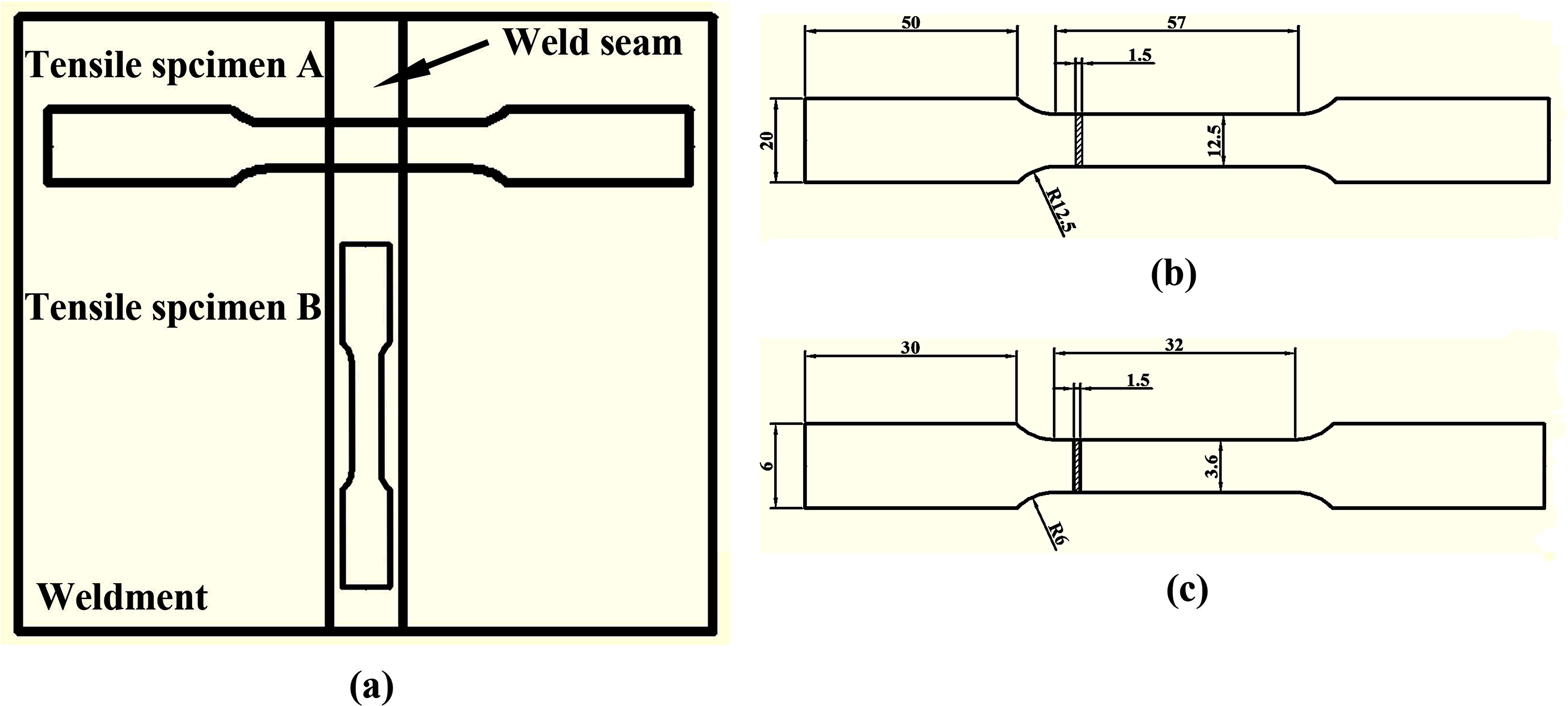
a positions of tensile specimens in weldment; b dimension of tensile specimen A in millimeters; c dimension of tensile specimen B in millimeters
Results
Macromorphologies of weld pools in the O/NSA-TIG welded AZ31 magnesium alloy joints
Figure 2 revealed the outlines of weld pools in O/NSA-TIG welded AZ31 magnesium alloy joints at different welding currents, and their D/W ratios were calculated and are shown in Fig. 3. Compared to O-TIG welding, the NSA-TIG welding effectively increased the welding penetration and D/W ratio. These two values increased rapidly with the increasing current at first, and then their growth slowed down when the current exceeded 110 A. Moreover, the defects of partial penetration, which appeared in welds, produced with low current decreased and even disappeared with the increasing current.
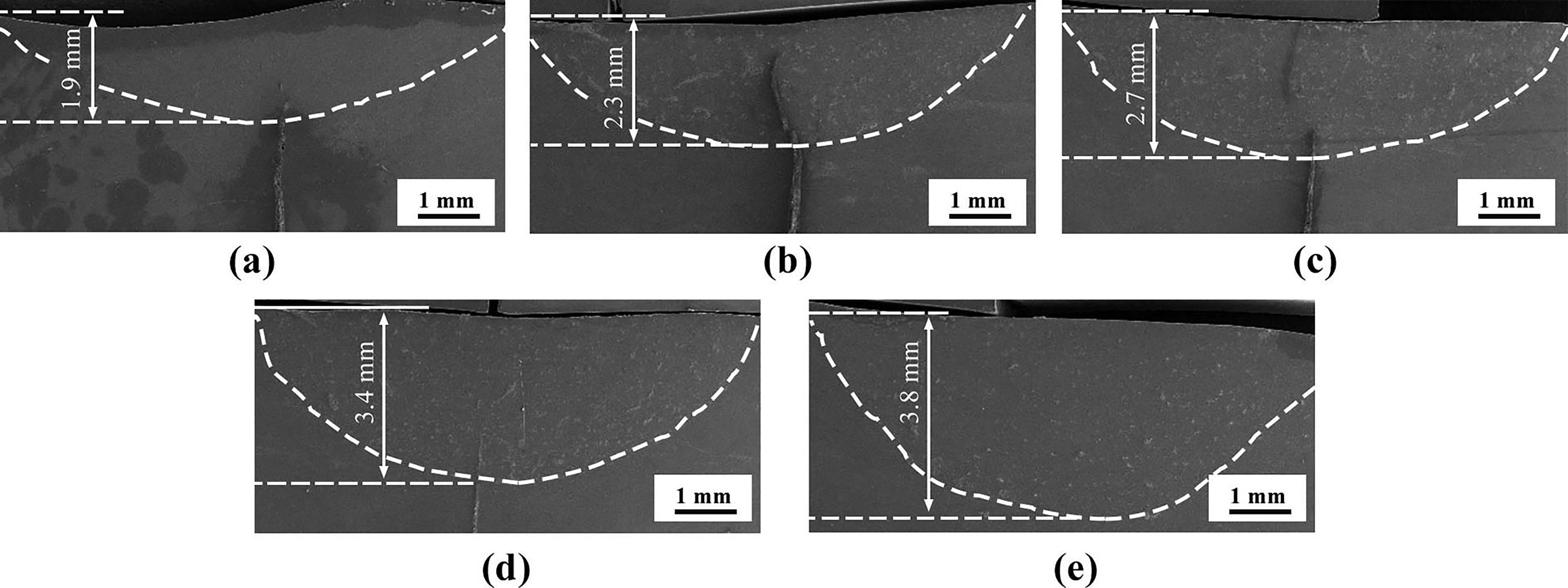
a O-TIG, 105 A; b NSA-TIG, 105 A; c NSA-TIG, 110 A; d NSA-TIG, 115 A; e NSA-TIG, 120 A
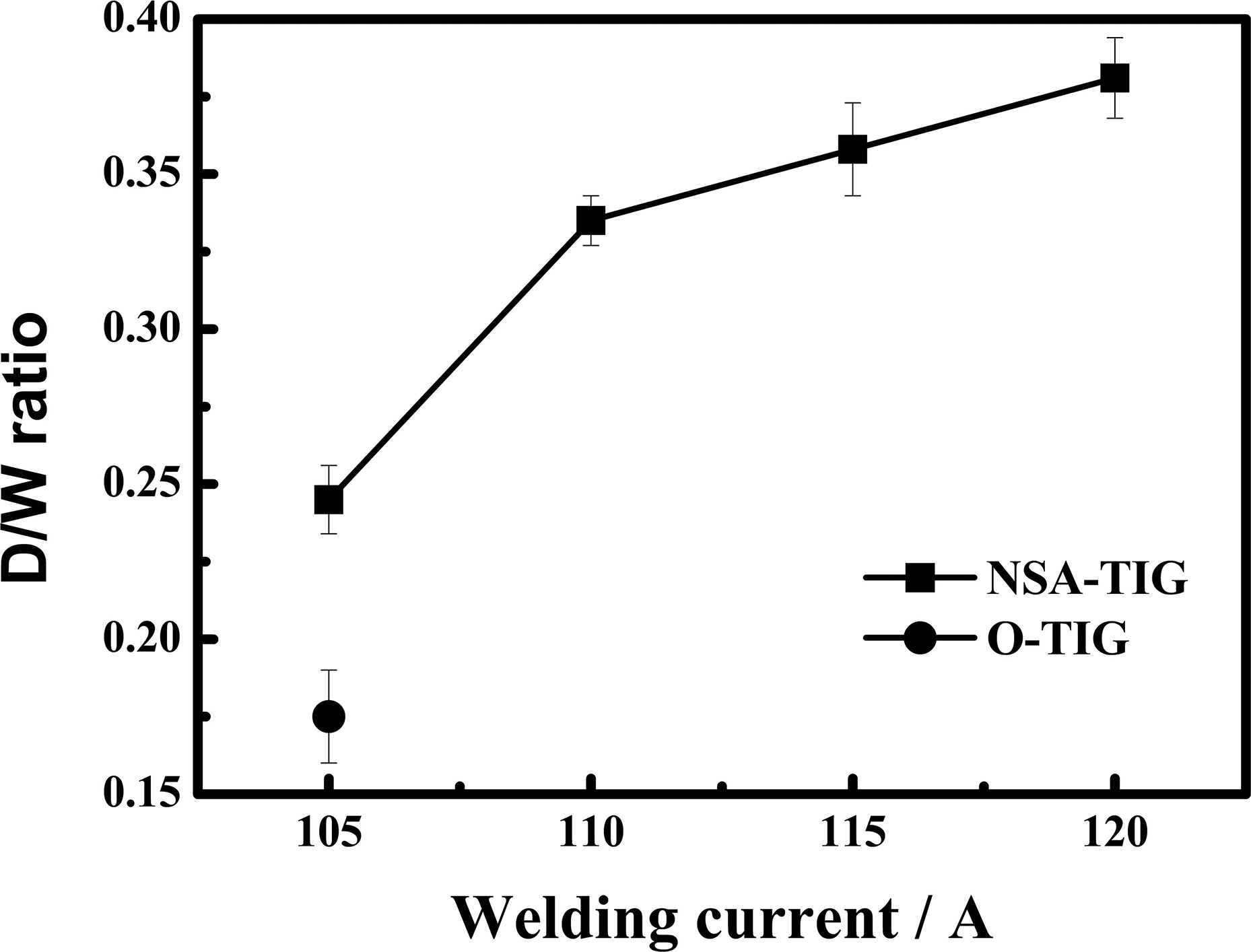
Depth/width ratios of weld pools in O/NSA-TIG welded AZ31 magnesium alloy joints produced with different welding currents
Microstructures of O/NSA-TIG welded AZ31 magnesium alloy joints
Figure 4a shows the microstructures of the FZ in the O-TIG welded AZ31magnesium alloy joints with welding current of 105 A, which was composed of the primary phase (marked with arrow A) and the second phase (marked with arrow B). In the FZ of the NSA-TIG welded AZ31 magnesium alloy joints, a dispersed phase (marked with arrow C) existed besides the primary and second phases (as seen in Fig. 4b). According to the EDS results and binary phase diagrams and other literature, 19 the primary phase, second phase and dispersed phase could be identified as α-Mg, β-Mg17Al12 and nano-SiC particles respectively. The EDS analysis results of phases A, B and C and phase identity in Fig. 4 were collected in Table 1.
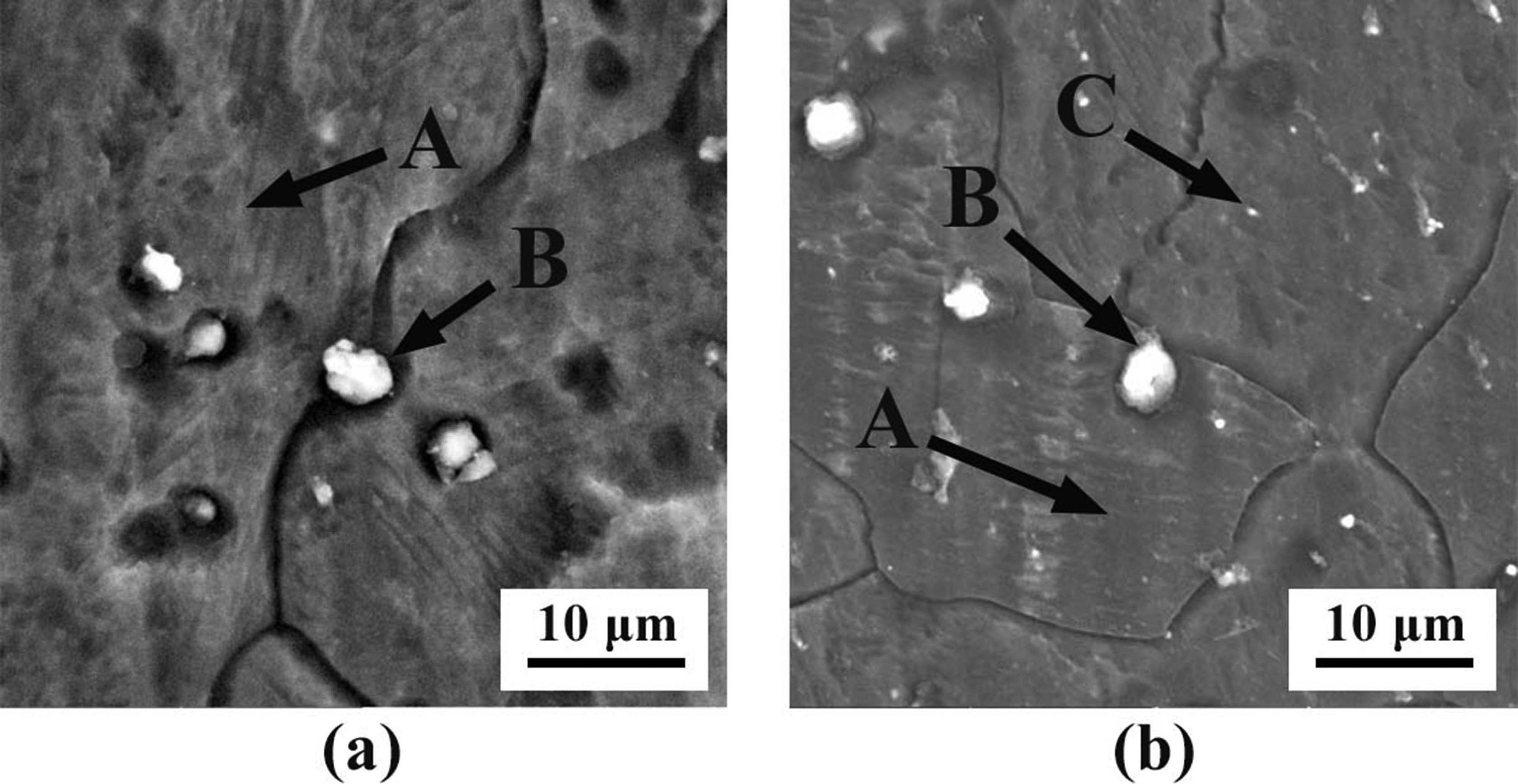
a O-TIG; b NSA-TIG
Analysis (EDS) results of phases A, B and C in Fig. 4
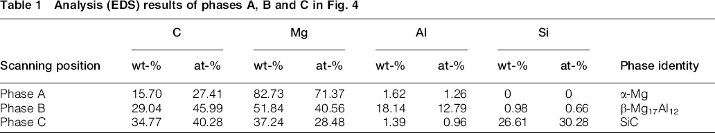
There is almost no Si element in AZ31 magnesium alloys, and SiC particles also almost do not decompose during the welding process because of their extremely high stability. 20 The reaction between some SiC particles and Mg might form a dash of Mg2Si particles, 21 but these Mg2Si particles were even smaller than SiC particles, and they distributed with the SiC particles in welding pool. Therefore, the distribution of Si element detected by SEM and EDS analysis could simply represent the distribution of nano-SiC particles in the NSA-TIG welded joints. The scanning area and the results are shown in Fig. 5, revealing that nano-SiC particles were mainly distributed in the centre and bottom zone of the welding pool (as seen in Fig. 5a). In welding pools of joints produced with other welding current values, the atom fraction of Si element was detected at positions same with those in Fig. 5a. The results showed that the distribution characteristic (mainly distributed in the centre and bottom zone in the welding pool) became further distinct with the increase in welding current (as seen in Fig. 6).
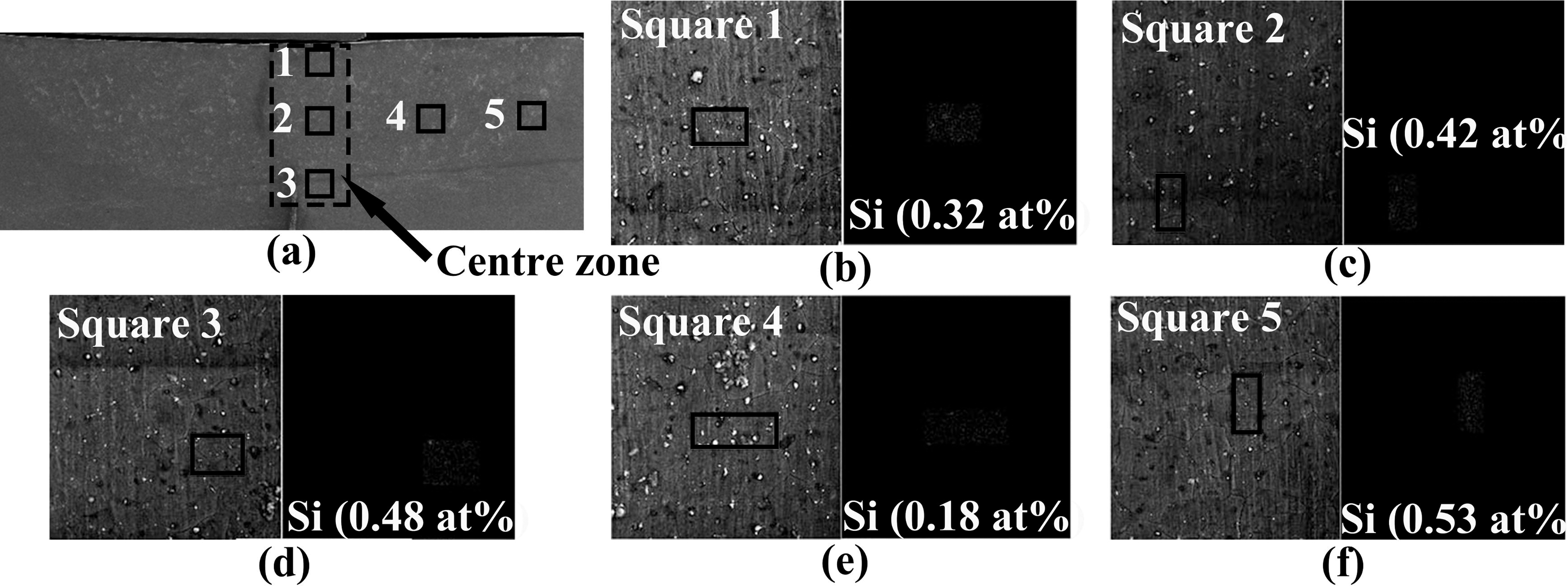
a detection positions in welding pool; b atom fraction of Si in square 1; c atom fraction of Si in square 2; d atom fraction of Si in square 3; e atom fraction of Si in square 4; f atom fraction of Si in square 5
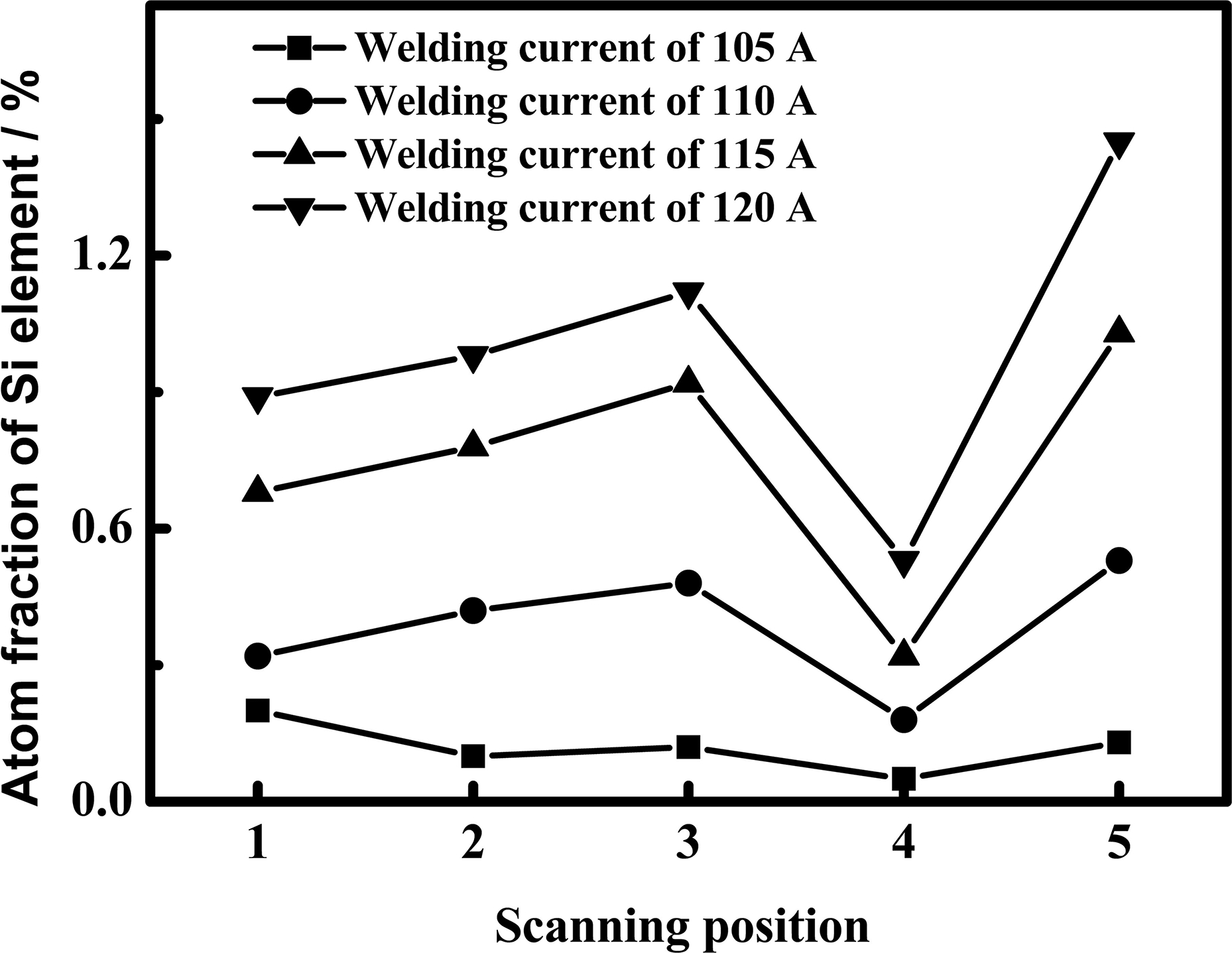
Distribution of Si element in welding pool of NSA-TIG welded joints with different welding currents
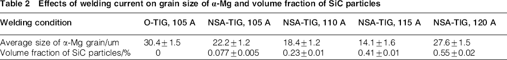
The average size of α-Mg grains in the FZ of the welding joints are showed in Fig. 7 and quantitatively analysed by an image analyser (UTHSCSA Image Tool 3.0), and the results were collected in Table 2. The average volume fraction of SiC particles were collected in Table 2, which were estimated from the average atom fraction of Si element from the detected area of the welding pool. It can be seen that the grain size of α-Mg in NSA-TIG welded joints was smaller than that in O-TIG welded joints with the same welding current of 105 A, and they decreased with the increasing welding current but increased rapidly when the current exceeded 115 A. In addition, the amount of SiC particles dispersed in the weld pool constantly increased with the increasing welding current in NSA-TIG welded joints.
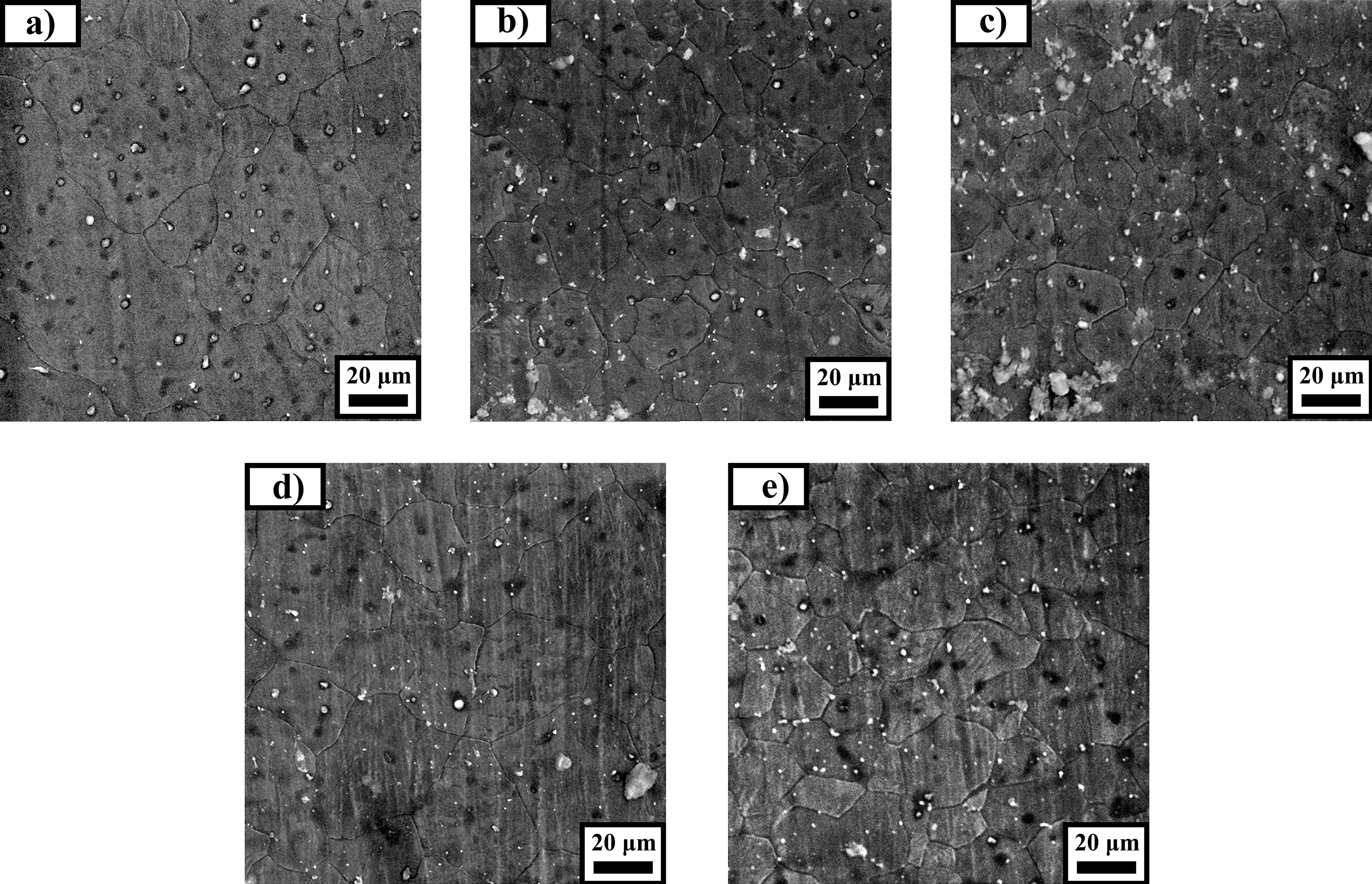
a O-TIG, 105 A; b NSA-TIG, 105 A; c NSA-TIG, 110 A; d NSA-TIG, 115 A; e NSA-TIG, 120 A
Effects of welding current on grain size of α-Mg and volume fraction of SiC particles
Mechanical properties of the O/NSA-TIG welded AZ31 magnesium alloy joints
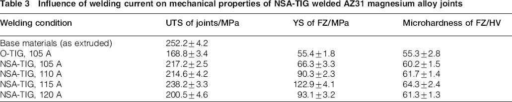
The relationship between the welding current and the mechanical properties of O/NSA-TIG welded AZ31 magnesium alloy joints is shown in Table 3. The UTS of NSA-TIG welded joints was higher than that of O-TIG welded joints with the same welding current of 105 A. It increased with the increasing welding current and then decreased when the current exceeded 115 A. Since all the tensile tests specimens fractured at the FZ of welding joints, the YS and microhardness tests were only conducted at the FZ, and the results demonstrated the same trend as the UTS tests results (as seen in Table 3).
Influence of welding current on mechanical properties of NSA-TIG welded AZ31 magnesium alloy joints
Discussion
Influence of welding current on macro/microstructure of NSA-TIG welded AZ31 magnesium alloy joints
The activating flux TiO2 added in NSA-TIG welding process increased the D/W ratio of welding pool by changing the surface tension temperature coefficient from negative to positive (as seen in Fig. 2).
22
Then, the increased welding current led to higher D/W ratio further because of more heat input, which could be described by the following formula
23
The distribution of SiC particles in the welding pool resulted from the combined effects of liquid metal flow and physical property of SiC particles. Figure 8 showed the distribution mechanism of SiC particles in the welding pool during NSA-TIG welding. Before the welding process, SiC particles were coated evenly on the surface of magnesium alloy plates (as seen in Fig. 8a). Then, the magnesium alloys were melted by the heat of welding arc and formed the welding pool, in which the liquid metal moved in the direction shown in Fig. 8b under the action of Marangoni flow. 24 According to Stokes's law,25, 26 the settling velocity of SiC particles was much slower than the speed of Marangoni flow, so the SiC particles were driven by the Marangoni flow and moved in the same path of Marangoni flow (as seen in Fig. 8b). Therefore, the SiC particles were mainly distributed in the centre and bottom region of the welding pool (the path of liquid metal flow) after it cooled to room temperature (as seen in Fig. 8c). Moreover, since the role as nucleation agents of SiC particles, the α-Mg grain refinement was achieved by NSA-TIG welding (as seen in Table 2). 17 The increasing welding current accelerated the liquid metal flow and therefore led more SiC particles to be distributed in the welding pool, refining the α-Mg grains further (as seen in Table 2). However, the size of α-Mg grains grew rapidly when the welding current exceeded 115 A because of the excessive heat input (Table 2).

Distribution mechanism of SiC particles in welding pool during NSA-TIG welding
Influence of welding current on mechanical properties of NSA-TIG welded AZ31 magnesium alloy joints
Five mechanisms, as follows, were considered to contribute to the strength levels of the NSA-TIG welded AZ31 magnesium alloy joints.
(1) Grain refinement strengthening (2) Dispersion strengthening (a) Orowan strengthening can be evaluated by the following formula
30
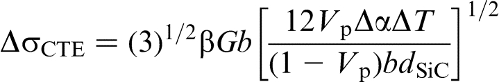
(b) Strengthening is induced by the difference of coefficient of thermal expansion between nano-SiC particles and matrix, which could be described by the following formula
31
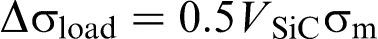
(c) Strengthening induced by the load transfer from the matrix to the nano-SiC particles could be described by the following formula
32
The contribution of grain refinement to the YS can be evaluated by the Hall–Petch formula as follow
27

Being dispersed into welded joints in NSA-TIG welding, the nano-SiC particles inhibit dislocation move under tensile loads and therefore improve the joint strength. According to strengthening mechanism models for metal matrix composites,28, 29 their effects mainly included
Thus, the strengthening effects of nano-SiC particles on the NSA-TIG welded joints could be evaluated by following equation
33

Conclusions
The effects of welding current on the macromorphologies, microstructures and mechanical properties of the NSA-TIG welded AZ31 magnesium alloy joints were investigated. Main findings of this work were as follows.
With the same welding parameters, the NSA-TIG welded AZ31 magnesium alloy joints had deeper weld penetrations, narrower weld widths, less welding defects and smaller α-Mg grains in FZ than those produced by welding. These effects were intensified by increasing welding current. Obeying the Stokes's law, the nano-SiC particles were driven to move along the path of the liquid metal flow (Marangoni flow) in the welding pool during the NSA-TIG welding process. As a result, they were mainly distributed in the centre and bottom zone of welding pool. The NSA-TIG welded AZ31 magnesium alloy joints were strengthened by the SiC particles through grain refinement strengthening and dispersion strengthening. Higher welding currents increased the SiC particles amount in welding pool and improved the joint strength further except for the much heat inputted when the welding current exceeded 115 A.
Acknowledgement
This project is supported by a National Natural Science Foundation of China (grant no. 51375511).