
Abstract
Conventional gas metal arc welding of modified 9Cr–1Mo steels referred to as P91 steels is considered difficult due to loss of alloying elements and degradation of weld joint properties. In comparison to the conventional process, pulsed current gas metal arc welding allows more accurate control of heat input per unit length and electrode deposition and, thus, can be more suitable for the joining of P91 steel. A detailed experimental study is therefore undertaken to examine the roles of welding current, speed and groove angle in the weld bead profiles and joint properties in multipass pulsed current gas metal arc welding of 12 mm thick P91 steel. The results show that the joint properties are strongly influenced by the heat input per unit length and the groove angle. A groove angle of 75° and an appropriate choice of process conditions resulted in fairly acceptable bead profiles and joint properties.
Keywords
Introduction
The creep strength enhanced ferritic steels contain 9–12%Cr, small amounts of Mo, V, and Nb, and varying additions of W, Co, B, N, and Ni.1–3 The modified 9Cr–1Mo grade steel that is referred to as P91 steel belongs to the family of creep strength enhanced ferritic steel and is a promising material for high temperature piping components in modern power plants.1–7 However, the weldability of P91 steel is a major concern due to the loss of alloying elements, degradation of weld joint mechanical properties, its susceptibility to type IV cracking1–6, 8, 9 and the formation of delta ferrite.5, 10–13 A careful control of the heat input per unit length and suitable choice of welding procedure, technique and post-weld heat treatment (PWHT) cycles are reported to minimise some of these problems.8–11, 14–17 Furthermore, reducing the level of non-metallic inclusions and weld metal oxygen content is found to improve weld toughness in welds of P91 steels with consumable electrodes.1, 7, 11, 12
Several processes are attempted for joining of P91 steels depending on the original joint geometry, welding position, and the required rate of electrode deposition.1, 2, 14, 18, 19 Gas tungsten arc welding (GTAW) could provide the joint toughness of around 100 J at room temperature although the lower rate of filler metal deposition remained a concern.1, 2, 13, 14, 18, 19 Conventional welding processes with consumable electrode could improve the deposition rate, but the welds commonly suffered from loss of alloying elements, low toughness, and high level of oxygen content and non-metallic inclusions.13, 14, 18–22 Newell reported severe lack of fusion (LF) and oxide inclusions in conventional gas metal arc welding (GMAW) of P91 steels with a solid wire electrode. 23 The author could reduce the level of inclusions using the metal cored wire electrode. 12 Laser beam welds in P91 steel could improve the joint toughness due to fine microstructure and reduce the size of (HAZ), but the formation of delta ferrite remained a concern.10, 24 Kundu et al. 25 reported the presence of high tensile residual stress especially in the region susceptible to type IV cracks in electron beam welds of 9 mm thick P91 steels. Albert et al. 13 proposed that a reduction in the HAZ width could enhance the creep rupture life. Rothwell and Abson 15 reported smaller residual stress and distortion in electron beam welding of 28 mm thick pipes of P91 steel. Aravinda et al. 26 used GTAW of P91 steel with hot- and cold-wire electrodes and found significant deterioration of weld joint impact toughness with the hot-wire fed GTAW process. The use of an advanced GTAW process with activating flux on the workpiece surface, referred to as A-TIG, showed the presence of delta ferrite in welds of P91 steel. 27 In summary, appropriate welding schedule with consumable electrodes has consistently remained a challenge for the joining of medium to thick P91 steels.
Pulsed current gas metal arc welding (GMAW-P) has advanced significantly to facilitate high electrode deposition rate with accurate control of heat input by the use of current pulses at moderate to high frequency.28, 29 GMAW-P of (HSLA) steels could provide superior tensile, impact and fatigue properties over the other conventional joining techniques. 30 However, the application of GMAW-P for the joining of medium to thick P91 steels in single-pass and multipass is rare. In comparison to the conventional process, GMAW-P could reduce HAZ width, weld porosity and facilitate favourable weld microstructure and mechanical properties.30, 31 A recent study on single-pass GMAW-P of P91 steel showed a fair improvement of the weld chemistry and mechanical properties over the similar joints prepared using conventional GMAW. 32
A detailed investigation on multipass GMAW-P of 12 mm thick P91 steel is undertaken in the present work. The effects of welding current, speed and groove geometry on the bead profile, weld chemistry and oxygen content, weld toughness and tensile strengths and susceptibility to the formation of delta ferrite and non-metallic inclusions are examined. The multipass weld cross-sections are examined critically for adequacy of the side-wall and inter-bead fusions. The hardness distribution is tested across the weld and HAZ regions both in as-welded and after PWHT.
Experimental investigation
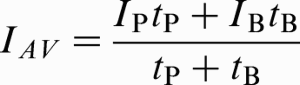
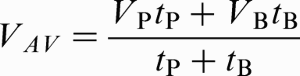
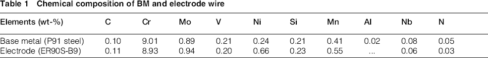
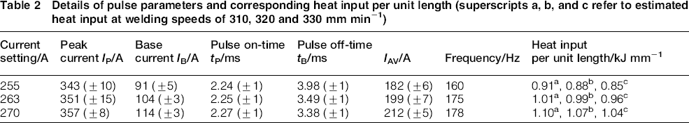
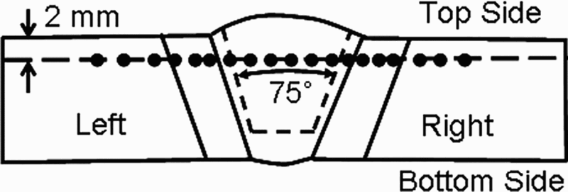
Table 1 presents the composition of workpiece and electrode materials. The base material conforms to 12 mm thick modified 9Cr–1Mo (P91) steel with impact toughness, ultimate tensile strength and yield strength of respectively 220 J, 670 MPa and 550 MPa at room temperature. Figure 1 schematically shows the joint geometry. Multipass bead-in-groove welds are prepared in flat (1G) position with Ar+2%CO2 shielding gas using a backhand technique at multiple combinations of current, speed and groove angle following a three-level full factorial design with three repetitions at each welding condition. Three levels of welding speed and current setting are chosen as follows: 310, 320, and 330 mm min− 1 and 255, 263, 270 A respectively. Three different groove angles of 45°, 60° and 75° are considered as shown in Fig. 1. A microprocessor controlled synergic GMAW-P power source is used to prepare the weld samples. A four-channel transient recorder (Graphtec made, model no. GL 900-4) with simultaneous sampling rate of 0.1 MHz is used to monitor the current and the voltage transients. The corresponding time-averaged current IAV and voltage VAV are estimated as
Chemical composition of BM and electrode wire
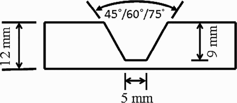
Schematic view of groove geometry for sample multipass welds
Details of pulse parameters and corresponding heat input per unit length (superscripts a, b, and c refer to estimated heat input at welding speeds of 310, 320 and 330 mm min− 1)
The welded coupons were subjected to PWHT for stress relieving at 760 ± 10°C for 4 h. The transverse weld cross-sections were examined after polishing and etching with Villella's reagent (1 g picric acid, 5 mL hydrochloric acid, and 100 mL methanol). The bead microstructures are examined under a scanning electron microscope (SEM) in as-welded condition and after PWHT. The microhardness distribution was measured in as-welded condition and after PWHT at various locations as shown in Fig. 2. The tensile strength was evaluated using all-weld sub-size specimens as per ASTM E8:2013. 33 The weld toughness was evaluated using sub-size specimens as per ASTM A370:2014. 34 A spectrometer based weld bead chemical analysis was carried out as per ASTM E415:2014. 35 The oxygen content in the weld was studied by wet analysis following ASTM E1019:2011. 36 The weld inclusion level was examined using energy dispersive spectroscopy analysis.
Locations for measurement of microhardness distribution
Results and discussion
Figure 3a–c shows the transverse weld macrographs for the three groove angles of 45°, 60° and 75° for a given welding condition. In each case, the number of requisite passes to fill the groove is shown by black lines. Although the number of required passes is the same as six for both the 60° and 75° groove angles, the corresponding bead profiles differ significantly (Fig. 3b and c). The bead width and height are measured to be 8.0 and 6.5 mm and 9.5 and 5.5 mm respectively for the 60° and 75° groove angles. The wider and thinner weld beads with the 75° groove angle could facilitate efficient bead tempering and improve weld toughness as commonly noted in multipass welds.1, 23 Furthermore, the macro-examination of the weld coupons show LF of the side walls for several cases with the 45° and in few cases with 60° groove angles. Figure 3d shows the presence of an LF defect in a typical weld cross-section with the 60° groove angle. However, all the weld coupons with the 75° groove angle exhibited sound bead profiles without any LF defect. Although a higher groove angle such as 75° would result in a nominal increase in the deposit volume, the elimination of the LF defect is considered to be a significant achievement in multipass GMAW.1, 21, 37
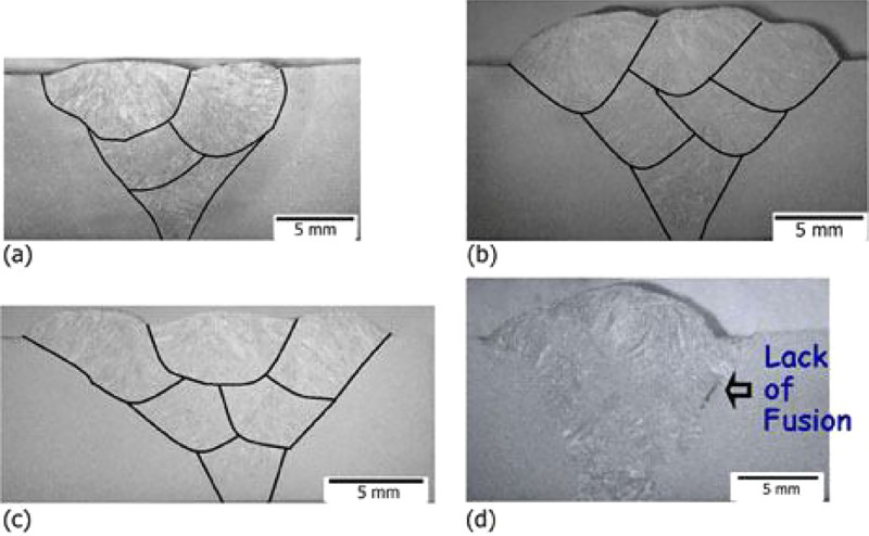
Macrographs of weld transverse sections at welding speed of 320 mm min− 1 and current setting of 263 A at groove angles of a 45°, b 60°, c 75° and d 60° showing typical LF defect
Table 3 shows the measured weld metal chemical composition (in wt-%) and indicates no appreciable loss of the alloying elements for the range of welding conditions considered here. The chemical analysis is conducted for different weld passes in order to verify the consistency of the measured results. The weld metal oxygen content was found to be in the range of 490 to 530 ppm that is significantly lower than the same reported in P91 welds with conventional GMAW (∼780 ppm) 23 , (FCAW) (600–980 ppm)11, 22 and (SAW) (∼580 ppm) 23 processes. The measured values of the weld metal compositions are utilised to estimate the corresponding values of chromium equivalent (Creq) and the Kaltenhauser ferrite factor (KFF) that provide a measure of the tendency to ferrite retention and delta ferrite formation in weld.1, 5, 11 The recommended maximum values of Creq and KFF to avoid delta ferrite are respectively specified as 10 and 8 in the contemporary literature. 7 The estimated values of Creq and KFF of the P91 sample welds remain in the range of respectively 7.45 to 7.52 and 4.55 to 4.84 that indicates little chance of delta ferrite formation.
Weld metal compositions (in wt-%) in GMAW-P
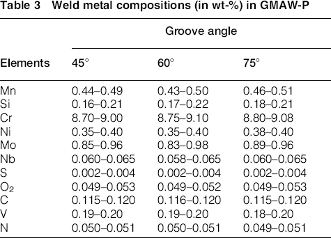
Figure 4a and b shows the microstructure of the base metal (BM) and fusion zone (FZ) in as-welded condition for a sample P91 weld, while Fig. 4c–f show the microstructures of the FZ and HAZ after PWHT at 760°C for 4 h. The microstructure of the base material consists of tempered martensite with small precipitates of carbide particles within and around the prior austenite grain boundaries (Fig. 4a). Figure 4b shows the presence of freshly formed martensite in a typical as-welded microstructure of the FZ before PWHT. The FZ microstructure after PWHT is devoid of any trace of delta ferrite and depicts a uniform and distinct distribution of carbide precipitates in the tempered weld (Fig. 4c). The HAZ in the welds of P91 steel commonly consists of coarse grain (CGHAZ), fine grain (FGHAZ) and inter-critical (ICHAZ) regions. 1 The CGHAZ starts from the FZ boundary and experiences peak temperature well above the Ac3 temperature. As a result, the carbides that impede the austenite grain growth gets dissolved resulting in coarse austenite grains and transforms to martensite on cooling. 1 Figure 4d shows a similar microstructure of the CGHAZ with coarse prior austenitic grains. The FGHAZ undergoes a peak temperature just above the Ac3 temperature resulting in fine prior-austenite grains as shown in Fig. 4e. The ICHAZ is the furthest from the FZ boundary and experiences a peak temperature between Ac1 and Ac3 resulting in partial transformation of austenite. Figure 4f shows a mixture of austenite–martensite phases in the ICHAZ microstructure. Similar FZ and HAZ microstructures in welds of P91 steel are also observed in GTAW, SMAW and SAW processes.1, 7–11
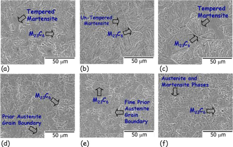
a Base metal, b FZ in as-welded condition, and c FZ, d CGHAZ, e FGHAZ, and f ICHAZ microstructures after PWHT at 760°C for 4 h for sample welds at current setting of 263 A, welding speed of 320 mm min− 1 and groove angle of 75°
The variation in FZ and HAZ microstructures is examined further by the characteristic microhardness distribution across the P91 welds before and after PWHT. Figure 5 shows the FZ microhardness to be higher compared to that in base material and HAZ regions in as-welded condition. The FZ depicts a cast structure in the as-welded condition leading to higher hardness in comparison to the same in the normalised and tempered structure of the base material. 10 The microhardness becomes nearly uniform after PWHT except a softer region in ICHAZ due to partial transformation of austenite structure and subsequent tempering during PWHT. 1 The overall width of the HAZ remains between 3.0 and 3.5 mm in contrast to 4.5 to 5.0 mm as observed in GTAW and SMAW of P91 steels. 14 The reduction in HAZ width in GMAW-P can be considered significantly beneficial towards reducing the susceptibility to type IV cracking in welds of P91 steel.1, 13
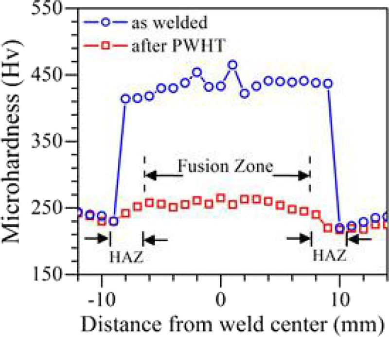
Microhardness variation across weld bead at current setting of 263 A, welding speed of 320 mm min− 1 and groove angle of 75° in as-welded condition and after PWHT
The weld bead toughness for each sample weld is evaluated at three different locations as shown in Fig. 6a to examine the consistency of the measured values across the weld bead. In general, the toughness along location 1 are found to be slightly higher that is attributed to the effective tempering of this region during subsequent weld passes and resulting finer microstructure. Figure 6b shows the effect of heat input per unit length on the average weld bead toughness (at +20°C) for different welding conditions. The weld bead toughness is found to reduce with an increase in the heat input per unit length for the 75° and 60° groove angles. The measured toughness values for the welds with the 45° groove angle are not plotted as the same are found to be scattered within a range of 42 to 55 J that is attributed to the large number of defects in these welds. The decrease in the weld toughness with an increase in the heat input per unit length is attributed primarily to the reduced cooling rate and resulting coarser grain structure. Further, the weld bead toughness is found to increase with an increase in the groove angle for a given heat input per unit length that is attributed to the decrease in weld defects at higher groove angles. The weld bead toughness is also affected by the size and density of the micro-inclusions in the bead microstructure. Figure 7 shows the distribution of spherical micro-inclusions with Al, Si, Mn and Fe respectively around 5.96%, 5.77%, 7.86% and 79.59% as obtained from an SEM–energy dispersive spectroscopy analysis. An inclusion rating analysis as per ASTM E-45:2013 38 has shown that the size of these inclusions is lesser than 2 μm that is significantly lower than those obtained in FCAW 11 and single-pass GMAW-P. 32 The smaller size of inclusions in multipass GMAW-P of P91 welds is attributed to the remelting of the underneath weld beads during multiple weld passes and resulting disintegration of the coarser micro-inclusions and formation of numerous finer particles.
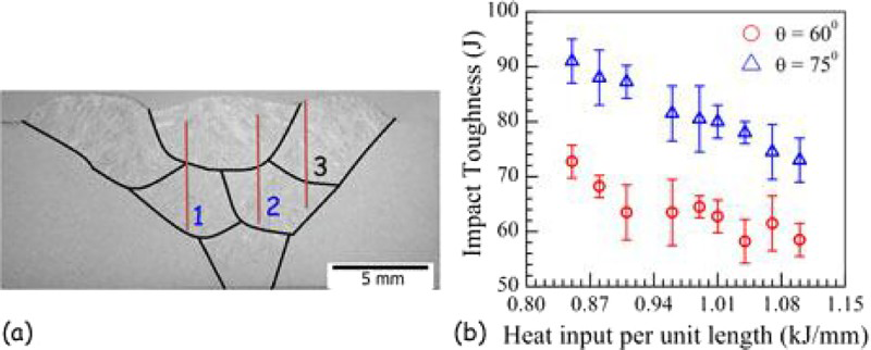
a Notch locations for weld toughness measurement, b measured values of weld toughness as function of heat input per unit length and at two different groove angles of 60° and 75°
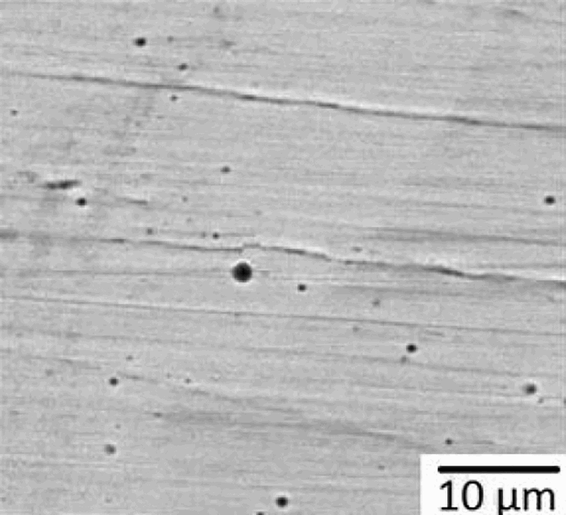
Micrograph (SEM) of weld showing inclusion distribution for current setting of 263 A, welding speed of 320 mm min− 1 and groove angle of 75° in as-welded condition
Figure 8 presents the all-weld tensile strength of the sample welds. The measured ultimate tensile strength (UTS) indicates a similar trend as noticed in the weld bead toughness in Fig. 6b. The measured values of UTS reduce with an increase in the heat input per unit length for the welds made with the 60° and 75° groove angles. In contrast, the measured strengths for the welds produced with 45° groove angle exhibited a wide scatter in between 650 and 720 MPa that is attributed to the inherent defects and were not plotted. The maximum all-weld UTS is obtained as 760 MPa with the 75° groove angle for a current setting of 255 A and welding speed of 330 mm s− 1 that conforms to a low heat input per unit length of 0.85 kJ mm− 1. An increase in all-weld UTS at lower heat input per unit length can be attributed to the smaller dendrite sizes and lesser inter-dendritic spacing in the FZ.
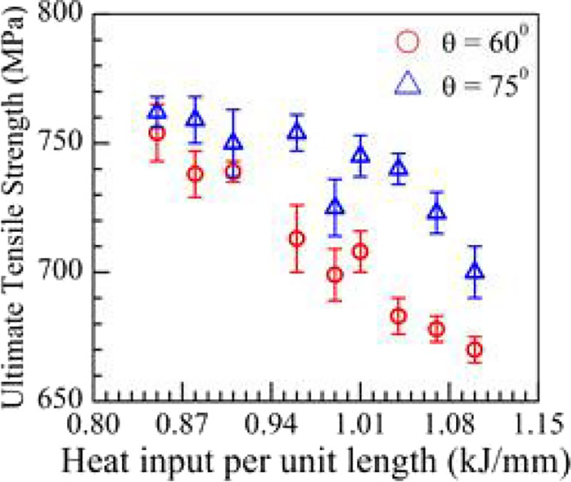
Measured values of weld bead ultimate tensile strength as function of heat input per unit length and at two different groove angles of 60° and 75°
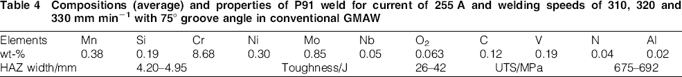
An attempt is made further to evaluate multipass welds in 12 mm thick P91 steel with a 75° groove angle using conventional GMAW at a current setting of 255 A and welding speeds of 310, 320 and 330 mm s− 1 as similar conditions in GMAW-P have provided better welds. The corresponding values of heat input are estimated as 1.369, 1.297 and 1.243 kJ mm− 1 in conventional GMAW compared to 0.91, 0.88 and 0.85 kJ mm− 1 in GMAW-P (Table 2). Table 4 shows the measured values of average weld metal composition and the ranges of HAZ width, toughness and all-weld UTS for the welds made using conventional GMAW. A comparison of Tables 3 and 4 shows relatively greater loss of alloying elements, e.g. Mn, Cr, Ni and Mo, and higher weld metal oxygen content in conventional GMAW compared to that in GMAW-P. The measured HAZ width in conventional GMAW is found to be in the range of 4.20–4.95 mm in contrast to 3.0–3.5 mm in GMAW-P. The ranges of weld bead toughness and all-weld UTS in conventional GMAW are respectively 26–42 J and 675–692 MPa that are far inferior to those obtained in GMAW-P for similar welding conditions (Figs. 6 and 8). The reduced loss of alloying elements, smaller HAZ width and superior weld properties in GMAW-P of P91 steels are attributed primarily to the pulsating nature of current and voltage and the resulting decrease in effective heat input in comparison to that in conventional GMAW.
Compositions (average) and properties of P91 weld for current of 255 A and welding speeds of 310, 320 and 330 mm min− 1 with 75° groove angle in conventional GMAW
The role of the key welding conditions such as current, speed and groove angle in the bead morphology and joint properties in multipass GMAW-P of P91 steels are studied in detail that have been scarce in the literature. The present work shows that P91 steels can be welded in multipass GMAW-P with fairly acceptable bead morphology and joint properties at high welding speed and electrode deposition rate in comparison to the conventional GMAW, FCAW and SMAW processes.
Conclusion
GMAW-P facilitates a more accurate control of the heat input per unit length compared to the conventional GMAW and a greater rate of electrode deposition than GTAW with external electrode wire and does not pose flux related problems similar to SMAW, FCAW and SAW processes. A detailed investigation of the suitability of GMAW-P for the joining of P91 steels is therefore requisite and currently scarce in the literature. The work presented here demonstrates a critical examination of the effects of the key welding variables on the final weld bead quality in multipass GMAW-P of 12 mm thick P91 steel. The welds are found to be fairly acceptable based on the visual inspection of the bead profile, composition analysis, oxygen and inclusion levels, and the examination of microhardness distribution, microstructure, mechanical strength and toughness. An appropriate selection of the heat input per unit length and groove geometry is found to be critical. In particular, the groove angle should be sufficiently large to get a defect free weld. An average heat input per unit length of 0.85 kJ mm− 1 with a groove angle of 75° provided the best results.