
Abstract
The purpose of this study is to investigate the evolution of residual stress during designing a 89-pass narrow gap welding of nuclear rotor pipes. A two-dimensional finite element model is employed to calculate the residual stress in welding process and heat treatment process, and then the evolution of residual stress during the welding process was discussed in detail. The investigated results show that the overall trend of hoop stress on the inner surface decreases gradually before pass 30, while the trend remains unchanged after pass 30. The through wall axial residual stress at the weld centreline demonstrates a distribution of bending type before pass 38, while this bending type distribution turns into a clearly self-equilibrating type after pass 38.
Keywords
Introduction
In recent years, the circumferential butt welding is widely used for the engineering applications and may be the most common types of joining process in nuclear rotor steel pipe systems. The presence of tensile residual stress has been considered as an important factor that increases the susceptibility of the welded joints to fatigue damage, stress corrosion cracking and even fracture. 1 Therefore, it is extremely important to research the distribution and the evolution of welding residual stress during the welding process for profiting the structure design and evaluating the service lifetime of the welded components. 2
Experimental measurement of residual stress during welding has some practical limitations, and the experimental measurement can be conducted commonly after the whole welding process has been complete or after post-weld heat treatment (PWHT).3, 4 Owing to the relatively large wall thickness in nuclear rotor piping systems, the welded joints are often constructed of a large number of weld passes. At this time, it is difficult to determine the distribution and evolution of residual stress states during welding by experiment. The most effective method to research the residual stress is combining the numerical simulation with the experimental measurement.5–9 Lindgren 10 gave a detailed review of the pervasive application of analysing the thermal and mechanical effects of welding by finite element (FE) method from the 1970s to 2003. Welding residual stress and variation of welding stress in welded structures have been simulated and predicted by various analytical and computational approaches.11, 12
It is commonly considered sufficient to simulate a welded pipe using a two-dimensional (2-D) axisymmetric FE model instead of a three-dimensional (3-D) model, which is faster and easier to investigate, and which has been adopted throughout this study.13–15 A 2-D axisymmetric model was developed to analyse the residual stress of butt welds in stainless steel pipes with different weld passes and wall thicknesses.16, 17 Dong 18 introduced a large number of 2-D axisymmetric models to study the effects of various welding procedure parameters and joint geometry on through thickness residual stress distributions. In general, the shape of final residual stress depends on several main factors such as structural dimensions (especially the wall thickness over diameter ratio), heat input, the number of weld passes, welding sequence and restraint conditions.19–21 In addition, Tan et al. 22 developed a not lumped model and two lumped pass models to study the effect of the lumped pass simulation on the distribution of residual stresses before and after heat treatment in a thick walled nuclear power rotor pipe.
A lot of attentions have been paid to the stress evolution of large thickness welded structures in recent years, and significant progress has been obtained. Zhang et al. 23 analysed the interpass stresses during double sided double arc multipass welding process, which showed that the stresses of the first and last pass were higher than those of other passes. Liu et al. 24 investigated the distribution and evolution of through wall residual stress during multipass narrow gap welding of thick walled stainless steel pipes. Tan et al. 25 introduced three FE models to investigate the effect of geometric construction on the distribution of residual stresses before and after heat treatment in designing a nuclear welded rotor. Overall international researchers are more interested in final residual stress state, other than stress evolution. However, the interpass stress during welding may be higher than the final stress and the formation process of residual stress is very important to the safety of nuclear rotor. Moreover, the process and distribution of the residual stress evolution during multipass welding should be investigated clearly to further develop a mitigation technique for structure design. Therefore, understanding the distribution of the as welded stress in detail, achieving the process of the residual stress evolution clearly during multipass welding, and finding the variation of the residual stress before and after PWHT are indeed necessary for structure design and engineering application.
In the present work, an FE computational procedure is employed using a 2-D axisymmetric FE model to simulate the temperature fields, the residual stress field distribution and the effect of PWHT during multipass narrow gap girth welding of a thick walled nuclear rotor steel pipe. The effectiveness of the FE modelling procedure was validated by experimental measurements. During simulation, the welding process associated with the multipass welding was performed by a detailed pass by pass simulation, and then the evolution of residual stress contours through wall residual stress, residual stress on the inner surface and residual stress at root bead during welding the process was discussed.
Experimental and numerical procedure
The nuclear rotor steel material investigated in this study is 20Cr2NiMo pipe with an outer diameter of 1980 mm, a wall thickness of 150 mm and a total length of 400 mm. The pipes were narrow gap multipass butt welded using tungsten inert gas welding for weld passes 1 to 9 and submerged arc welding for weld passes 10 to 89. During the experiments, the preheat temperature was 200°C. The welding specifications for each bead are listed in Table 1. After the whole welding process, the pipe was heat treated to reduce residual stress and improve the toughness in the welded joints. The nominal chemical compositions of the welded joints are summarised in Table 2. The dimensions of the welded pipe and the profile of the welded joints were given in Fig. 1. In the heat treatment process, the temperature and time curve for PWHT are shown in Fig. 2. After PWHT, the local removal blind hole method was employed to measure the internal residual stress of the thick walled pipe. 25
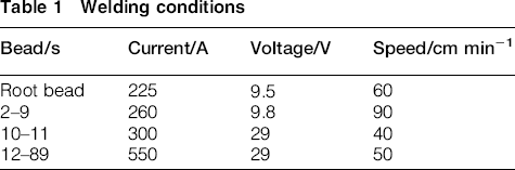
Welding conditions
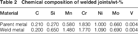
Chemical composition of welded joints/wt-%
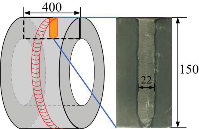
Welded pipe and fusion zone profile (unit: mm)
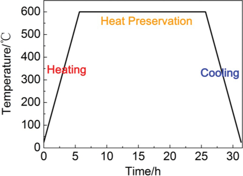
Heat treatment process
Figure 3 depicts an enlarged view of the FE model in the weld seam, and thermoelastic–plastic FE analysis procedure associated with the multipass welding simulation was reported in detail by Tan et al. 25 . In the FE simulation, both the temperature dependent thermal and mechanical of rotor properties had been considered. Figure 4 shows the temperature dependent properties, which are assumed to be same in the weld metal and parent metal.
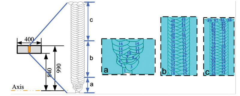
Axisymmetric FE analysis model
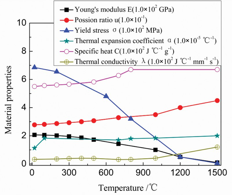
Temperature dependent material properties used in FE analysis
In the PWHT process, creep was assumed to obey the Norton power law and represented in the following equation:
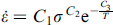
 is the creep strain rate; σ is the stress; T is temperature; and C1, C2 and C3 are constants respectively. Creep parameters26, 27: C1 = 4.40 × 10− 28, C2 = 4.312, C3 = 27912.
Simulated results
Simulated temperature
Figure 5 shows the temperature distribution directly after completely heating the 1st and 45th weld passes. From Fig. 5, it can be seen that the temperature contours indicate the regions that get heat affected and the fusion boundaries, and the peak value of temperature in the weld seam is higher than 1500°C. From the simulated boundary of the molten zone, a reasonable distance to the heat affected zone (HAZ) is obtained to be ∼3–4 mm in the present study. It can also be concluded that reasonable size of the molten region and HAZ size are captured from the temperature contours.
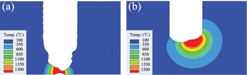
Temperature contours after completely heating of particular welded pass: a pass 1; b pass 45
Evolution of residual stress distribution
The hoop stress and axial stress development during the welding process obtained by the FE model are shown in Fig. 6a and b respectively. From Fig. 6a, it can be observed that the hoop stress is always tensile stress in the weld area, and the hoop tensile stress on the outside surface is larger than that on the inside surface with the growth of the weld seam. After completion of pass 20, the peak hoop tensile stress (∼761 MPa, the magnitude is slightly larger than the yield strength of the material at room temperature) appears in the outer surface region of the pipe. Two zones with hoop compressive stress occur in the parent metal areas adjacent to weld seam. With the increasing of the weld passes, the compressive area increases gradually, and the peak value of hoop compressive stress (∼370 MPa) is obtained at the last pass in the internal of the pipe.
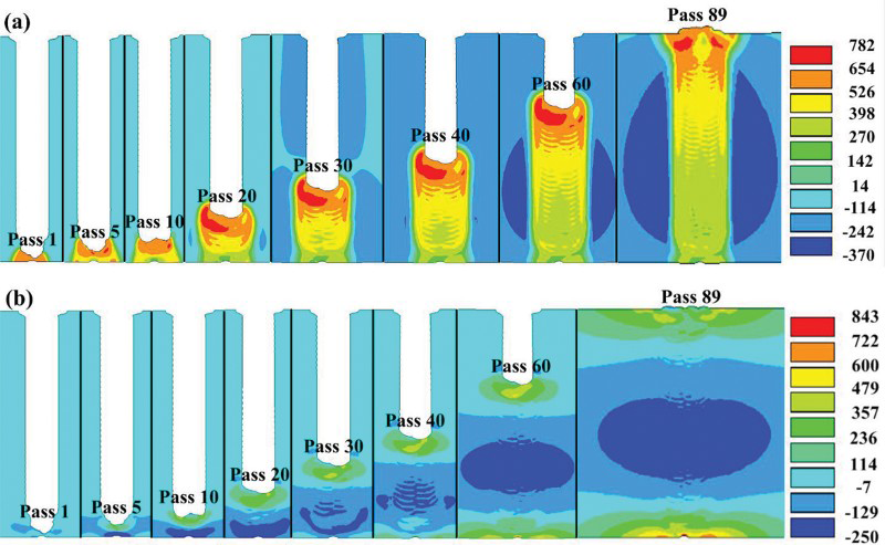
Residual stress contours (MPa) development during welding process: a hoop stress; b axial stress
From Fig. 6b, before pass 30 deposited, the axial stress of outside surface of the pipe is tensile stress, and that of inside surface is compressive stress. While after pass 40, on the inside and outside surface of the thick walled pipe, large axial tensile stress can be observed, and the peak value of tensile stress (843 MPa) appears in the TIG root bead near the inner surface, which is larger than the yield strength of the parent metal at room temperature. To balance the large axial tensile stress, a zone with axial compressive stress is generated in the internal of the pipe, and then this stress distribution maintains till the completion of the whole welding process.
Effect of PWHT
Figure 7 describes the residual stress after complete cooling to ambient temperature of PWHT, which reflects the high tensile stress distribution parts of both the hoop stress and the axial stress fields. By comparing Fig. 6 with Fig. 7a, it can be seen that the simulated highest tensile residual stress (761 and 843 MPa for hoop stress and axial stress respectively) after PWHT are reduced to approximately one-eighth their original values. Under the influence of PWHT, the distributions of the high tensile stress profile in the welded joints become more even. Therefore, it can be seen that PWHT can relieve the residual stresses significantly, and the heat treatment temperature (600°C) and holding time (20 h) of PWHT process are also extremely reasonable.
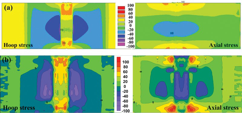
Hoop stress and axial stress contours (MPa) after PWHT: a simulated stress; b experimental stress 25
Comparing simulated residual stress contour with the experimental stress contour after PWHT of the pipe in Fig. 7, it can be concluded that the measured results match well with the simulated residual stress, except small difference occurs between the simulated residual stress and the measured one at the weld region. 25 Nevertheless, the residual stress distribution trends along the axial direction after PWHT can be captured with the simulation results, and experimental results showed good agreement with the simulated one. Figure 8 shows the distribution of simulated residual stress along the weld centreline, normalised by the wall thickness from the inner surface to the outer surface of the pipe. In the same figure, the corresponding experimental results after PWHT along the weld centreline are also plotted. From the analysis above, it can be concluded that the FE model and the FE analysis method are both reasonable and appropriate, which can be used to further investigate the distribution and evolution of residual stress during the welding process.
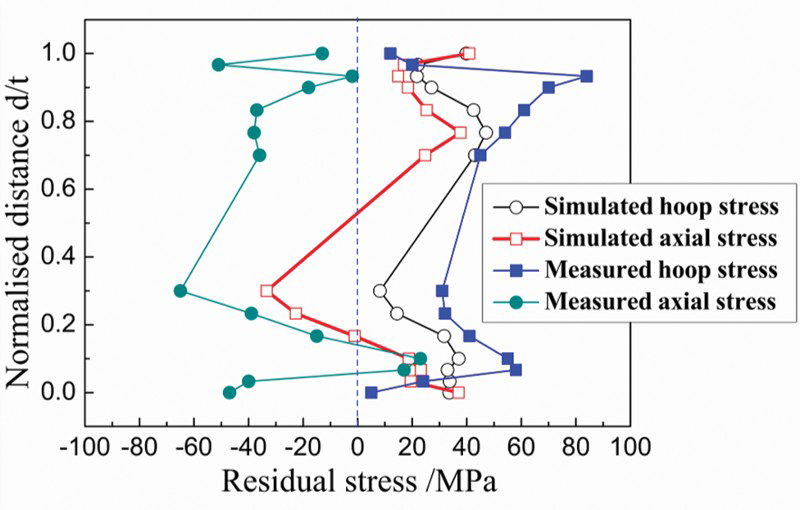
Through wall hoop stress and axial stress at the weld centreline after heat treatment
Evolution of through wall residual stress
To better understand the development of the through wall residual stress in multipass welding of large thickness rotor steel pipe, intermediate residual stress states after completing each weld pass are developed. Figure 9a and b shows these stress distributions for axial stress and hoop stress at the weld centreline respectively. Eight residual stress states are shown, each state corresponding to an intermediate state where a weld pass is complete.
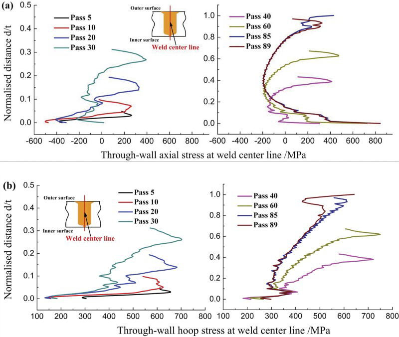
Evolution of through wall stresses at weld centreline: a axial stress; b hoop stress
The axial tensile stress appears toward the outer surface with a compressive stress region near the inner surface at pass 5 as shown in Fig. 9a. Thus, the distribution of through wall axial stress develops a bending type. This bending type distribution of through wall axial stress can be clearly identified at pass 30 (the weld height is ∼32% wall thickness from the inner surface) but maintains only several passes. A clearly self-equilibrating type of through wall axial stress at about pass 40 (the weld height is ∼43% wall thickness from the inner surface) is developed and maintains throughout the rest of the beads. In addition, the peak value of the axial compressive stress is almost unchanged (∼200 MPa) after pass 30, while the peak value of the axial tensile stress (∼840 MPa) is reached until the whole welding is complete.
From Fig. 9b, it can be seen that the hoop stress along the weld centreline varies from 130 to 750 MPa. The distribution pattern of hoop stress remains almost unchanged after pass 30. The axial and hoop stress distribution patterns of the first few passes at the weld centreline are apparently different from the final residual stress distribution as shown in Fig. 9a and b, which means that the first few weld passes have a significant influence on the distribution of the final residual stress. In addition, the stress distribution patterns for both axial stress and hoop stress remain almost unchanged after the weld seam grows to a certain height (∼32–43% wall thickness from the inner surface in this study). The similar conclusion is also drawn by Liu et al. 24 .
Evolution of residual stress on inner surface
Figure 10 shows the evolution of residual stress on the inner surface during welding. From Fig. 10a, the overall trend of hoop stress on the inner surface decreases gradually before pass 30, while the stress distribution remains unchanged after pass 30. The distribution pattern of hoop stress remains almost unchanged during the whole welding process. After the whole welding process, the residual stress increases gradually away from the weld centreline, and the calculated peak hoop tensile stress (∼390 MPa) appears at ∼15 mm away from the weld centreline. With further increasing distance from the centreline, the hoop stress decreases quickly and turns into compressive stress, and the peak value of hoop compressive stress is ∼150 MPa. It can also be seen from Fig. 10a that the peak hoop tensile stress during welding may be higher than 550 MPa, which is much larger than the peak value after welding. This high tensile stress during welding may lead to the production of weld cracks, which can reduce the service lifetime.
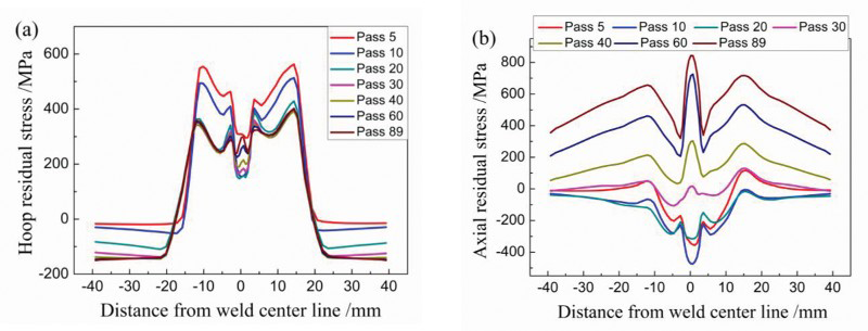
Evolution of residual stress on inner surface during welding: a hoop stress; b axial stress
As can be seen from Fig. 10b, the axial stress on the inner surface is almost always compressive stress before pass 40, while tensile axial stress is almost present on the inner surface after pass 40, and then the stress distribution of axial stress increases gradually with the growth of weld seam and the distribution pattern of axial stress maintains until the end of the last weld pass. Away from the weld centreline, the axial stress decreases sharply. At the fusion boundary, the axial stress reaches its lowest value in the weld zone, ∼360 MPa. The stress then increases rapidly and then a peak value (650 MPa) is reached at ∼12 mm away from the weld centreline. The highest tensile hoop stress is 850 MPa, which is much larger than the yield strength of the material at room temperature.
Evolution of residual stress at root bead
Figure 11 shows the evolution of the residual stress at point A of the root bead with subsequent weld beads deposited. As seen from Fig. 11, the axial stress is mostly compressive before pass 38 (the weld height is ∼43% wall thickness from the inner surface), except that a small amplitude hoop tensile stress is present at passes 2 and 3, and the peak value of the axial compressive stress is ∼510 MPa at pass 9. After pass 38, the axial stress is tensile and increases with the growth of the weld seam until the peak tensile stress is reached (∼654 MPa) at the last pass. The hoop residual stress after the first pass at point A is ∼608 MPa, which is the peak value of hoop stress at point A during the whole welding process. From Fig. 11, it can also be seen that the von Mises stress at point A varies from 164 to 598 MPa.
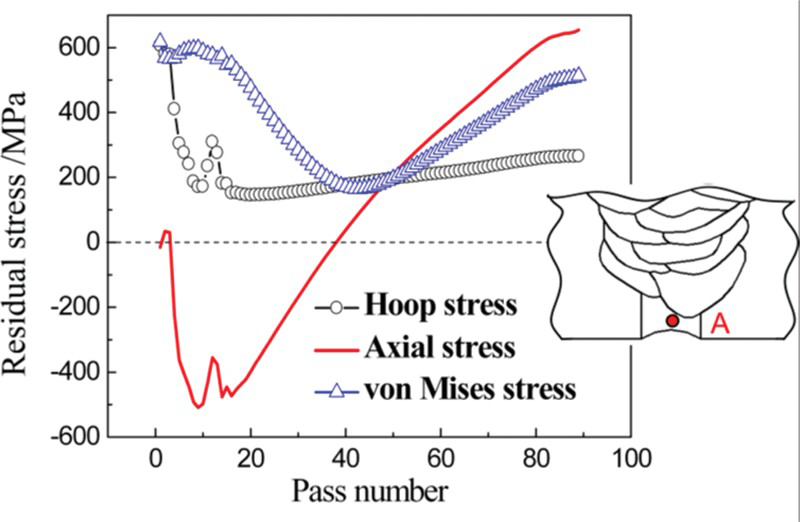
Evolution of stresses at point A
Conclusions
According to analysis results obtained in the present study, the main conclusions can be summarised as follows:
With the growth of the weld seam, the hoop stress always is tensile stress in the weld area, and two zones with hoop compressive stresses occur in the parent metal areas adjacent to weld seam. Before pass 30 deposited, the axial stress of outside surface of the pipe is tensile stress, and that of inside surface is compressive stress. While after pass 40, on the inside and outside surface of the thick walled pipe, large axial tensile stress can be observed, and a zone with compressive axial stress is generated in the internal of the pipe. A bending type distribution of through wall axial stress can be clearly identified before pass 30 but maintains only several passes. A clearly self-equilibrating type of through wall axial stress at about pass 40 is developed and maintains throughout the rest of the passes. The overall trend of hoop stress on the inner surface decreases gradually before pass 30 deposited, while the stress distribution remains almost unchanged after pass 30. The axial stress on the inner surface is almost always compressive stress before pass 40 deposited, while tensile axial stress is almost present on the inner surface after pass 40. The axial stress at root bead is mostly compressive before pass 38 (the weld height is ∼41% wall thickness from the inner surface), and then the axial stress turns into tensile stress after pass 38. Therefore, the distribution type transformation of the through wall axial residual stress occurs at pass 38.
Footnotes
Acknowledgements
The authors acknowledge the financial support of the National Science and Technology Support Program of China (grant no. 2009BAF44B00) and the China Doctoral Education Base Foundation (grant no. 20100201110065).