
Abstract
This paper presents procedures and technical parameters used for resource estimation of bauxite deposits including the non-consolidated pisolitic bauxite (Weipa) and the intensely lithified types (Gove, Sangaredi, Az Zabira). Bauxite resources are usually estimated by drilling and sampling drill holes at 0·25 to 0·5 m intervals. Short sampling intervals are necessary for accurate estimation of the mineralisation contacts; this is despite the broad drilling grid which varies from 125 m centres for definition of the measured resources to 500 m centres used for inferred resources. Samples of non-consolidated bauxite are often beneficiated by sieving and removing the barren fine grained material before chemical assays. Consolidated bauxite ores are not beneficiated and processed in a conventional manner. However, in both cases, the overall precision error (CV%) of the samples, which is measured and monitored using field duplicates, does not exceed 10% (Al2O3 – 5%; SiO2 – 10%, Fe2O3 – 7%, LOI – 10%). Bauxite density is preferably measured using the sand replacement method which is a formally certified technique for measuring bauxite density at the Australian deposits. However, a more recent approach is to use Sonic drilling to collect intact samples of the bauxite ore. Bauxite grade is estimated using conventional geostatistical techniques, most commonly by Ordinary Kriging. However, the method is applied after geometry of the bauxite seam is flattened using an equal thickness unfolding method, or, in some cases, using top flattening approach. Direct estimation of the bauxite grades without flattening their bodies produces incorrect estimates due to excessive smoothing of the estimated grades.
Introduction
Bauxite mining is generally carried out by large-scale open pit methods and requires beneficiation of the mined material. Operations typically produce 1–15 Mt of bauxite a year over a mine life of 20–40 years (Bardossy and Aleva, 1990). This paper summarises procedures used for bauxite resource estimation and describes the main sources of errors in various steps of estimation process. The approaches currently used for mitigating the risks of erroneous evaluations are explained with an emphasis on the best resource estimation practices.
The structure of this paper follows the main steps of the bauxite resource definition process: data collection, geological interpretation, mathematical (geostatistical) modelling and resource classification practices at bauxite deposits. Verification of the bauxite resources and their conversion to reserves are also briefly discussed.
Geology of the studied deposits
The data presented was collected during 2005–2013 at the mining operations and projects in Australia, Africa, South America, and the Middle East and include different types of bauxite ores varying from non-consolidated pisolitic mineralisation (Weipa) to intensely lithified bauxite beds (Gove, Sangaredi) and buried palaeo plateaus (Az Zabira; Fig. 1, Table 1).
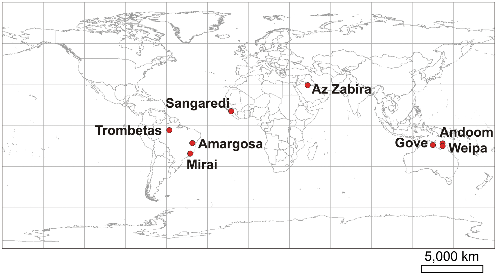
Location map of the studied bauxite deposits
Geological characteristics of the selected bauxite deposits
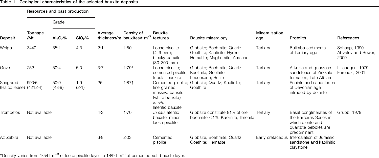
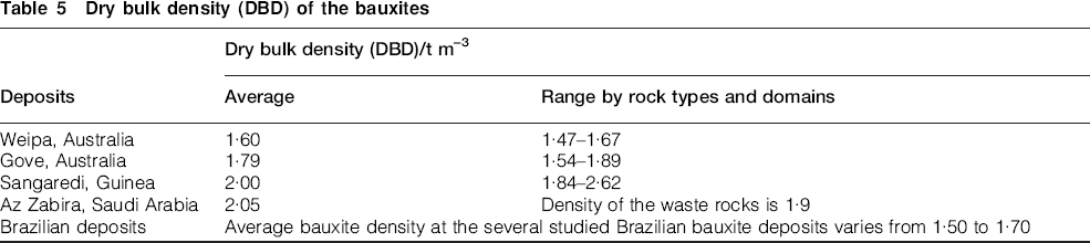
Density varies from 1·54 t m–3 of loose pisolite layer to 1·89 t m–3 of cemented soft bauxite layer.
1·87 t m–3 is used as average density for the bauxite located above 190 m RL. Residual basal bauxite has density of 2·00 t m–3.
Weipa
The Weipa deposit has been mined since the 1960s and is located on the west coast of the Cape York Peninsula (Fig. 2a). The bauxite ores are confined to a dissected laterite plateau which extends for approximately 180 km north-south (Schaap, 1990). The width of plateau varies from 20 to 60 km in an east-west direction (Fig. 2a).
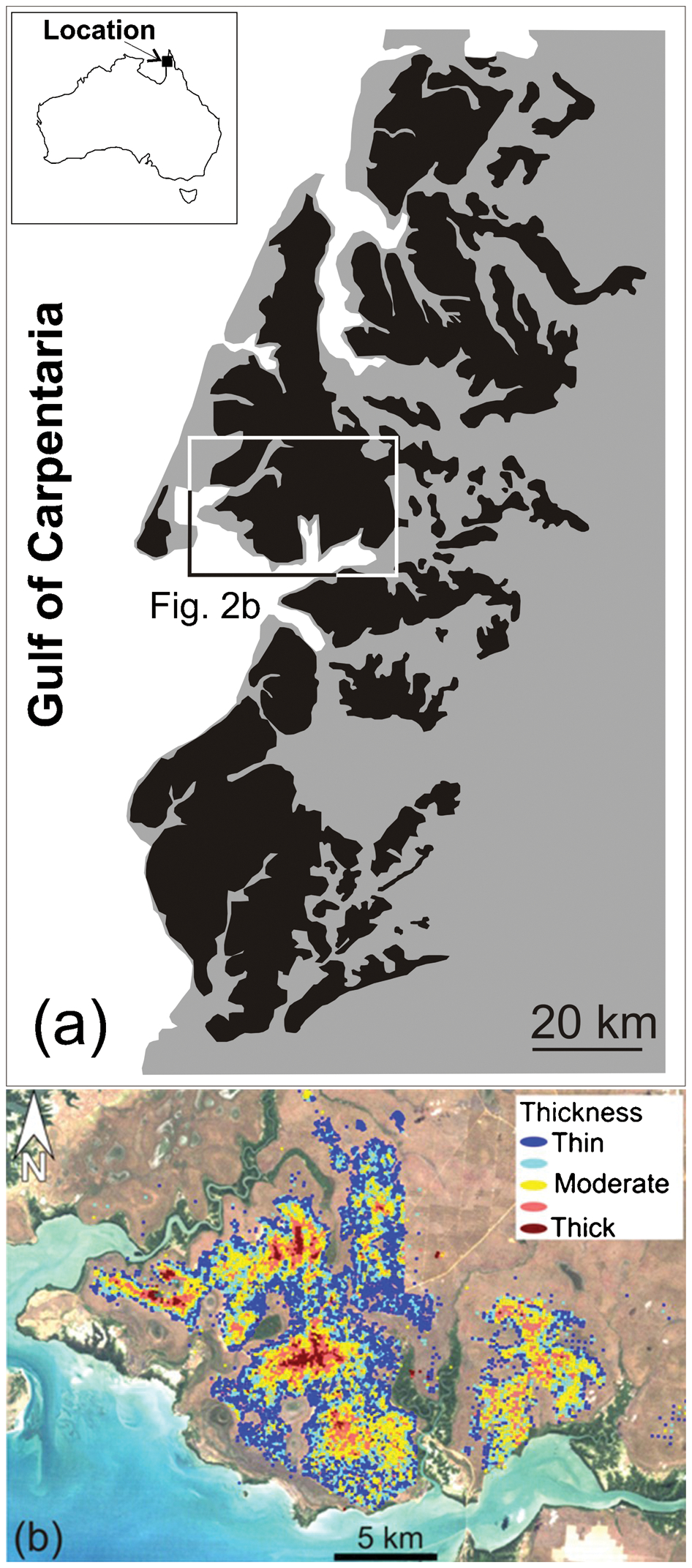
Weipa deposit: location of the map area is shown in Fig. 2a: a bauxite plateau (black) on the Cape York Peninsula; b distribution of bauxite thickness in the area of the Weipa deposit.
The plateau is composed of weathered material developed on the marine sediments of the Early Cretaceous Rolling Downs Group within the Mesozoic Carpentaria Basin (Schaap, 1990). The weathering profile is 20 to 35 m thick and includes a bauxite bed which is 0·0 to 20 m thick (Fig. 2b) and continues across the entire plateau. The bauxite is overlain by top soil which is on average 0·5 m thick and is underlain by an iron and silica-rich bed (ironstone) usually 1 to 2 m thick. The ironstone consists of goethite and hematite nodules with abundant quartz and kaolinite (Schaap, 1990; Abzalov and Bower, 2009). The contact between the bauxite bed and ironstone is uneven and can be gradational (Abzalov and Bower, 2009).
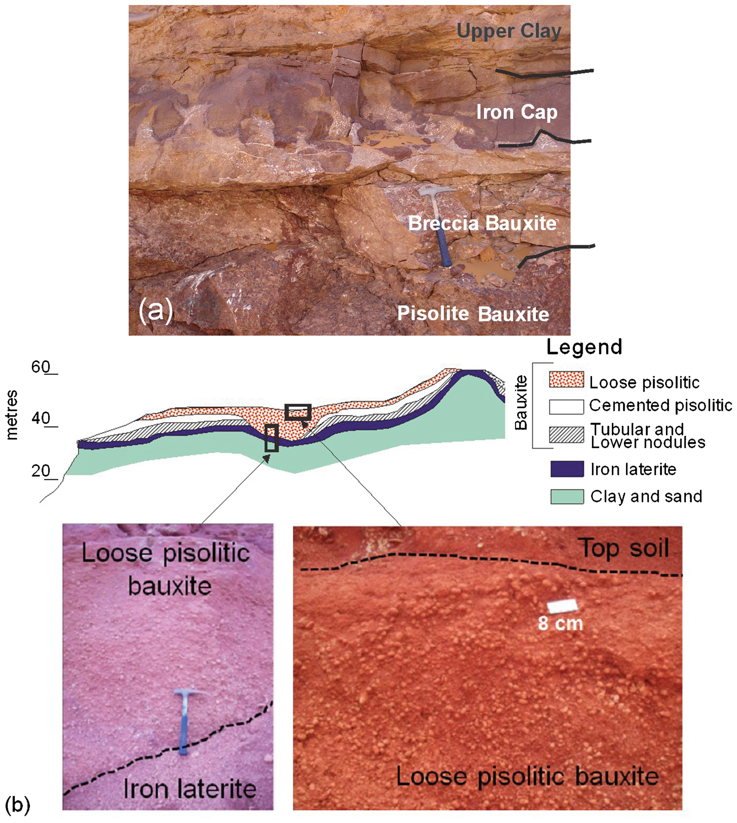
The same weathering profile is found throughout the entire Weipa plateau; however, the bed thicknesses vary widely (Fig. 2b). The degree of ironstone consolidation also changes, from strongly compacted duricrust to loose ironstone pisolites consisting of gibbsite and boehmite with minor kaolinite and quartz (Fig. 3a). In places, the bauxite is cemented forming a blocky mineralisation texture (Fig. 3b).
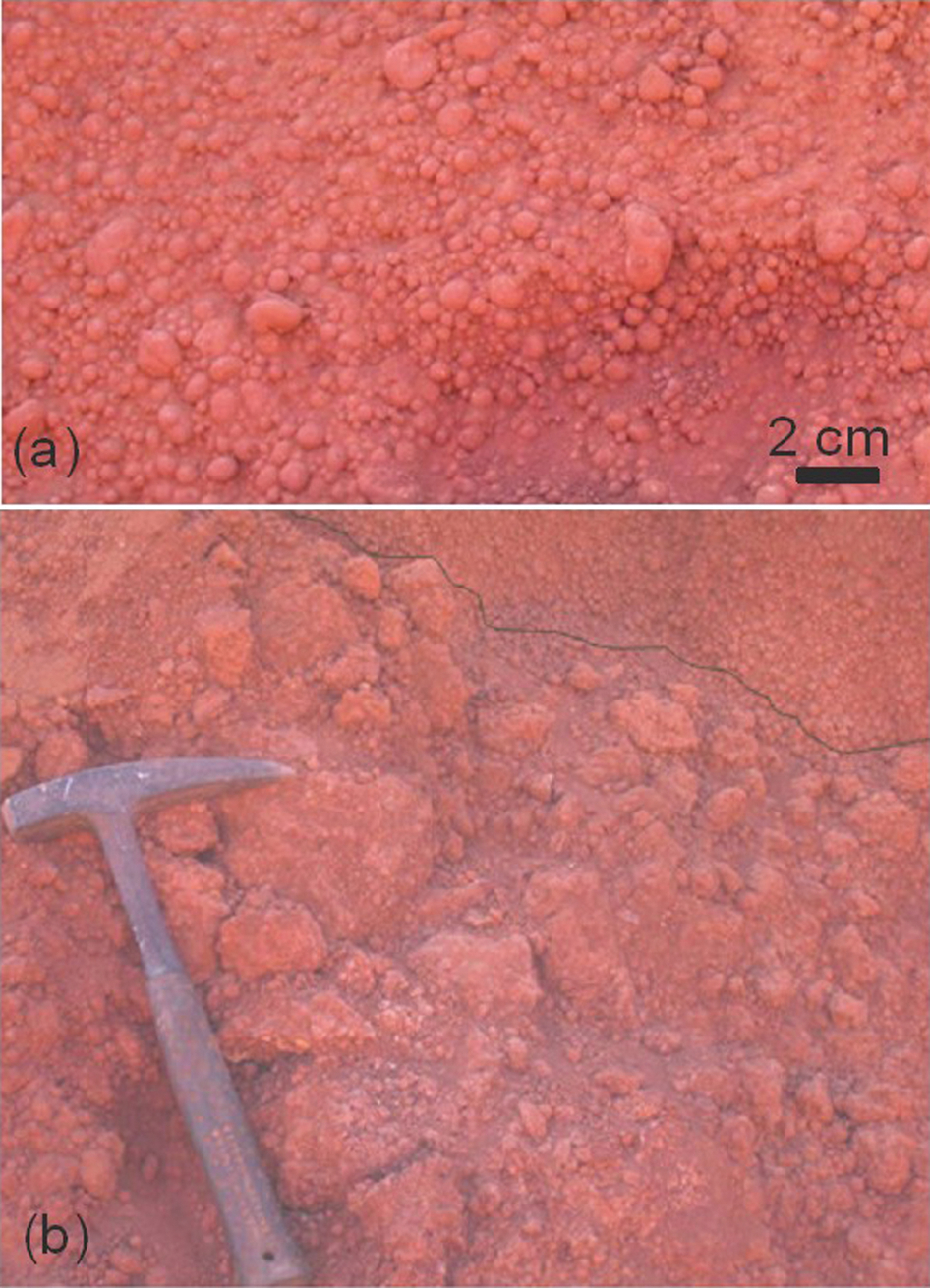
The main types of bauxite ore at the Weipa deposit: a loose pisolites; b blocky cemented bauxite.
The grade of the bauxite at the Weipa deposit varies from 45 to 55% Al2O3 and decreases towards both the upper and the lower contacts of the bauxite bed (Abzalov and Bower, 2009). Silica content varies from 0 to 20% SiO2, and gradually increases towards the bauxite contacts (Abzalov and Bower, 2009). Iron content varies in the range from 5 to 20% Fe2O3, usually increasing toward the contacts of the bauxite (Abzalov and Bower, 2009).
Gove
The Gove deposit is located on the Gove peninsula close to the coast of the Gulf of Carpentaria (Fig. 4a). It was explored during 1955 to 1968 and mined from 1971 at a rate of 6·5 Mt per year (Lillehagen, 1979; Ferenczi, 2001). Currently, the operation produces 10 Mt of bauxite per year.
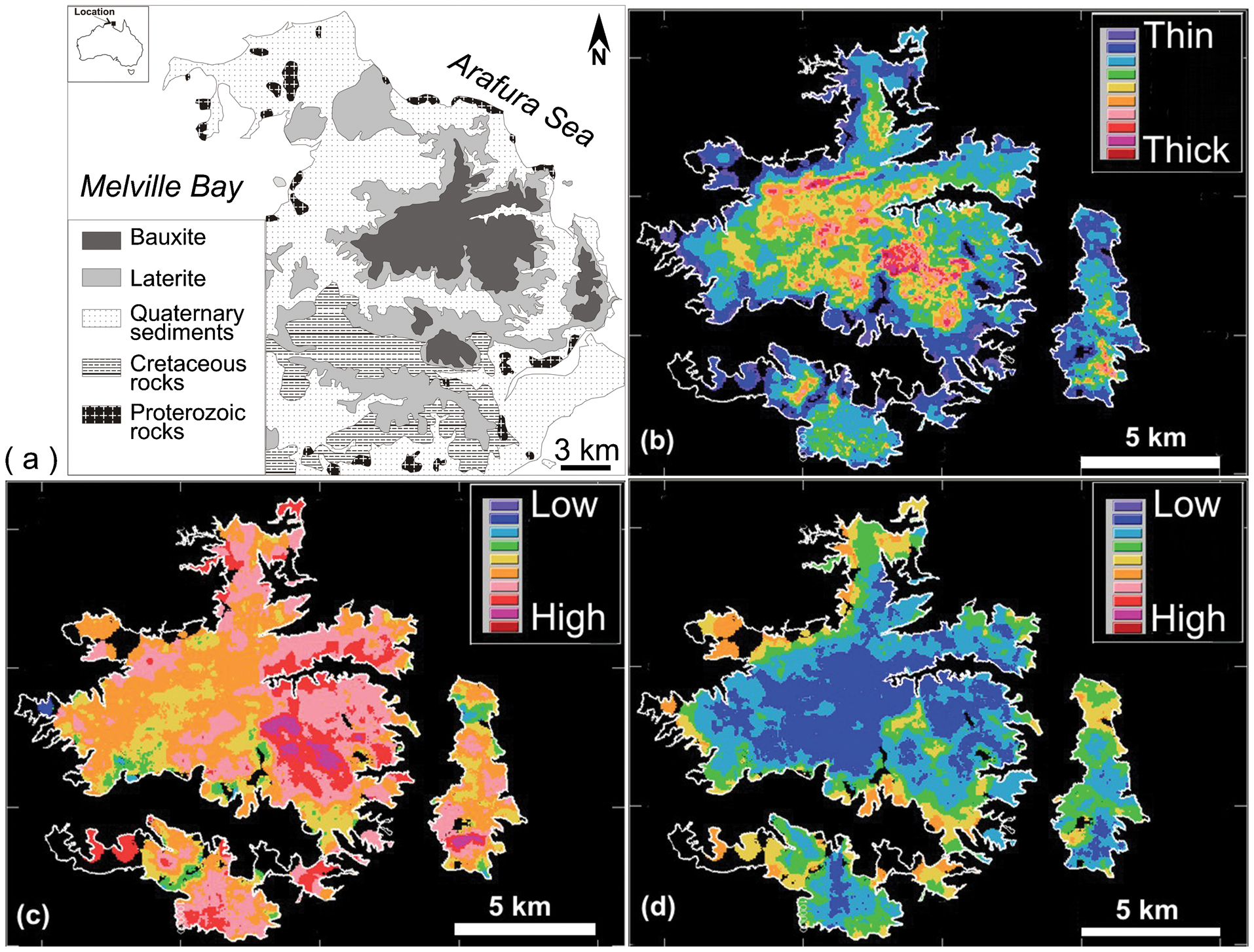
Gove deposit: a generalised geological map (after Ferenczi, 2001); b thickness of the bauxite seam; c Al2O3 grade of the bauxite seam; d SiO2 grade of the bauxite seam.
The bauxite ores are distributed on the plateau representing an eroded and dissected remnant of the Tertiary peneplain. The plateau is composed of a lateritic sequence developed on the sedimentary rocks of the Yirrkala Formation of Lower Cretaceous age, which, in turn, unconformably overlies the Proterozoic Bradshaw Complex (Fig. 4a). The Yirrkala Formation is 100 to 200 m thick, and composed mainly of sandstone interbedded with minor claystone (Ferenczi, 2001).
The bauxite seam is up to 10 m thick, with an average of 3·7 m. Thickness decreases towards the plateau margins (Fig. 4b). The alumina and silica grades also systematically change laterally across the deposit (Fig. 4c and d). Alumina grade is higher (Fig. 4c) at the plateau centre gradually decreasing towards the plateau margins. Silica content is higher at the plateau margins and decreases toward the centre (Fig. 4d).
At the Gove deposit, the bauxite is covered by a layer of the top soil of approximately 1 m thick, and underlain by a thin bed of nodular ironstone (Fig. 5a). The bauxite seam, in turn, is not uniform and is subdivided into four layers, each with distinct textures and chemical composition: loose pisolitic, cemented pisolitic, tubular and lower nodular (Fig. 5a). Characteristics of these layers are as follows:
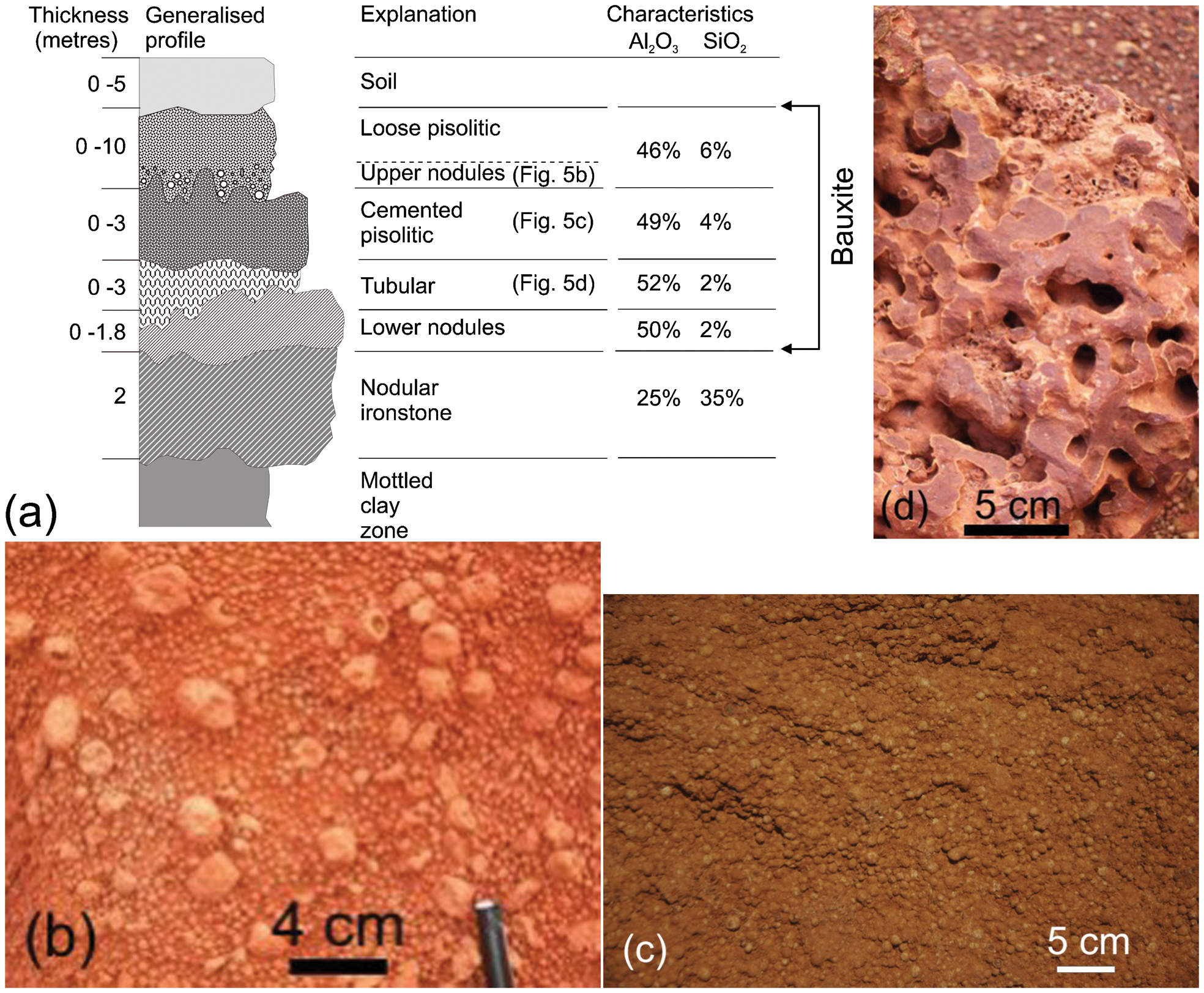
cemented pisolitic bauxite layer is similar to the loose pisolitic bauxite but differs by intensity of cementation (Fig. 5c)
tubular bauxite is massive and strongly cemented bauxite ore containing irregular anastomosing vesicular cavities which are lined with a creamy-yellow coating. The cavities are commonly infilled with complete or hollow pisoliths and, toward the top of this layer, contain cemented pisoliths. The cavities (tubes) are commonly vertical (Fig. 5d)
lower nodular bauxite is located at the bottom of the bauxite seam. This is the most discontinuous and thinnest layer, which is on average 0·3 m thick. It consists of very loosely cemented nodules that range in size from 5 to 30 mm. Lower nodules are usually solid.
These layers are discontinuous and characterised by highly variable thicknesses. In particular, loose pisolitic bauxite locally can form up to 10 m thick lenses filling erosional channels and depressions cut through the entire bauxite sequence. Contacts between layers are sharp, however the shape of the contact surfaces is highly irregular (Fig. 5a).
Tubular bauxite is consistently higher in alumina and lower in silica then loose pisolitic and cemented pisolitic bauxite. The grade of the lower nodular bauxite is similar to the tubular bauxite.
Sangaredi
Bauxite was discovered in Guinea at the beginning of the twentieth century and systematically explored after World War II, resulting in the discovery of Sangaredi, the largest bauxite deposit in the world (Fig. 6).
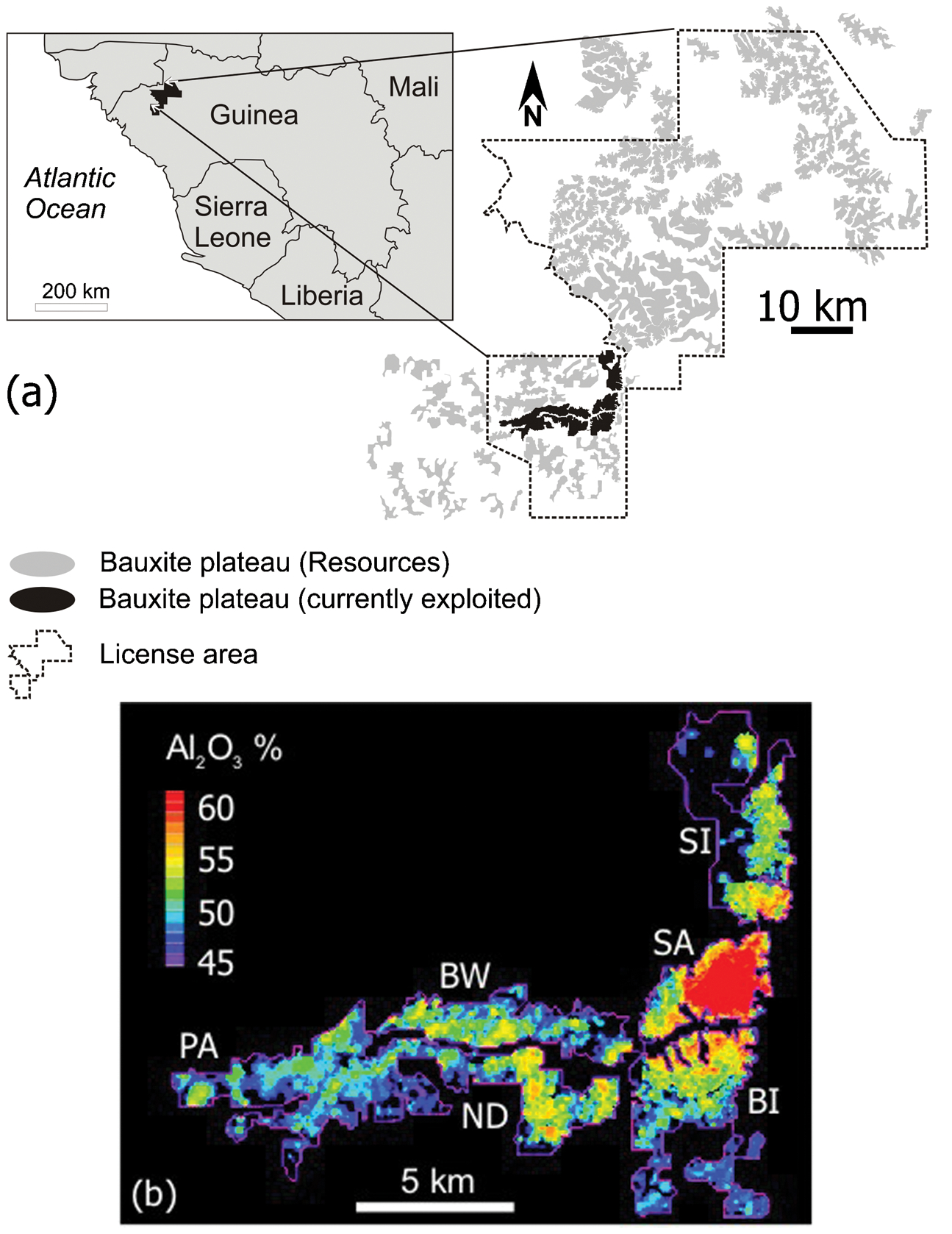
Sangaredi deposit: PA – Paravi, BW – Boundou Waade, ND – N'Dangara, BI – Bidikoum, SA – Sangaredi, SI – Silidara: a distribution of the main bauxite plateaus in the central Guinean bauxite belt; b distribution of Al2O3 grade at the currently exploited plateaus (shown as black on Fig. 6a)
Production from the Sangaredi plateau commenced in 1973, at the rate of 9 Mt per year. At present, bauxite is produced from six plateaus: Sangaredi, Bidikoum, Silidara, N'Dangara, Boundoum Waade and Paravi (Fig. 6), with total annual production exceeding 15 Mt.
The bauxite seam on the Sangaredi plateau is on average 20 m thick. It lies over Devonian schist and sandstone intruded by Mesozoic dolerite. In the more recently explored bauxite plateaus situated farther to the north of the currently mined plateaus (Fig. 6), the geology is similar except that weathered dolerite appears to be the main source of the bauxite. The bauxite here is between 2 to 12 m.
Despite local heterogeneity, the bauxite profile is distinctly zoned, which is consistent across the entire belt. The upper portion is usually iron-rich and distributed as a solid crust 1 to 2 m thick covering the massive bauxite. The massive bauxite layer is on average 3 m thick and yields the highest alumina grades. Beneath this there is a 5 m gravelly bauxite layer containing oolitic bauxite with pebbles of concentric concretionary structure. Oolites are distributed mainly in the lower part of the layer where alumina content decreases and iron and silica contents increase.
Az Zabira
The Az Zabira deposit is located in a remote part of northeastern Saudi Arabia, approximately 460 km from the Persian Gulf (Fig. 1). It represents a palaeo-laterite profile formed in the Early Cretaceous time on the Jurassic claystone and sandstone. This laterite marks a major regional Early Cretaceous unconformity which is overlain by sediments of the Wasia and Aruma formations. The Wasia Formation is Early to Late Cretaceous age and is composed of sandstone and conglomerate intercalated with claystone and minor chert. The Aruma Formation of Late Cretaceous age is mostly composed of limestone.
The bauxite seam has a strike length of 105 km and gently dipping to the east-northeast (Fig. 7). It partially crops out along a cuesta scarp within three main mineral zones, named according to their geographic positions as South, Central and North Zones (Fig. 7). Bauxite of the Az Zabira deposit has been cemented and underwent intense secondary silicification. As a result the bauxite seam is a hard competent rock characterised by high silica content (Table 1).
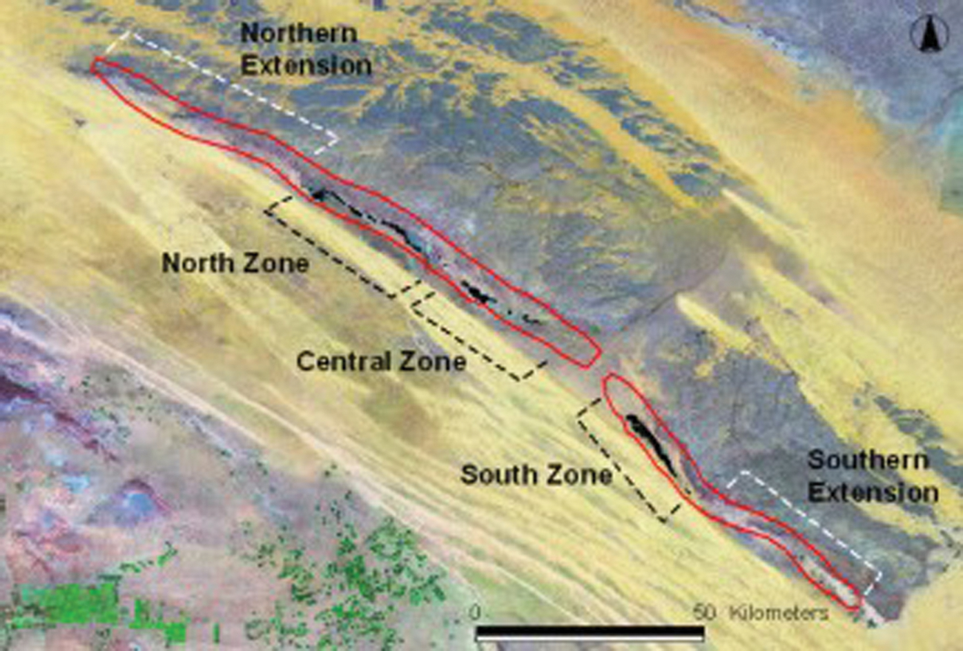
Landsat TM imagery (RGB 742) of the Az Zabira bauxite deposit. Red outline denotes extents of the bauxite seams presented in the DGRM, 1994. Black fields – bauxite outcrops digitised from the 1∶50 000 scale map. Northern and Southern Extensions represent the areas where bauxite seam is entirely concealed under younger sedimentary rocks
Brazilian deposits
Several Brazilian deposits have been reviewed in the current study (Fig. 1). The best studied is Trombetos, located in the Lower Amazon basin (Fig. 8a). Geological characteristics of the deposits in the basin were comprehensively described by Grubb (1979) and therefore only summarised in this section.
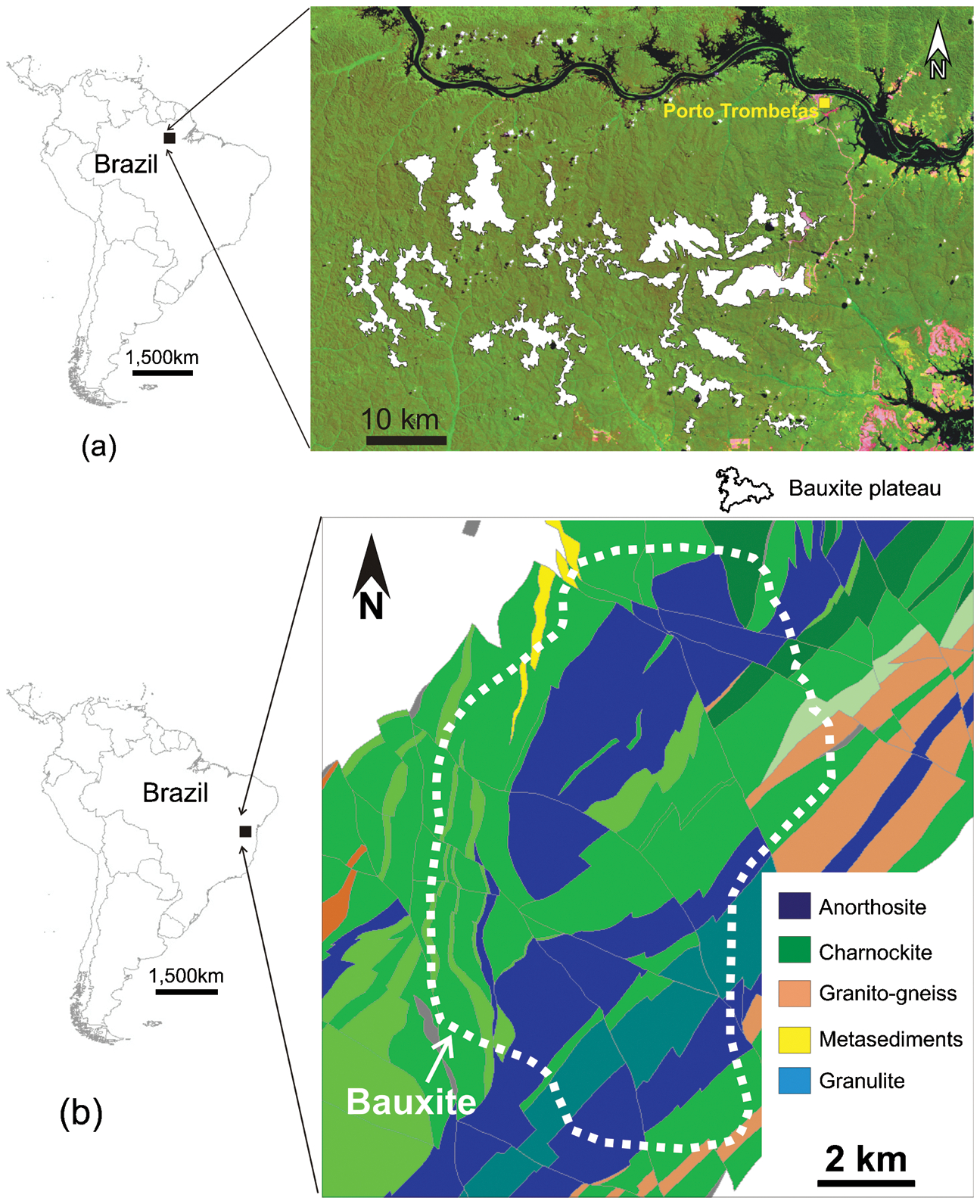
a location map of the bauxite plateaus at the Trombetos deposit and b bed rocks geology at the Amargosa deposit
The main bauxite horizons in the Lower Amazon basin are confined to the Tertiary – Quaternary stratigraphic interval and restricted to highly dissected 70 to 120 m high plateaus which have steep 30° flank profiles. Bauxite is covered by Belterra Series clay which increases in thickness from margins toward the plateau centres.
The essential feature of the Trombetos deposit is the presence of an upper pisolitic or nodular bauxite horizon successively underlain by a massive bauxite hardcap and a concretionary earthy bauxite and by a dark reddish mottled clay (Grubb, 1979). These layers are spatially discontinuous and the bauxite footwall contact is usually irregular. A specific feature of the deposit at Trombetos is the pockets of porous cellular bauxite with coarse stalactitic concretions. The deposit is also characterised by the presence of the ferruginous quartz-rich laterite horizon directly above the massive bauxite hardcap.
The Amargosa deposit is located in central Brazil, approximately 100 km from the Atlantic coast (Fig. 8b). A thick layer of in situ lateritic bauxite was formed during the Tertiary epoch over Precambrian gneiss, charnockite, metasedimentary rock and anorthosite (Fig. 8b). It is composed of earthy, massive and nodular bauxite intercalated with beds of clay.
The thickness, composition and quality of the bauxite vary depending on the type of source rock. The bauxite overlying anorthosite is thicker and also of a better quality than those derived from charnockite and gneiss. These strong compositional differences of the Amargosa bauxite is a basis for subdividing the deposit into high and low grade domains for their separate modelling and resource estimation. The deposit is also characterised by irregular distribution of alumina and silica in the bauxite profile which is complicated by presence of saprolite and clay lenses in the bauxite sequence.
Drilling
Drilling type
Bauxite deposits are usually large and can cover areas of several hundred to several thousand square kilometres (Figs. 2 and 6) and therefore the estimation of bauxite resources requires thousands of drill holes (Table 2). The total drilling varies from several thousand metres, to several hundred thousand metres (Table 2).
Resource estimation data at the selected bauxite deposits
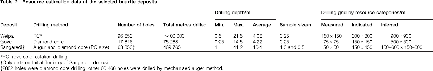
RC, reverse circulation drilling.
Only data on Initial Territory of Sangaredi deposit.
2882 holes were diamond core drilling, other 60 468 holes were drilled by mechanised auger method.
Due to high drilling costs, it is preferable to use cheaper drilling methods such as RC and auger (Table 2). Diamond drilling, which is more expensive, is used only when other drilling methods may be suboptimal for accurate categorisation of the bauxite types and estimation of their resources.
Auger drilling, which is the main drilling method at the Sangaredi deposits (Table 2), tends to overestimate the thickness of the bauxite seam because of downhole sample contamination. Therefore, when using auger drilling the results need to be verified and if necessary corrected using diamond drilling. Alternatively, sonic drilling can be used for the verification of auger drill results. Sonic drilling is routinely used for estimating the resources of mineral sands (Abzalov et al., 2011) and has recently been applied for the verification of bauxite resources.
Drilling grids
There are various drilling grids suitable for the definition of bauxite resources (Table 2). The differences in the drilling grids chosen for defining resource categories reflect differences of the deposit complexities. In particular, this is the difference in spatial variability of deleterious components and the uncertainty of the footwall contact topography or the presence of internal waste (Abzalov and Bower, 2009). Based on the studied deposits (Table 2) the following guideline drill grids can be used for planning:
measured resource: average 125×125 m (range from 50×50 to 200×200 m)
indicated resource: average 250×250 m (range from 100×100 to 400×400 m)
inferred resource: average 500×500 m (range from 200×200 to 900×900 m).
Some operations drill additional holes at the production stage infilling their resource definition drill grids. In particular, at the Sangaredi mine, probable reserves are developed by infilling the 150×150 m drill grid used for indicated resources to 75×75 m. Proved reserves are defined by infilling the grid to 37·5×37·5 m.
Sampling and logging holes
It is common practice to sample resource definition holes at short intervals, usually at 0·25 or 0·5 m (Table 2). Small samples are needed for the accurate definition of the footwall contact to prevent dilution of the bauxite by footwall material, which is usually characterised by high content of the deleterious components, in particular silica and iron (Fig. 5). They are also necessary for construction of the accurate reserves models of the bauxite deposits which are commonly mined selectivity at 0·5 m benches.
Logging of the drill hole samples includes a description of the bauxite types including loose pisolitic, cemented pisolitic, tubular, nodular, blocky bauxite and earthy bauxite. It is also a common practice to document the type and distribution of the iron oxides and hydroxides present as impurities in the bauxite, e.g. ironstone pisolites or fine grained earthy material where goethite and limonite are mixed with clay minerals. The latter is reflected in the bauxite colour, which is classified using a standard palette.
Silica, iron and titanium minerals need to be identified and recorded in all geological logs. Silica is commonly presented as quartz (SiO2) and hydrated aluminium silicate clays (e.g. kaolinite – Al2O3*2SiO2*2H2O and halloysite – Al2O3*2SiO2*3H2O). Titanium usually is present as ilmenite (FeTiO3), rutile (TiO2) and anatase (TiO2). These minerals and iron oxides are typical for bauxite ores developed on anorthosites.
Geotechnical characterisation of bauxite includes the following standard parameters: rock density, hardness and moisture. At some Brazilian operations it also includes documentation of plants and rock boulders intersected by the drill holes. They can be serious obstacles for the transportation of bauxite by conveyor belts and can also cause a disruption of the bauxite beneficiation at a metallurgical plant.
Sample preparation and assaying
Sample preparation
The different types of the sample preparation are used for non-cemented and cemented bauxites. Non-cemented bauxite is upgraded (beneficiated) by sieving and washing away the fine fraction which mostly contains clay and silica rich minerals. The sieve fraction is determined empirically and can be different at different deposits or at the different parts of the same deposit depending on their grade vs size fraction profile. Examples of the sieve size used for beneficiation of the bauxites are as follows:
Deposit 1: −10 mesh (−1·7 mm) discarded, +10 mesh (+1·7 mm) is retained
Deposit 2: −28 mesh (−0·6 mm) discarded, +28 mesh (+0·6 mm) is retained
Deposit 3: −48 mesh (−0·3 mm) discarded, +48 mesh (+0·3 mm) is retained.
Beneficiation is measured as the ratio of the weights of the recovered (beneficiated) bauxite to the weight of sample before processing. This ratio is referred to as the ‘yield’ and expressed as a percentage. Beneficiated bauxites are dried and then ground and pulverised, usually to 200 mesh (0·074 mm) for analysis using inductively coupled plasma mass spectrometry and X-ray fluorescence (XRF) methods. An example of a sample preparation protocol is shown in Table 3.
Example of the sample preparation and quality control protocol
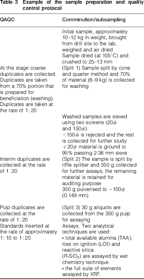
Cemented bauxite is not beneficiated but samples are processed in a conventional manner by drying the sample followed by crushing, grinding and pulverisation. Sample preparation protocols are commonly optimised by estimating the Fundamental Sampling Error and constructing sampling nomograms according to the Theory of Sampling (Gy, 1979).
Analytical techniques
When processing includes beneficiation of bauxite, the weight of rejected and retained material is reported for all samples. The retained samples are assayed for Al2O3 and all deleterious components, in particular SiO2, TiO2, Fe2O3, Mn, Zn, Ca and P2O5. These components are usually assayed by conventional XRF. However, special analytical techniques are often used in order to more accurately determine metallurgical characteristics of the bauxite. In particular, when silica is present in different minerals additional assays are made for the accurate estimation of concentration of reactive silica which can be a serious hazard for alumina production from bauxite by the Bayer process. Loss on ignition (LOI) should be recorded for all assayed samples. This is an important check of the assay quality as the sum of the oxide weights and LOI should be close to 100 wt-%. It is also needed for recalculating the chemical composition of samples to their mineralogical composition using stoichiometric mineral formulas. This is used at some operations (e.g. Weipa) for the mineralogical classification of bauxite products. In addition to the oxides and LOI measurements, the following are determined on a project basis:
quartz: the percentage of quartz in a sample is determined through a wet chemical technique, whereby a strong acid dissolves the silica. This process is both costly and time consuming and poses significant health and safety risks to the laboratory analyst. Other methods are currently being evaluated for this determination:
kaolinite: the amount of kaolinite in a sample, is calculated as the difference between assayed SiO2 content and the amount of quartz
organic carbon: this variable is used in orebody models. Organic carbon is measured using a commercial carbon analyser which is both proven and simple
alumina species: tri-hydrate (THA) and monohydrate (MHA). These are traditionally determined through a bomb digest. This process replicates the conditions in the digestion train in an alumina refinery and allows the concentration of both high temperature digestible alumina (MHA) and low temperature digestible alumina (THA) to be determined.
Sample quality control (QAQC)
Sample quality control at bauxite projects is similar to conventional QAQC procedures in the mining industry (Abzalov, 2008). The frequency of collecting duplicate samples at the bauxite projects is usually 1∶10 to 1∶20 (Table 3). The duplicates are used for estimating sample precision which is reported as CV% (Abzalov, 2008). The different types and generations of data can significantly vary in quality. In particular, the main challenge in assaying bauxite ores is ensuring a good repeatability of the yield (beneficiation) values.
Some examples of precision errors at two bauxite projects are shown in Table 4. These can be used as a guideline on the acceptable precision of samples collected for the estimation of bauxite resources. Standard samples are used to check the laboratory analytical accuracy and inserted at rates of 1∶20, similar to other types of metallic deposits (Abzalov, 2008).
Precision error (CV%) estimated using duplicate samples
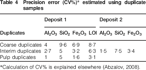
Calculation of CV% is explained elsewhere (Abzalov, 2008).
It is noted that QAQC procedures at the bauxite deposits have specific features caused by drilling and sampling of soft, non-consolidated sediments including:
recovery of drill hole samples is usually limited to measuring their weights which is often insufficient for assuring sample quality and representativity
using blanks is impractical for controlling sample contamination in the laboratory.
The above mentioned difficulties are partially overcome by drilling twin holes which are commonly used at bauxite projects as a routine method of data quality control, and for verification of historic data (Abzalov, 2009).
Dry bulk density (DBD) of the rocks
The techniques used for measuring the dry bulk density (DBD) of bauxite are:
sand replacement method (Weipa, Gove)
diamond core drilling (Gove, Sangaredi)
PVC tube (Trombetos)
sonic drilling (Amargosa).
The sand replacement method is a common method which is formally certified for measuring bauxite DBD at the Australian deposits (Abzalov, 2013a). Unfortunately it is impractical when the thickness of the bauxite seam reaches several metres. In this case application of the sand replacement technique will require digging of exploration pits therefore a modern practice is to use sonic drilling to collect intact samples for accurate DBD measurement (Abzalov et al., 2011).
Assigning rock density values to a block model is usually made by calculating average DBD values for each domain and the material types which are constrained by a geological model (Table 5). A single value is assigned to the entire volume occupied by the corresponding type of material. Interpolation of the DBD data using geostatistical algorithms, as practised with base metal deposits (Abzalov, 2013a), is usually inapplicable at the bauxite deposits due to insufficient DBD data.
Dry bulk density (DBD) of the bauxites
Some sites such as Sangaredi deduce DBD values for each modelled block from their chemical compositions. Although methodologically such approach is appropriate, it requires thorough calibration of relationships between density and chemical composition of the bauxite ores. The calibration should be regularly repeated and confirmed in particular if any new material type is encountered.
Geological constraints of the resource models
Geometry of mineralisation
Accurate estimation of bauxite tonnage is a challenging task because of the irregular geometry of mineralisation. In particular bauxite plateaus are strongly dissected by erosional troughs and creeks making the plateau edges extremely irregular (Figs. 4 and 6). Delineation of the boundaries of such plateaus by drilling is inefficient and is excessively time consuming, expensive and inaccurate. An alternative approach commonly used in the past was based on the interpretation of satellite images. The modern practice is to delineate plateau edges using airborne surveying techniques which are more accurate than satellite images. The technology includes airborne radar survey or airborne laser survey. The radar survey used at the Trombetos deposit in Brazil has a resolution of 2·5 m per pixel which produces accurate edges of the bauxite plateaus. This technique also simultaneously generates the digital model of surface, even in the presence of dense vegetation because the wave length can be adjusted to ensure that signals are penetrate to ground.
At the Gove deposit the plateau edges are currently delineated by airborne laser survey which also produces noticeable improvement in the interpreted geometry of the bauxite ore bodies.
Contacts
Bauxite seam contacts are usually sharp but can be highly irregular (Fig. 9). Special geostatistical studies undertaken at the Weipa and Andoom deposits have shown that the geometry of the footwall contact is characterised by a large uncertainty exceeding the effects of the bauxite alumina grade, content of the deleterious components, and thickness of mineralisation (Abzalov and Bower, 2009).
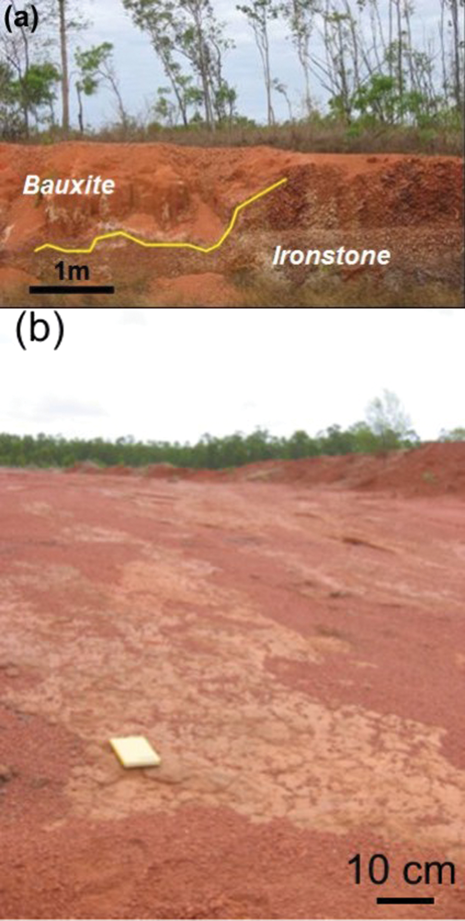
Examples of the bauxite contacts: a irregular footwall contact of the bauxite at the Andoom deposit; b flat and continuous footwall contact of the pisolitic bauxite with indurated ironstone at the Weipa deposit.
The procedure of constraining the bauxite seams are as follows. First, it is necessary to study the vertical profiles of the laterite sequence with an emphasis on changes of the chemistry through the bauxite contacts. Where contacts are sharp, the bauxite grade is modelled and estimated using a hard-boundary approach, without diluting the mineralised samples by the low-grade samples located outside of the contacts.
Sharp contacts are characterised by a rapid change in chemistry between the bauxite and their host strata (Fig. 10a). This is the most common type of bauxite contacts at most of the studied deposits (Fig. 10b and c). Alternatively, when contacts are gradational, the laterite changes gradually produce a gentle slope of the curve on the diagram depicting the average composition of the drill hole samples (Fig. 10a). Such contacts are less common at the studied bauxite deposits. When they are encountered, the grade of the bauxite ores is modelled and estimated using a soft-boundary approach.
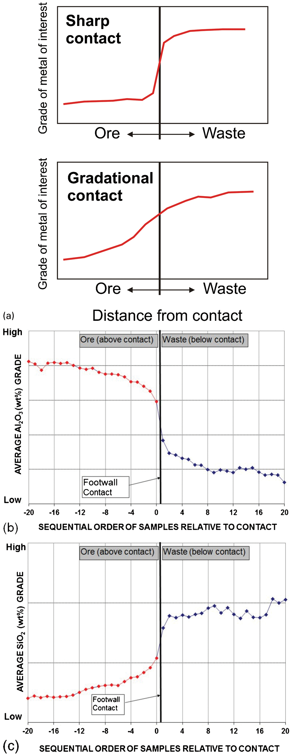
Changes in the laterite chemistry through the footwall contact of the bauxite seam: a sketch explaining the principles of diagnostics of sharp or gradational contacts; b distribution of Al2O3; c SiO2 through the footwall contact of the bauxite deposit, average of 350 holes.
Second, contact surfaces are delineated, either geostatistically or by manually digitising them on cross sections. A geostatistical approach is faster and produces more accurate models (Goovaerts, 1997; Chiles and Delfiner, 1999). It is particularly beneficial in hilly terrains (e.g. Amargosa) where manual digitising will be excessively time consuming and require a large density of cross sections. Based on personal experience the authors suggest delineating bauxite contacts using Ordinary Co-Kriging. For the upper contact the drill hole piercing points are used as a target (i.e. main) variable. The auxiliary variable is a topographic surface derived from the digital surface model. The footwall contact is modelled by Ordinary Co-Kriging using bauxite thickness as a target variable and the upper contact as an auxiliary variable (Goovaerts, 1997; Chiles and Delfiner, 1999).
The same approach can be used where a bauxite seam includes several different units which need to be modelled separately. However, it is important not to over complicate the geological model because this increases resource model uncertainty and risks of estimation errors.
Structure of the bauxite seams
Bauxite seams are rarely uniform and often exhibit strong vertical (Fig. 5) and horizontal zoning (Figs. 2b and 4), which complicates the estimation of their resources. Two of the most common types of the vertical bauxite seam profiles are shown in Fig. 11.
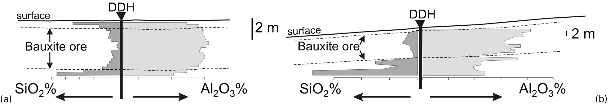
Distribution of the SiO2 and Al2O3 along the vertical profiles of the bauxite seams: a gradational zoning of the bauxites at the Weipa deposit; b intercalation of high and low grade bauxites and clay lenses at the Sangaredi deposit.
Gradational zoning is characterised by a gradual decrease in Al2O3 and an increase in SiO2 towards the upper and lower contacts of the bauxite seam (Fig. 11a). This type of zoning is best expressed at the deposits of the Weipa plateau. Definition of ore grade and classification of the bauxite products depends on their overall chemistry, therefore resource models of the bauxite deposits need to accurately reproduce the vertical profiles of Al2O3 and SiO2. This is usually achieved by applying a special unfolding algorithm, referred to as the equal thickness unfolding method. This algorithm flattens geological strata and equalises its thickness by changing the vertical coordinates of the drillhole samples, hence normalising the thickness. The same transformation is made to the block model.
Another type of zoning is represented by irregular intercalation of the different types of sediments, including high grade and low grade bauxite and barren rock, which are usually lenses of clay or discontinuous beds of shales (Fig. 11b). It is also modelled using the equal thickness unfolding method or, alternatively, it can be modelled using a top flattening method. The latter is particularly efficient when the bauxite seam contains erosional channels which make equal thickness unfolding unsuitable for accurate representation of the bauxite structure. Further improvement can be achieved by applying Plurigaussian simulation (PGS) algorithms (Armstrong et al., 2011).
Deposits which have experienced several episodes of weathering and diagenetic reworking (e.g Gove, Az Zabira) have a stratified structure formed by the stratigraphic succession of the different bauxite layers (Figs. 5 and 12). Separating layers for their independent modelling is inefficient for resource estimation. The layers are discontinuous and characterised by rapid thickness changes over short distances and have highly irregular contact geometries (Figs. 5a and 12a). An additional challenge is to represent the presence of erosional channels cutting the entire bauxite profile (Fig. 12b) and the gradational zoning observed within some layers. Personal experience of the authors suggests that the best results are obtained when such deposits are modelled using the PGS method (Armstrong et al., 2011).
Layered bauxite seams: schematic cross-section is from Lillehagen (1979): a stratified distribution of the different bauxite types, iron laterite and upper clay zone at the Az Zabira deposit; b discontinuous bauxite layers and erosional channels at the Gove deposit.
Domains
Estimation of mineral resource requires subdividing mineralisation into geostatistically uniform parts, referred to as stationary domains (Goovaerts, 1997; Chiles and Delfiner, 1999). However, the bauxite plateaus are usually zoned laterally (Figs. 2b, 4 and 6b). Thickness of mineralisation is larger and Al2O3 grade higher in their central parts gradually decreasing toward the plateau margins (Figs. 2b, 4b and 4c) accompanied by a reverse change in SiO2 content (Fig. 4d). The same zoned pattern can be repeated in different plateaus, e.g. Gove deposit (Fig. 4). Conversely, a single zoning can be observed across the entire belt or the part of the belt, encompassing several plateaus, e.g. Sangaredi deposit (Fig. 6b).
The strongly zoned structure of bauxite deposits means that defining geostatistically stationary domains is a particularly challenging task. A common approach is to define each zoned plateau as a separate domain and model them independently (e.g. Gove). Alternatively, a group of plateaus can be modelled as a single domain if the grade continues across the plateau margins. In the more complicated cases, when the spatial distribution of the estimated variables exhibit a strong non-stationarity, accurate estimation of the bauxite resources may require the application of non-stationary geostatistical techniques, such as Universal Kriging or Kriging with External Drift (Goovaerts, 1997; Chiles and Delfiner, 1999).
There are also cases when a single plateau is subdivided into several domains which are modelled separately. In particular, bauxite formed on anorthosite is commonly modelled separately from the bauxite developed on charnokite and gneiss in order to prevent excessive smoothing of the high grade of the anorthositic bauxite.
Estimation bauxite grade
Data preparation
Bauxite resources are commonly estimated using small samples, usually 0·25 m (e.g. Weipa) or 0·5 m (Sangaredi, Az Zabira). This is necessary for accurate modelling of heterogeneous bauxite seams. High grade cut offs are not applied, although some of the variables can demonstrate highly skewed statistical distributions.
Block model parameters
Vertical dimensions of the parent cells match the sample size (0·25 and 0·5 m). Lateral dimension of the parent cells is approximately half the distances between drill holes (Table 2).
Estimation methods
Ordinary kriging is the main estimation method applied at these bauxite deposits. It is supported by conditional simulation, usually using Sequential Gaussian Simulation algorithm applied to the bauxite grade and thickness for quantification of the resource model uncertainties and risks (Abzalov and Bower, 2009). Improvement of the geological model of the stratified bauxite strata can be achieved by applying the PGS method (Armstrong et al., 2011) which is currently investigated at the selected deposits.
Variography
Construction and modelling of the variograms is usually made after the mineralisation geometry is simplified using unfolding algorithms. In the unfolded environments most of the studied variables produce robust 3D variograms (Fig. 13; Table 6).
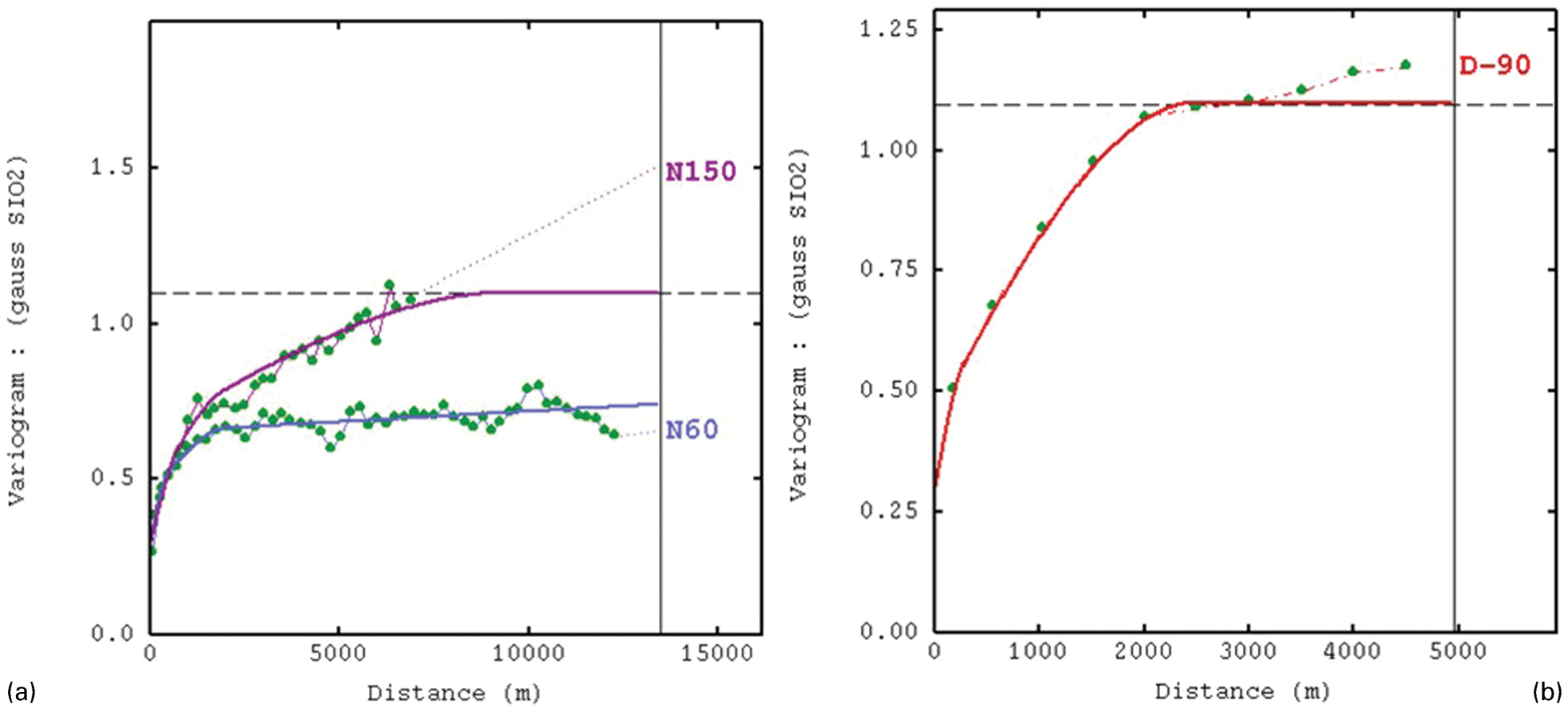
Experimental variograms and models of the Gaussian transformed SiO2 values estimated at the Weipa plateau: a horizontal variograms calculated along strike (N60) and dip (N150) directions; b vertical down (D-90) variogram.
Example of the alumina and silica variogram models from several bauxite deposits
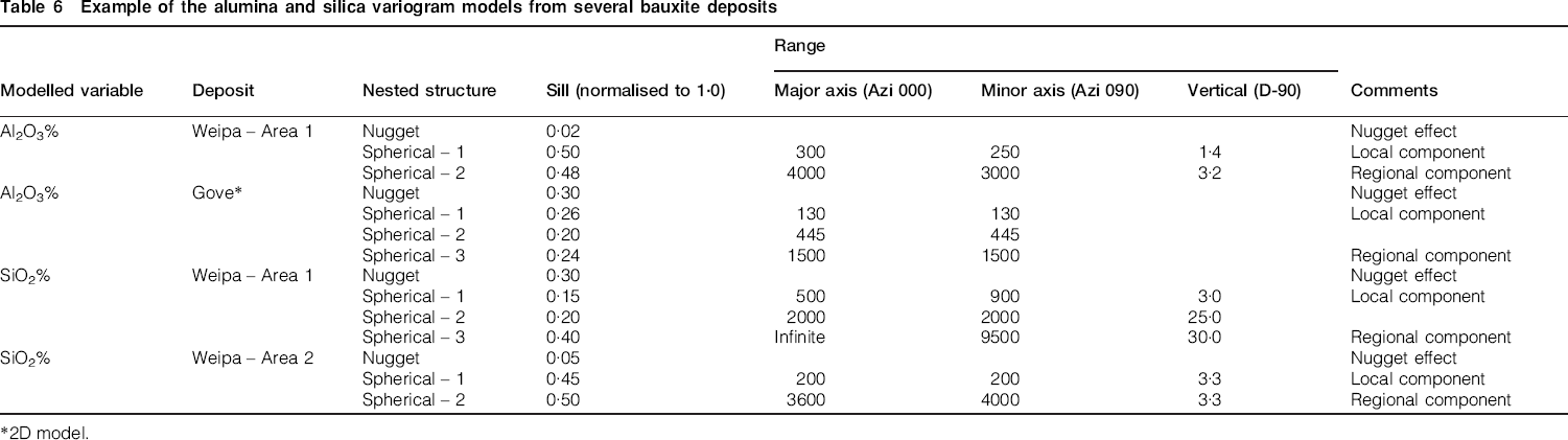
2D model.
Search neighbourhood
Search neighbourhood architecture is set using variogram model parameters. The search ellipse is oriented along the variogram axes. The horizontal radii of the search ellipses are chosen close to the variogram ranges denoting the local components of the variogram models. The vertical radius needs to be narrow in order to accurately reproduce the vertical profile of the bauxite seams.
Model verification
A standard procedure to verify the estimated grades is based on the direct comparison of the block grades with corresponding sample grades. Drillhole samples and the modelled blocks are grouped into large panels drawn across the entire deposit. Average grades are calculated for each panel using all samples within the panel and compared to the average grade of this panel estimated from the block model. Estimated average grades are plotted on a diagram against coordinates denoting the centre of the panel (Fig. 14). The diagram is usually referred to as a spider diagram.
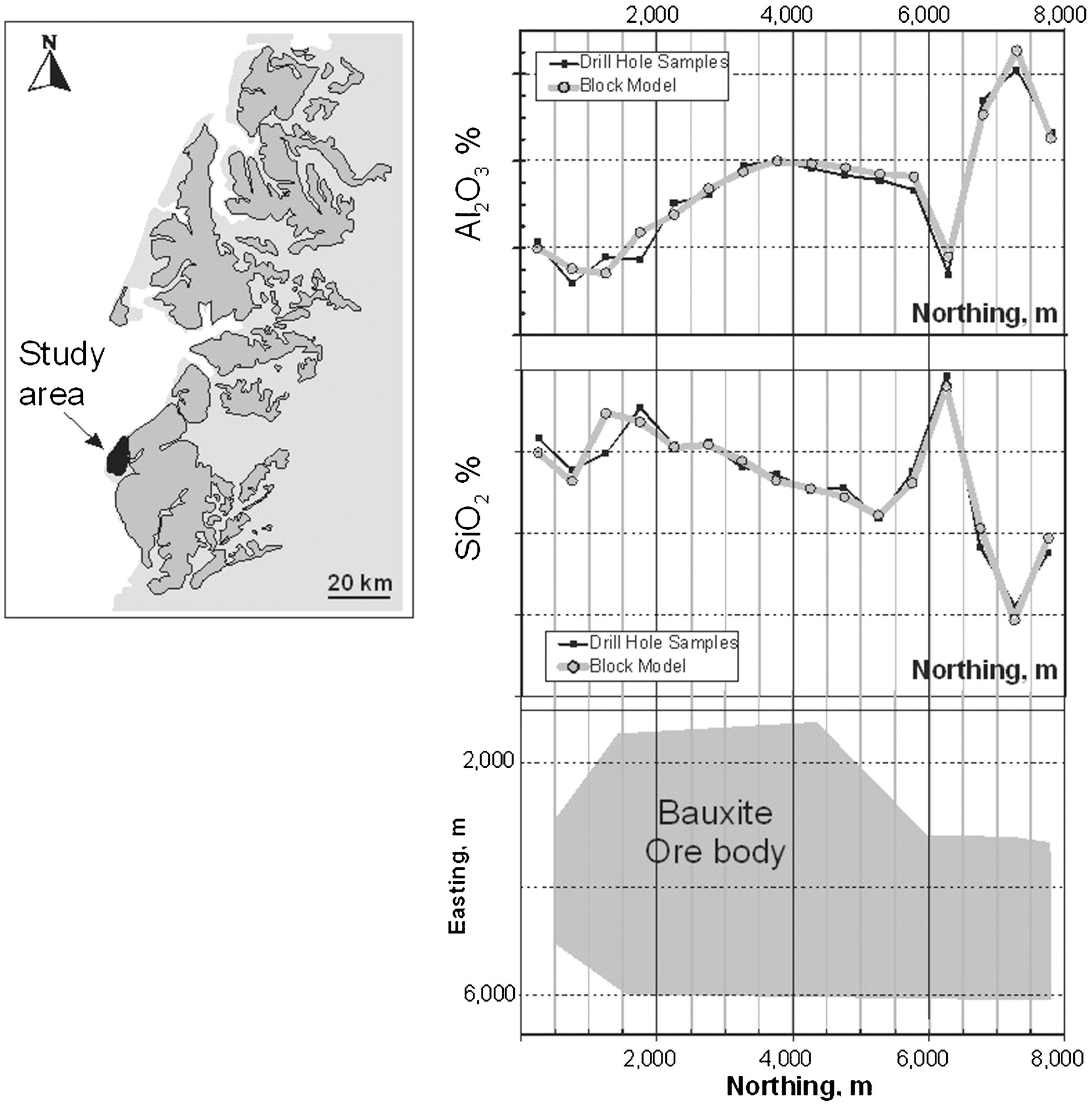
Validation of the estimated block model grades using the spider-diagrams. Estimated Al2O3 and SiO2 grades are averaged by 500 m thick panels, sliced across the domain and compared with their corresponding sample grades
Classification
Bauxite mineralisation is classified as a resource if chemical and mineralogical compositions meet project specific cut off criteria. The most commonly used cut off is 30 to 50% of Al2O3. Bauxite also should be low in SiO2 usually less than 10%.
The drilling grids are used for classification of the bauxite resources by confidence categories (Table 2). In the past, the grids have been chosen empirically, based on general resource estimation practices and reconciliation of reserves by production. However, at present, many sites have reviewed their historical drill grids with geostatistical criteria. A common approach for the geostatistical classification of mineral resources is based on integrating production rates, resource estimation errors, and confidence levels, into a single and coherent system (Parker, pers. comm.). It was implemented by the current authors for the classification of resources at the Weipa, Andoom (Abzalov and Bower, 2009) and Sangaredi mines (Abzalov, 2011) and is used at the Amargosa project (Abzalov, 2011). It was also tested at the Gove deposit (Abzalov, 2010). Classification criteria are as follows:
measured resources include mineralisation for which the grade and tonnage of the volume representing the quarterly production is estimated with ±10% error at 95% confidence level
indicated resources include mineralisation for which the grade and tonnage of the volume representing the annual production are estimated with ±10% error at 95% confidence level
inferred resources include mineralisation for which the global tonnage and grade are estimated with ±30% error at 95% confidence level.
The studied variables include Al2O3, SiO2, and the thickness of the bauxite seam. Footwall contact is also modelled and uncertainty of the footwall topography is geostatistically quantified. The rationale for choosing these variables for modelling is as follows:
Al2O3 is the main metal setting the economic value of the bauxites
SiO2 represents the main metallurgically deleterious component controlling the product types
bauxite thickness is the main variable controlling the volume and tonnage of the ore.
the accurate modelling of the footwall contact topography is important for both accurate estimation of the ore tonnage and dilution control.
Mining and metallurgical considerations
Mining parameters
Bauxite mining has particular considerations arising from the unique features of the bauxite deposits. They are mined by open pits method which are commonly shallow but cover large areas up to several hundred square kilometres. The open pits are often operated using a free digging approach (Weipa) because bauxite ores are usually hosted in soft non-consolidated lateritic sequences. The definition of bauxite resources and, in particular, their conversion to reserves, requires the following mining conditions to be taken into considerations:
haulage of bauxite ores represents one of the main mining costs therefore the choice of the optimal mining fleet and optimisation of haulage routes are crucial aspects of mine planning
despite the large mining areas and production rates exceeding 10 Mt/year, bauxite ores are mined at a vertical selectivity of 0·25 to 0·5 m which is needed to control the dilution by footwall material
grade control at the production stage may not be practical therefore pre-production infill drilling is usually used for grade control purposes and should be budgeted as an operational cost
pit slope stability is rarely an issue for bauxite mines.
Metallurgical characterisation
In early exploration stage, bauxite characterisation is made using samples from drillholes. These tests, although preliminary in nature, allow a basic characterisation of the metallurgical properties of the bauxite, and the construction of predictive models of their behaviour in the refinery.
When projects matures, usually at the pre-feasibility and feasibility stages, specialised refinery characterisation testwork is undertaken focussing on the behaviour of the bauxite in a given refinery. This type of work is generally done with the representative bulk sample, which is tailored for a particular refinery. Refinery characterisation of bauxite includes the following tests:
chemical and mineralogical characterisation of the crude bauxite
estimation of the bauxite grindability and quantification of the Bond Work Index
estimation of the particle size distribution with an objective to determine the optimal mesh size for bauxite beneficiation
characterisation of the pre-desilication behaviour of the bauxite by silica dissolution and DSP precipitation. The test usually includes a simulation of bauxite processing flow sheet at the given plant conditions
characterisation of the alumina extraction and impact of the deleterious components, in particular iron and silica. The behaviour of other impurities present in the bauxite ore is also studied
characterisation of the bauxite behaviour at the refinery, and the estimation of refinery parameters, including recovered alumina, refinery caustic consumption and red mud loading. This test requires the simulation of the entire bauxite processing flow sheet at the given plant conditions
a special study is made to characterise extractable organic carbon, oxalate formation rate and carbonate formation rate
the settling behaviour is studied by estimating the mud settling rate, mud compaction and overflow clarity.
Representativity of the bulk samples should be ensured regarding their spatial distribution and composition (Abzalov, 2013b).
Footnotes
Acknowledgements
The authors would like to thank management of the Rio Tinto Alcan for their permission to publish this paper. Critical reviews of the manuscript by S. Hancock, A. Abzalov, M. Boyle, C. DeVitry and an anonymous reviewer of the Applied Earth Science journal are gratefully acknowledged.