
Abstract
The corrosion resistance of two high chrome wear facings, manganese cold workable steel and heat treated white cast iron, was investigated. The addition of Cl− to the aqueous solution unexpectedly improves the corrosion resistance. Tribocorrosion experiments show that the current density increases but with magnitudes of no importance in industrial vertical roller mill applications. However, these corrosion magnitudes might show significant material losses in other industrial applications such as marine industries including oil drilling. The investigated wear part materials are not specifically designed to withstand abrasive marine conditions; however, the applied scientific approach might be used on such materials.
Introduction
Vertical roller mills (VRMs) are comminution units primarily used in the cement industry for finish grinding of rocks (Fig. 1). For raw material VRMs, the media in contact with the wear parts is usually a mixture of limestone, clay and quartz sand. The quartz sand will act as an abrasive on the wear parts and rapidly abrade the surfaces changing the geometry. The wear rate of an average industrial VRM (200 t h−1 capacity) is ∼5 g ton−1. Hence, during 1 h of operation 1000 g of wear part material is lost due to abrasion. The VRM is usually employed in a closed circuit mode and will both size reduce, separate and dry the raw materials. The VRM uses hot (200°C) kiln gasses to dry the raw materials and has a capacity to handle materials containing up to 20% moisture. As the moist raw materials enter the VRM, they have the ability to get in contact with the wear parts before the moisture is removed. Moreover, water is added in front of the rollers to stabilise the grinding bed. Therefore, two sources of moisture are apparent in the VRM and it is investigated whether this will result in corrosion of the wear part materials.
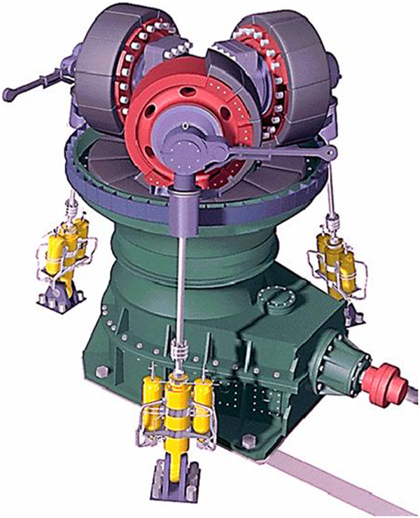
Main components of FLSmidth ATOX VRM: The horizontal circular table is driven by electrical motor while raw materials are added on table The raw materials are drawn underneath rollers during operation and the frictional force between table–bed–roller assembly ensures that rollers will turn without any external power supply
Vertical roller mills are equipped with wear parts of either high chrome cast alloys or welded wear facings, the latter showing improved abrasive wear resistances. Tribocorrosive research studies on these materials employed in VRMs seem to be non-existing. Researchers have dealt with corrosive wear in similar industries; however, the conditions cannot be fully compared to those experienced in VRMs.
Pitt1 examined the corrosive wear of a high carbon low alloy steel using an abrasive slurry. Watson2 studied the corrosive wear behaviour of a high chrome white cast iron using the same wear apparatus as Pitt.1 Neville3 investigated the corrosive–erosive effects of both Stellite and cast iron in an aggressive aqueous slurry. Neville4 thoroughly analysed the corrosive behaviour of high chromium white cast irons at different temperatures; however, no tribocorrosion experiments were conducted. Zumelzu5 performed corrosive experiments of high chromium cast iron alloys in acidic conditions (pH 5·2). Tang6 examined the corrosive sliding wear behaviour of high chromium cast iron using a commercially available wear test apparatus.
Two different high chromium Fe based welded wear facings, a high chromium cast iron and cold workable manganese steel were examined to determine their corrosion resistance during operation in a VRM. The cast iron is a multiple phase heat treated high chromium white cast iron containing a martensitic matrix and coarse Cr7C3 carbides (10-200 μm, hardness ∼1500 HV). The wear facings are specially designed weld overlays imitating conventional castings. However, the wear facing molten pool is easier to control and the development of hard phases is more favourable compared to castings. Hence, wear facings usually show a better wear resistance compared to castings. Cold workable manganese steels are designed to work harden (and thus become harder) at the surface as a result of material impact. The main interest of this study is the abrasion resistant wear facings/castings and the manganese steel is only analysed for comparative studies.
Experimental
A raw material sample was measured to have a pH of ∼10. To imitate this pH, a 1M sodium carbonate buffer (NCB) with a pH of 10·0 was chosen as a representative aqueous media. Fe is stable in both the neutral and alkaline pH range and thus a lowering of the corrosion media pH would probably yield the same results. Furthermore, it was argued that small amounts of chloride are inevitable in the water entering the VRMs. It was thus decided to conduct experiments with both the NCB alone and with NCB mixed with 250 mg L−1 Cl− (the maximum chloride threshold for drinking water suggested by WHO7). To imitate the abrasive conditions in the VRM, a 3M Scotch–Brite (Type 6448, SiC abrasive, hardness 2600 HV) abrasive sponge was used for the experiments. It is assumed that during the experiments, the abrasiveness of the SiC particles will not decrease significantly due to the hardness ratio between the wear part and the pad. The potentiostat used in these experiments is a Gill AC (ACM Instruments) with the supplied standard software. Each of the four wear part materials was cut into cubes of 1×1×1 cm and a piece of wire was soldered to one face. The cube was subsequently moulded into epoxy with the wire extending from the rear of the cast. Each sample was polished to obtain a smooth surface (P1000). Basically the experimental assembly comprises a container holding the aqueous solution. The specimen support is attached to the bottom of the container and the electrical wire is connected to the potentiostat. A standard hydrogen electrode (SHE) is submerged into the solution and positioned as close as possible to the specimen surface. For the tribocorrosion experiments a subassembly comprising a specially designed cylindrical rod, an electrical motor with variable speed control and a Scotch–Brite pad is used. The Scotch–Brite is attached to the rod, submerged into the solution and pressed against the specimen with a predetermined force. During testing, both the force and the rotational speed can be changed (Fig. 2).
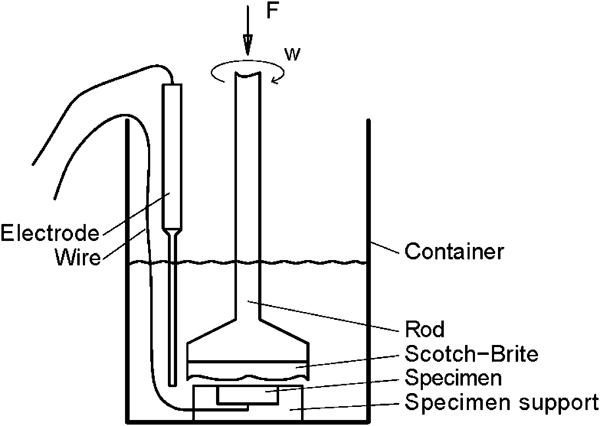
Experimental assembly
The samples were exposed to three different corrosion experiments:
open circuit potential (OCP) measurements. These measurements determine the corrosion potential at non-wear conditions. Measurements were conducted both with and without chloride added to the NCB. The aqueous solution was stirred at 80 rev min−1.
polarisation measurements. With a sweep rate of 10 mV min−1, the current density was measured to detect passivation and corrosion speeds (at non-wear conditions). The sweep was initiated at OCP −30 mV (to determine the position of the anodic curve) and finished at OCP +300 mV (the potential will probably not increase further in the VRM). Measurements were conducted both with and without Cl−. The aqueous solution was stirred at 80 rev min−1.
tribocorrosion measurements. By fixing the corrosion potential obtained in the OCP measurements, the current density was measured while abrading the surface. The pressure was varied between 16 and 41 kPa at discrete steps. The rotational speed of the abrasive sponge was either 80 or 160 rev min−1. Measurements were conducted both with and without Cl− using the following procedure:
with Cl−: 80 rev min−1, varying abrasive pressures.
without Cl−: 80 or 160 rev min−1, constant pressures.
Discussion
From data sheets and scanning electron microscopy analysis the chemical analysis of SA1, SA2, WA1 and PR4 was obtained (Table 1).
Nominal chemical composition of wear part materials*, wt-%
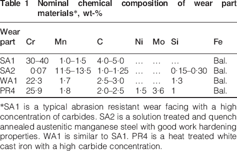
*SA1 is a typical abrasion resistant wear facing with a high concentration of carbides. SA2 is a solution treated and quench annealed austenitic manganese steel with good work hardening properties. WA1 is similar to SA1. PR4 is a heat treated white cast iron with a high carbide concentration.
Open circuit potential (non-wear)
Overall SA1, SA2 and PR4 are similar in their OCP (carbides generally increase the potential); however, WA1 diverges with its lower OCP (approximately −170 mV) and it is argued that material defects (pores) control this behaviour (without Cl−). SA1 shows the most stable behaviour indicating that Cl− solutions will form a more stable passive layer increasing the corrosive resistance. For the Mn rich SA2, the slow increase in potential is probably due to the formation of MnO2 which can be verified by examining.8 Furthermore, there is the possibility that Fe2O3 is formed simultaneously and will cover a fraction of the surface. PR4 shows a tendency towards pitting (Fig. 3).
Open circuit potential with and without Cl− (non-wear conditions); operating parameters: 23°C, agitation 80 rev min−1, pH = 10·0
Polarisation measurements (non-wear)
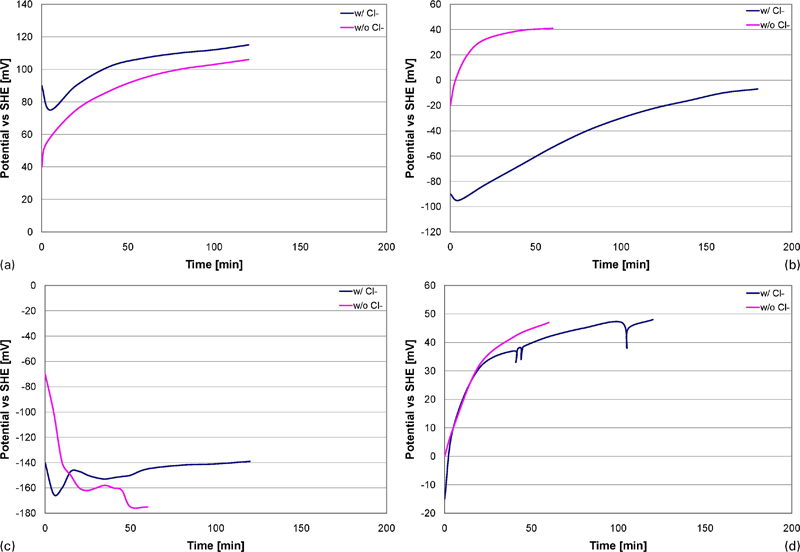
The similarities observed in the OCP measurements are of course repeated in the polarisation measurements because WA1 shows the lowest E corr. SA1, SA2 and PR4 show approximately the same normal behaviour in the entire region. Current density is not influenced significantly by the addition of Cl− (Fig. 4a, b and d). WA1 shows the most extreme and unusual effects of Cl− addition (Fig. 4c). In the entire cathodic region, the corrosion resistance benefits from Cl− by lowering i corr approximately one decade. However, E corr is still very low compared to the other materials. For WA1 it is argued that the addition of Cl− will rapidly accelerate the corrosion forming an inhibiting oxide layer. Next, due to this oxide layer, the corrosion speed is rapidly lowered. For comparison it is observed that i corr of PR4 is approximately two decades smaller than that of WA1. PR4 thus shows a corrosion resistance approximately 100 times better compared to WA1 (Fig. 4c and d).
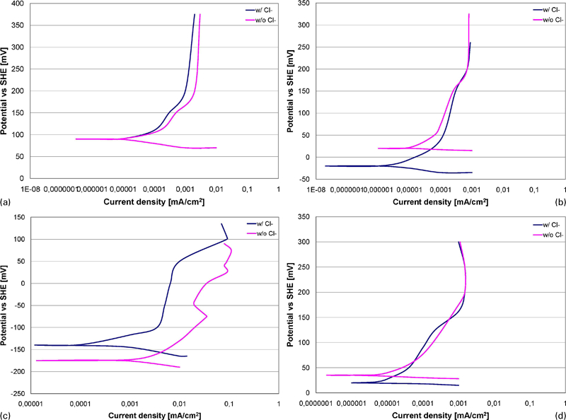
Characterisation of four wear part materials by polarisation measurements with and without Cl− (non-wear conditions); operating parameters: 23°C, agitation 80 rev min−1, pH = 10·0, sweep rate 10 mV min−1
Tribocorrosion
In general, as soon as the abrasive Scotch–Brite pad establishes contact with the specimen surface, i corr increases instantly. It can be argued that the formed passive layer is removed and the virgin surface is exposed. After a while i corr reaches equilibrium where the formation and removal of oxides becomes constant. The largest increase in current density is observed for SA1 and SA2 (approximately two decades). Furthermore, the addition of Cl− will surprisingly decrease the current density for all materials reaching almost a decade for SA1. The advantage of the addition of Cl− can be explained in a few ways: During abrasion, tiny oxide crystals are formed and constantly removed as a result of the rotating pad. The mechanical action ensures that the crystals stay very small and the oxide layer will thus become more dense than normal. The mechanism could be further intensified by mechanical impression of the oxides into the surface. A detailed description of each wear part material explains the similarities and differences:
as observed during OCP and polarisation measurements, SA1 benefits from the addition of Cl− to the solution. Increasing the speed of the abrasive pad increases i corr; however, increasing the pressure has almost no effect (Fig. 5a). It can be concluded that Cl− acts as a catalyst causing the formation of a dense and stable passive layer.
the behaviour of SA2 is similar to SA1 except that the abrasive speed has no influence in a Cl− depleted solution (Fig. 5b). Furthermore, as observed during the polarisation experiments, the rapid decrease in current density after a change in pressure is probably due to the formation of MnO.Fe2O3 (calculated using a Pourbaix diagram).
WA1 shows the highest overall i corr and during abrasion Cl− has almost no influence. Again, as previously observed, increasing the speed will increase i corr, but increasing the load has no effect. The noise at the beginning (0-20 min) can be related to the pores previously mentioned (Fig. 5c).
PR4 is similar in its behaviour compared to WA1; however, it shows some run-in noise at the beginning of the Cl− solution. This initial noise is not considered being significant for the understanding (Fig. 5d).
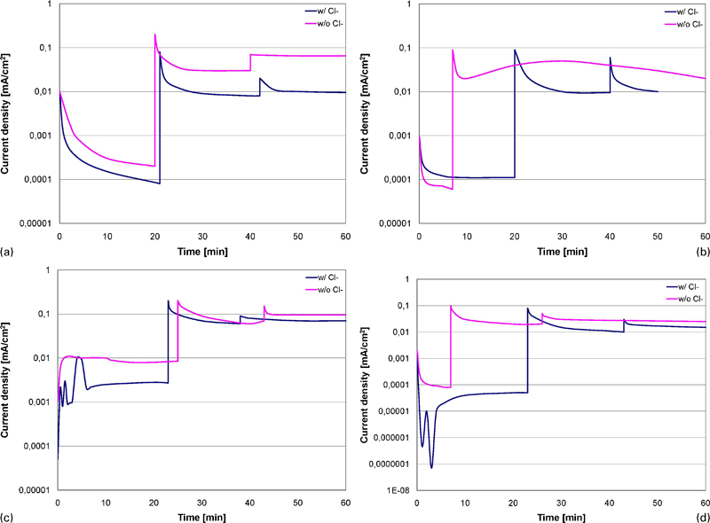
Tribocorrosion measurements showing current density versus time (with and without Cl−); operating parameters: 23°C, agitation variable, pH = 10·0, potential raised 300 mV above OCP
When inspecting the micrographs of a specimen exposed to tribocorrosion, it is readily seen that the matrix alone is corroded. The chromium carbides stay unaffected and thus it can be assumed that the area ratio between the chromium carbides and the matrix can be used for a general estimation of wear rates. Moreover, it is also observed that the chromium carbides are cut by the SiC particles and hence they also experience degradation. For the micrographical studies, the PR4 specimen has been used as a reference, but the other materials show similar properties (Fig. 6).
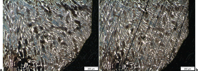
Micrographs (optical microscopy) of PR4 high chrome casting: abrasive marks from Scotch–Brite pad are readily visible (b)
Pourbaix diagrams
The Pourbaix diagrams also known as E-pH diagrams are a two-dimensional visual representation (map) of stable compounds in aqueous solutions (Fig. 7). The diagram conveniently shows the immune, passive and corrosive conditions, and thus a metal/aqueous system can be tailored to avoid dangerous operating conditions. The diagram is based on classical Gibbs free energy thermodynamical data. Although thermodynamics cannot predict kinetics, it has been commonly accepted that the compounds with the lowest Gibbs free energy will always dominate in a region of interest in the diagram. The classical Pourbaix diagrams are concerned with metal–hydrogen–oxygen (M–H–O) systems. However, in most industrial cases, the aqueous solution might contain other compounds (e.g. chloride) and as a result different complex compounds are formed and the region of immunity and passivity might be shifted drastically. Furthermore, the metal might be an alloy containing various elements and likewise each possible compound needs to be computed individually to determine a stable system. The complex Pourbaix diagrams in this study were calculated using a software program (HSC Chemistry 5·0 by Outokumpu). In this study, the metallic wear part is a composite where a ceramic (Cr7C3) is embedded in a ferrous matrix, and thus the wear part can be regarded as comprising two different materials.
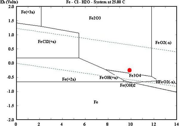
Fe–Cl–H2O Pourbaix diagram: Fe molality 1·0×10−6, Fe pressure 1·0 and Cl molality 7·1×10−3, Cl pressure 1·0; for WA1 potential in tribocorrosion experiments is approximately −170 mV, pH≈10 and result is formation of Fe2O3
Estimation of corrosion speed
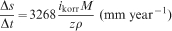
As the worst case scenario WA1 has been investigated to estimate the corrosion speed. WA1 comprises mainly Fe and Cr, but Cr is present as non-corrosive chromium carbides. The carbides are estimated to cover ∼50% of the surface. In the WA1 hard facing composite, Fe is vulnerable to corrosion and thus a Pourbaix diagram based on Fe and Cl has been calculated to examine the behaviour as function of both pH and potential (Fig. 7). As mentioned previously, the tribocorrosion experiments were conducted at OCP and thus a potential of approximately −170 mV applies. At this setting the corrosion product is Fe2O3 (oxidation stage 3) and the current density is 0·1 mA cm−2. By means of Faradays laws, the corrosion speed (cm s−1) can be estimated as follows9

Conclusions
Contrary to common belief, it seems that the addition of Cl− has a positive effect on the corrosion resistance as it promotes the formation of a dense passive layer. This passive layer, however, will only lower the current density by less than a decade. Independent on the type of aqueous solution, the application of a rotating abrasive pad increases the current density by one to two decades indicating that mechanical action has a large influence on the corrosion properties. Only a slight load is necessary to remove the passive layer; increasing the load further has almost no influence on the current density.
Increasing the rotational speed of the Scotch–Brite pad during tribocorrosion measurements has only a slight influence in increasing the current density by ∼1/5 decade. It can be concluded that moist raw materials do not influence the wear rate significantly (∼1·6 mm year−1). The conventional abrasion mechanism outperforms the corrosive wear because the normal wear rate easily reaches 100 mm year−1.