
Abstract
A diagnosis and rehabilitation study of two reinforced concrete structures located in coastal areas in two different climates is presented. Building 1 was constructed in the north of Chile in 1949, at a distance of 600 m from the coastline, in a seismic zone. Cracks, steel corrosion, loosening of concrete cover and slab deformations have been identified. Building 2 was constructed in Habana City, Cuba, in 1973. It is located at <100 m from the shore. The structure of building 1 shows severe localised damage: loosening of reinforced cover and intense reinforcement bar corrosion due to high deposits of sea salts. High chloride and sulphate content in the concrete mass, low compressive strength in walls and slabs, high level of steel corrosion and zones with the existence of rust instead of steel were reported. A structural rehabilitation project to ensure an increase in service life is not possible. On the contrary, in case of building 2, a possible rehabilitation procedure is recommended. Elimination of chloride contaminated concrete and the use of special mortar is an option, and electrochemical chloride extraction and incorporation of sacrificial anodes is another. An important conclusion is made: the use of chloride and sulphate contaminated aggregates is more dangerous than the penetration of these two contaminants from the external environment for buildings constructed in coastal zones.
Keywords
Introduction
Corrosion of reinforcing steel represents the major cause of degradation of reinforced concrete structures. It also involves a potential safety hazard because concrete pieces can fall from height due to reinforcement corrosion. The corrosion process leads to several combined effects: longitudinal cracking of concrete cover due to expansive corrosion products, steel cross-section reduction and the degradation of the steel–concrete bond. As a result of these effects, the service life and the load bending capacity of reinforced concrete elements become considerably reduced.1 – 4
Premature deterioration caused by reinforcement corrosion is being reported in an increasing number of structures. In general, this corrosion is caused by the destructive attack of chloride ions penetrating the concrete by diffusion and/or other penetration mechanisms, by incorporation into the concrete mixture, by carbonation of the concrete cover of the reinforcement or a combination of these.5
The conclusions of the DURAR project ‘The influence of environmental action on reinforced concrete durability: DURACON’, with the participation of 11 countries (Latin America, Spain and Portugal), and based on the exposure of reinforced and non-reinforced specimens in several microclimates, showed that in marine atmospheres, chloride content in the environment is the most decisive factor when evaluating the probability of reinforcement corrosion. It is important to note that this project did not analyse the influence of aggregate contamination.6 – 8
It is well known that the corrosion of the steel bars in reinforced concrete caused by the ingress of chloride ions is the most severe problem affecting the durability of concrete constructions, especially in coastal and marine environments; however, carbonation induced corrosion is probably more widespread when considering all reinforced concrete structures. When the concrete cover is damaged by sulphate solution attack, which is commonly encountered in field constructions, chloride ion will rapidly access the surface of the steel bar embedded in the concrete. The attack of sulphates on concrete is due to two principal reactions: the reactions of Na2SO4 and Ca(OH)2 to form gypsum and the reaction of this gypsum with calcium aluminate hydrates to form ettringite. In addition, it is noticed that MgSO4 reacts with all cement compounds, including C–S–H, thus decomposing the cement and subsequently forming gypsum and ettringite.9
The aggressive attack of sulphate and chloride ions is of considerable scientific and technological interest because it is one of the main factors responsible for concrete damage. The effect of seawater on concrete deserves special attention because sea structures are exposed to the simultaneous action of chemical deterioration processes.1
Deteriorated reinforced concrete structures exposed to marine environmental conditions revealed that salt water and/or contaminated aggregates had probably been used for concrete mixing in the Chilean building. The concrete components were most likely originally contaminated with salts due to contact with soil at the site, because in the north of Chile some other constructions have shown the same problem.
Thaumasite and ettringite are compounds that are increasingly found as deterioration products of cementitious materials subjected to sulphate attack. Thaumasite, and especially ettringite, has been abundantly reported in relation to concrete deterioration as well as, more recently, to the deterioration of cementitious mortars for masonry and plasters. Even without ettringite formation, there is loss of strength and adhesion of the cement paste due to decalcification of C–S–H in the process.3
The combined role of chloride and sulphate ions in the deterioration of concretes is not well known. Limited experimental data recorded by Saeed and Al-Amoudi demonstrated that the damage caused in concrete by sulphate attack is reduced in the presence of chloride.10
Beaudoin et al. also reported, for concrete stored in a composite solution for 12 months, a decrease in chloride ion ingress rate into certain concretes due to the concurrent presence of sulphate and chloride ions in the solution,11 and Dehwah et al. considered that the presence of sulphate ions in the chloride solution did not influence the time for initiation of chloride induced reinforcement corrosion, but that the rate of corrosion increased with increasing sulphate concentration.12
Chloride diffusion and deterioration of concrete could change under different circumstances. The carbonation phenomenon on concrete probes in areas near the sea shore has also been identified. Castro et al. proposed that the higher humidity and salt content in the air close to the shore (50 m) apparently contribute to blocking the carbon dioxide access in the pore network of the concrete. Higher carbonation constants were found in areas far from the shore. In concrete exposed to areas of high chloride deposits, the hygroscopicity of this element helps to maintain the saturation of the pore network. The carbonation constant decreases as the compressive resistance increases in concrete probes at different water/cement ratios.13
On the other hand, Haque et al. considered that in concrete structures near to the Arabian Gulf, the carbonation profile showed high values in the structures near the shore due to the high temperatures and humidity up to 12 km from the coastline, where the carbonation profile increased with distance.14
In the present paper, a diagnosis and rehabilitation study of two reinforced concrete structures located in coastal areas of two different countries having different climates is presented. Building 1 was constructed north of Chile in 1949, 600 m from the coastline, in a seismic zone. Cracks, steel corrosion, loosening of concrete cover and slab deformation have been identified in this construction. Building 2 was constructed in Havana City, Cuba, in 1973. It is located <100 m from the shore. The structure shows serious localised damage: loose reinforced cover and intense reinforcement bar corrosion due to high deposits of sea salts. Carbonation of the concrete has also been observed (though not severe).
Materials and methods
A detailed inspection of the structural state of both buildings was carried out. Photographs are presented below.
For compressive strength, the values were determined according to NCh1037.15
For carbonation depth, the phenolphthalein test was carried out using RILEM CPC-18.16
For corrosion potential, the standard method ASTM C 876-09 gives criteria about its values (half cell potential) of reinforcement steel in concrete: if the corrosion potential is more positive than −200 mV (Cu/CuSO4 reference electrode), then there is <10% probability of corrosion; if it is more negative than −350 mV, then there is >90% probability to actively corrode. For values between −200 and −350 mV, the corrosion reaction is considered uncertain.17
In this work, a Cu/CuSO4 reference electrode and high impedance millivoltmeter was used to measure the corrosion potential of the steel rebars. The steel bars were found using a Ferroscan System scanner, and in the same section, the specimens were extracted for compressive strength, and later, the same specimens were used for chloride and sulphate ion analysis and carbonation depth.
In the quantitative determination of free chloride in the concrete dust, the Volhard volumetric method was used, in accordance with the UNE 112-010-94 standard. The analysis of sulphate ions in the concrete, using the same dust used for chloride ions, was performed in accordance with NCh1444/1.Of80.18
Building 1
To study the state of building 1, with a view to proposing a rehabilitation system in case of major damage or repair of damaged areas, as expected before visiting the building, instructions were followed as outlined in the Red DURAR recommendations, which detail the steps to be followed in the diagnosis of a structure. In this case, the diagnosis began with a review of all the previous available information on the building. Engineers who had performed diagnosis 10 years earlier made a study based on the mechanical properties of the concrete, and in some cases, they found steel corrosion, without specifying whether the steel corrosion was detected in the slabs or the walls, or whether the corrosion was only on the more exposed steel, which is that the walls are exposed to sea winds.
The study began with a photographic survey, differentiating external and internal walls, slabs, beams and columns, from the underground up to the last of the three floors of the building. Areas were selected: slabs, columns and beams that were apparently in poor condition due to deformation and cracks, and then they proceeded to detect the structural steel using a scanner: Ferroscan System, which provides information on the location of the steel, its depth and sections. This is important for all rehabilitation processes, so that the whole building, including its girders, is analysed.
As the building was in use at the time, it was not possible to drill in certain areas, and thus, the most representative areas were selected.
Samples of repair mortars were analysed; these were commonly used and in some slabs were found at thicknesses up to 40 cm due to repairs, which were intended to correct the deformation of the slabs.
Destructive and non-destructive tests, such as compressive strength and reinforcement scans, were carried out to compare the strength capacity of some of the deteriorated elements with the strength capacity that a structure should have in order to comply with the corresponding Chilean standards.
Additionally, with regard to the projection of the building's service life, the corrosion potential of the residual steel was calculated, and concrete specimens were extracted for testing. These samples were tested for compressive strength, resistance to water absorption, carbonation depth and chloride and sulphate ions analysis for both the concrete and the surface cover and repair mortars.
The samples were extracted in different areas and depths from the surface toward the interior in walls and slabs.
Building 2
This building was constructed in 1973 using a prefabricated technology known as ‘slip forms’. Chloride penetration and carbonation based on phenolphthalein indicators were determined at different points in the building. The corrosion potential and the corrosion rate of the rebars were also determined. Concrete quality is acceptable where no localised damage is observed.
Results and discussion
Building 1
Figure 1 shows a general view of building 1. An inspection was made on each of the building's four levels, beginning with a preliminary visual inspection without the performance of any tests, differentiating between the structural vertical elements, the walls and columns, and the horizontal elements, the beams and slabs, as they present different demands, service performance and importance in the building's structural safety. The inspection allowed the identification of the columns on the lower levels with longitudinal cracks of small width located on the joints with the beams, together with generalised cracking and visible deformation of the horizontal elements, beams and slabs in the areas of maximum bending moments (positive and negative) ( Figure 1 Figure 2 Figure 3 Figure 4 Figure 5 Figs. 1-6).
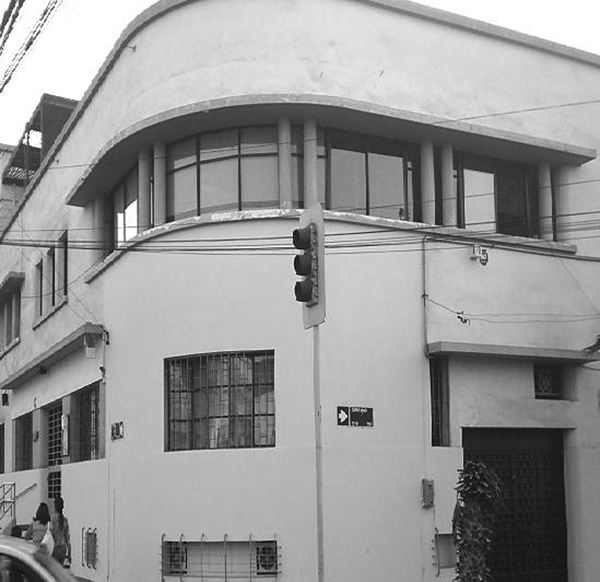
Building constructed in 1949
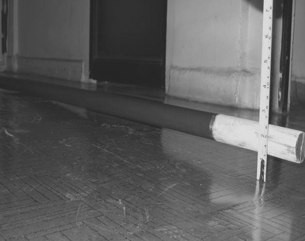
First level slab with central deformation up to 5 cm
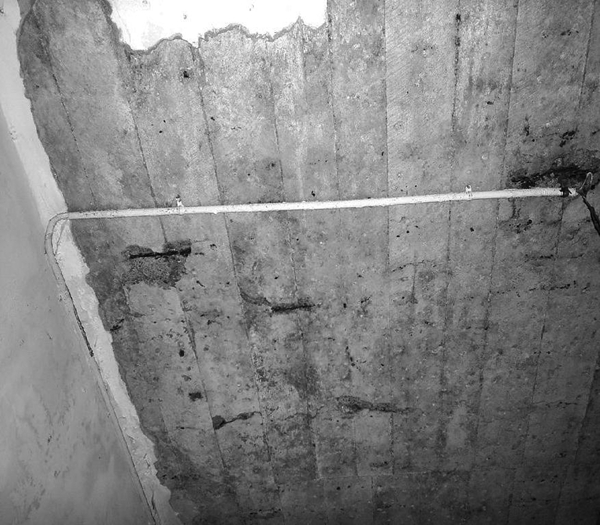
Underground level column longitudinal
Second floor slab with steel corrosion cracking
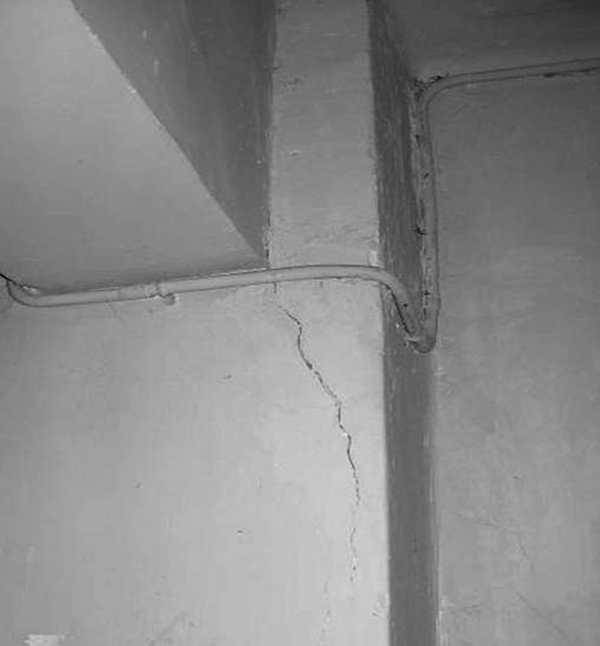
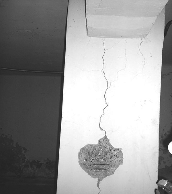
Wall with typical fissures
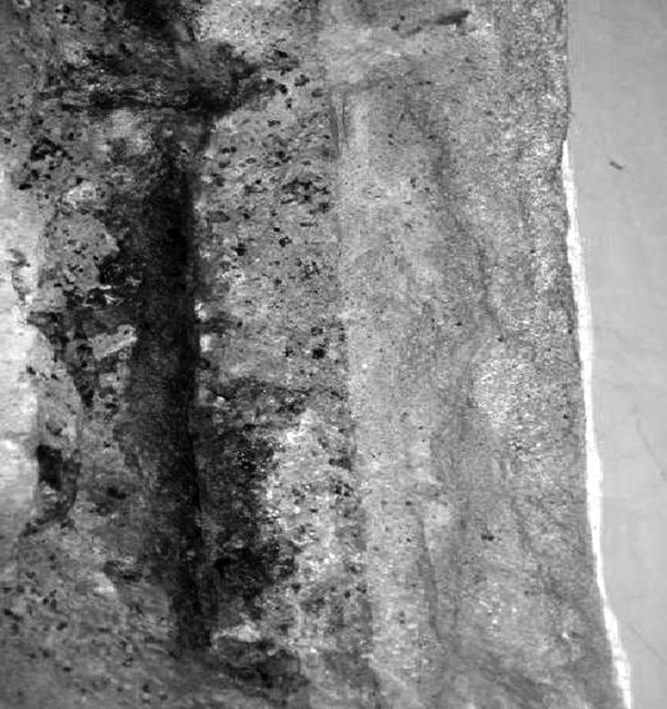
Visible steel corrosion
In Fig. 5, an example of fissures, and in Fig. 6, after a simple blow, it can be seen that the concrete has no adherence, and the steel have been completely corroded away. The results for chloride and sulphate ion content are presented in Table 1.
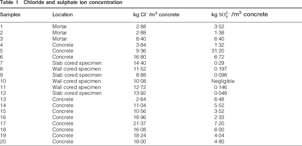
Chloride and sulphate ion concentration
 /m3 concrete
It is important to note (in Table 1) that for the total of 20 evaluations of chloride and sulphate, 17 of these show a higher amount of chloride than sulphate. This means that it is very probable that the effect of chloride should predominate over sulphate, although the interaction between both ions can also be considered. Chloride averages 11·62 kg m−3, and the sulphate average is 4·56 kg m−3.
With regard to compressive strength, assuming that concrete of the same quality was used for all the structural elements, a concrete of 20 MPa (204 kgf cm−2) was determined for the current state of the building (Table 2), whereas the samples extracted and tested 10 years ago reported 260 and 305 kgf cm−2 (25·5 and 30·0 MPa).
Compressive strength determined on different samples obtained from building 1
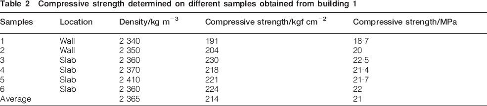
The number of samples extracted 10 years ago is lower than those taken recently and, as a consequence, less representative; however, it could be supposed that concrete was of type H25, unlike the present results, showing H20 concrete. The difference in 56 and 101 kgf cm−2 in compressive strength means that the structure is on the lower limit of concrete used for public buildings nowadays.
It is possible to confirm that the chloride and sulphate ion contents in many samples exceed the Chilean standard limits by 1000%: 1·20 kg Cl− m−3 of concrete and 0·600 kg  m−3 of concrete. The content of both ions did not present penetration profiles; they were found throughout the mass of the concrete.
The combined effect of chloride and sulphate ions on the deterioration of the reinforced concrete is not well studied. In this building, the attack of chloride ions is delayed and become evident after >50 years; it is possible that the presence of sulphate ions slowed the corrosive effect of the chloride ions, as reported by Beaudoin et al.11 In addition, due to the existence of C3A in the cement paste, the chloride ions react with this to form chloroaluminates, then the chloride ions will not be corrosives. This binding between C3A and chloride ions in concrete probably will breakdown with a reduction in pH, as caused by carbonation, like in the Chilean building whose carbonation is between 3 and 5 cm.19
The compressive strength of the concrete decreased from 25 to 20 MPa over 10 years. The current compressive strength (20 MPa) is lower than the strength specified for this reinforced concrete structure. The steel was scanned using the Ferroscan System FS10 and showed the non-existence and/or decrease in the steel reinforcement section in areas of maximum bending moments in beams and slabs. This test was verified with the removal of the concrete cover in the most problematic areas.
With regard to the columns and walls, the scanning showed less damage in the steels in comparison with the slabs and beams. It was possible to note that in the areas of higher steel strength, there were higher levels of corrosion of the reinforcement bars.
Owing to carbonation, the pH significantly decreases, and a possible break of bonds existing between chloride ions and chemical compounds of cement is possible. It is reported that the bounded chlorides under pH decrease constitute a risk to corrosion initiation in reinforcing steel.13
Capillary absorption values were obtained using the Fagerlund test, and the results correspond to the quality of the real concrete, with values for the coefficient of absorption between 0·78 and 1·0 gm−2 s−1/2, which is in accordance with a compressive strength concrete of 20 MPa. The corrosion potential values for steel bars were close to −550 mV with respect to the Cu/CuSO4 electrode. These values show high probability of corrosion according to ASTM C876-91, which indicates that under corrosion potential values more negative than −350 mV, the corrosion probability is high.
The analysis of the results quantifies an important failure in the strength capacity to bending moments of the studied slabs, where the capacities barely overcome their capacity, without the minimum safety factors demanded by Chilean standards for public building structures.
In addition, the corrosion of the upper steel reinforcements of the slabs, in the joint areas with beams, generates plastic connecting rods, changing the structural configuration: reducing tensions in damaged sectors, the highest negative bending moments, and increasing tensions in areas where the reinforcement is present, the highest positive bending moments ( Figure 7 Figs. 7 and 8).
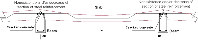
Jointing areas between slabs and beams after corrosion process
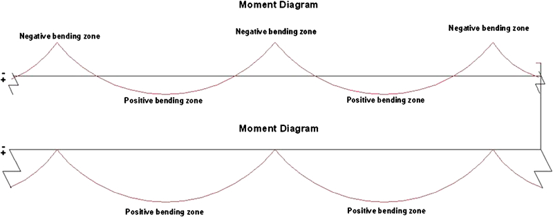
Redistribution of bending due to disappearance of steel in negative bending areas
Building 2
Figure 9 shows a general view of the location in front to the seashore of building 2. Different localised damages are presented in Figure 10 Figs. 10 and 11.
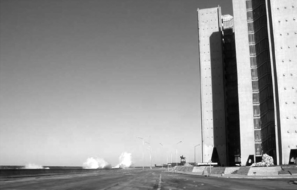
Location of building 2 in front to seashore in Habana City
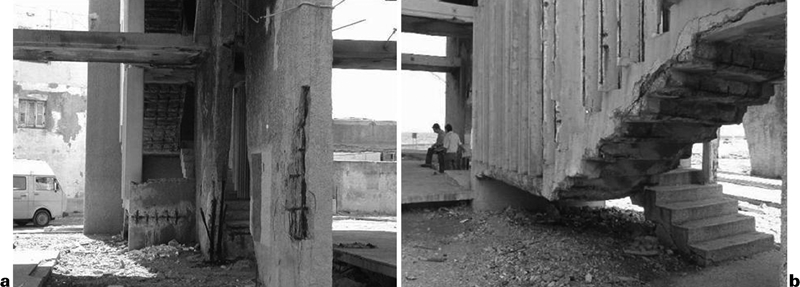
a loosened concrete cover and b localised corrosion of reinforcement bars on building 2
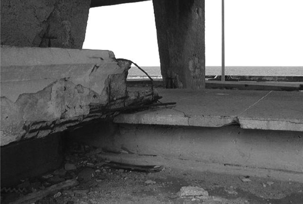
Localised damage in slabs in building 2
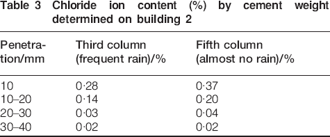
The data presented in Table 3 show the influence of rain in chloride penetration. Higher levels of chloride penetration are found in the column rarely submitted to rain in comparison with the column that frequently receives the influence of rain. This means that the effect of rain diminishes chloride penetration in building 2.
Chloride ion content (%) by cement weight determined on building 2
With respect to compressive strength, it is reported that, at the moment of construction, Portland cement was used for the columns to obtain a value of 400-450 kg m−3. The relative percentage of chloride penetration assuming the probable amount of cement used is presented in Table 4.
Chloride penetration (%) to cement mass determined on building 2
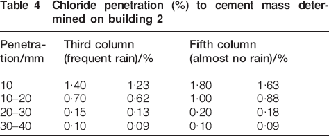
Chloride penetration coming from the external environment occurs by diffusion. Significant chloride penetration values are reported only up to a depth of 2 cm. This explains why concrete damage occurs in zones where, due to construction defects, the concrete cover was equal or lower than 2 cm.
This mechanism is evident in concrete with good compactness, homogeneity and consistency in spite of the high level of chloride ion deposits present in the environment. In these types of structures located close to the sea without any screening effect, chloride ions tend to penetrate from the combination of capillary suction and diffusion mechanism. The combined mechanism means that there is greater penetration of these ions reaching a larger concentration in the reinforcement bars and corrosion begins quickly. The fundamental cause of the corrosion linked deterioration of this structure is based on the effect of dragging presented by the concrete at the moment of placement. 20 20,21
The corrosion potential values of the reinforced steel for concrete cover of <2 cm thick were around −380 mV ( ) (no measurements were carried out for covers thicker than 2 cm). This shows a high probability of corrosion according to ASTM C876-09. However, the corrosion rate values determined were between 0·1 and 0·5 μA cm−2, indicating moderate corrosion levels according to the clasification range established in the thematic network durability of concrete.22
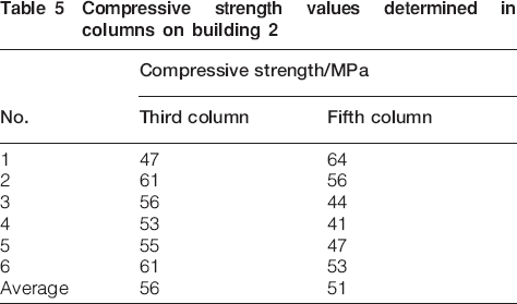
The compressive strength in both columns, presented in Table 5 after 29 years, shows that the concrete in building 2 has maintained a good load bending capacity.
Compressive strength values determined in columns on building 2
On the other hand, the carbonation profile was lower in the column frequently subjected to rain, with a lower carbonation constant rate on the concrete, as shown in Table 6. It shows that in the column frequently subjected to rain, the higher humidity in the pore network of the concrete block decreases the penetration of carbon dioxide in comparison with the column, which does not receive frequent rain.
Depth of carbonation values in columns of building 2
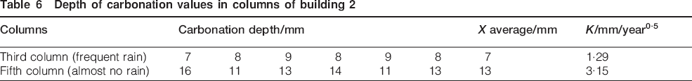
The carbonation constant obtained from the expression of the square root confirms that, in accordance with the classification intervals in Table 7, building 2 has presented a good concrete, particularly in the column subjected to high frequency of rain.
Typical values of K (mm/year0·5) for poor, medium and good quality concretes

Under these conditions, localised reparation could be carried out. Special mortars are proposed, including those containing silica sand and polymers as they offer conditions of low porosity and difficult access for chloride ions.
Conclusions
The most important conclusions about building 1 are the following.
The current building condition is characterised by an evident decrease in the bending resistant capacity of the beams and slabs due to generalised steel reinforcement corrosion in combination with the reduction in concrete compressive strength, which particularly affects walls and columns, generating functional problems in the use of the building and, principally, an important risk of its use, as the structural performance barely overcomes the service use and does not reach the minimum safety factors demanded by Chilean standards for this type of structure.
The building's damage, the high concentration of chloride and sulphate ions present in all the concrete, the reduce of pH together with the periodic presence of humidity, due to flaws in the drainage system and the high humidity of the local environment, lead to the deduction that the concrete degradation will continue to increase due to the presence of sulphate ions and corrosion of the residual steel caused by the chloride ions.
The presence of chloride ions can be resolved using sacrificial anodes, but the high concentrations of sulphate ions in all the concrete cannot be extracted by any proven technique at present, with only experimental solutions existing.
Considering that any rehabilitation project has two main objectives, i.e. to provide compressive strength to the structure during its service life and to guarantee restitution of the structural capacity, in line with the use of the building, the resources of the rehabilitation project and other authorised Chilean laboratories do not recommend rehabilitation for this structure, as it cannot be performed in a structure with the combined presence of chloride and sulphate ions in the concrete mass: the most important factors of risk for the durability of a reinforced concrete structure.
In addition, with regard to building 2, the most important conclusions are the following.
The causes of corrosion in this building are due to the effect of chloride ions coming from the environment. This effect can be appreciated in the area of concrete cover of <2 cm due to faults during construction of the building. When the cover thickness is higher than 2 cm, no damage is observed.
The concrete quality is good, and taking into consideration that corrosion damage is localised in places of low concrete cover, repair can be carried out using mortars designed for highly aggressive sites.
In general, carbonation is low in the building; however, it is higher in columns not submitted to frequent rain. The corrosion potential values for reinforced steel at cover thickness of <2 cm show high probability of corrosion, but the corrosion current is in the range of moderate corrosion.
General conclusions
Although the main cause of deterioration of the two buildings is the presence of contaminants in the concrete, there is a significant difference between the causes of corrosion, as in one of the buildings the contaminants are present throughout the concrete mass because they were introduced in the aggregates used in making the concrete. In the other building, chloride ions are present only in concrete cover up to a depth of 2 cm as these ions come from the external environment. Corrosion of the steel has caused low bending resistance in building one, while corrosion of steel is presented only in the reinforced steel on places having low concrete cover, and no mechanical effect is observed. In this situation, building 1 should not be repaired, and building 2 is recommended for repair.
Footnotes
Acknowledgements
The authors gratefully acknowledge the Civil Construction School, Pontificia Universidad Católica de Chile, and Pontificia Universidad Católica de Valparaíso, and the cooperation given by Dr R. Engelfried, Dortmund University, Germany, in the evaluation of building 2 and the advice given for its repair.