
Abstract
The corrosion of N80 tubing steel was measured electrochemically in an autoclave at an overall carbon dioxide pressure of 1·2 MPa. Both potentiodynamic polarisation curves and electrochemical impedance data were analysed to obtain the relevant kinetic parameters. The influences of H2S pressure and immersion time on the corrosion of N80 were analysed in detail. The results indicate that protective sulphide scales may form at higher partial pressures of H2S and greatly decreased the corrosion rate of N80 steel as the immersion time increased. Thus, the capacitive loop shrinks gradually in the low frequency region and eventually shifts to a single capacitive loop at low H2S concentration, whereas at higher H2S concentrations, the capacitive loop gradually disappeared, and diffusion controlled processes then predominated owing to the formation of a protective corrosion scale at longer immersion times.
Introduction
The control of corrosion of carbon steel is a major challenge in oil and gas production environments. Thus, corrosion failures can lead to costly repairs, plant shutdowns as well as health and environmental hazards. The presence of typical production gases, such as CO2 and H2S, can increase the corrosiveness of produced fluids and, hence, the severity of corrosion of carbon steel.1 – 3 Many studies have investigated the CO2–H2S–H2O system in order to better understand the corrosion of steel, surface films/scales and corrosion mechanisms involved. Some early research4 in this field has suggested that a low concentration of H2S (<30 ppm) in CO2 saturated aqueous solution could accelerate the corrosion rate significantly in comparison to corrosion in concentrations and higher temperatures (>80°C) when a protective film forms. 4 4,5 In a Norwegian study,6 it was suggested that this effect of H2S could be significant only in the low pH range (pH<5).
In general, the reasons behind the ‘H2S effect’ on CO2 corrosion are not entirely understood. It has been speculated that adsorbed sulphide species and/or sulphide films affect the corrosion rate of mild steel through a catalytic or a galvanic effect.6 Several research efforts7 – 12 have attempted to elucidate the mechanism of CO2/H2S corrosion; however, the understanding of the underlying processes is still lacking. In addition, several studies13 – 16 have demonstrated that the electrochemical behaviour of iron in acidic solutions containing H2S can be investigated by means of alternating current impedance measurement. Although results have been reported on the corrosion characteristics of mixing CO2 and H2S gases, many of the influences, such as the effects of H2S partial pressure and immersion time, are still indistinct. This research work will focus on a systematic electrochemical investigation of the influence of trace amounts of H2S on the behaviour and mechanism of anodic and cathodic processes in CO2/H2S solution.
Experimental
Material preparation
In these experiments, the corrosion process was monitored with two different electrochemical measurement techniques: electrochemical impedance spectroscopy (EIS) and potentiodynamic polarisation. Experiments were carried out using a C-276 Hastelloy autoclave made by Cortest Company under various conditions. Figure 1 shows a schematic diagram of the autoclave with a three-electrode electrochemical arrangement. An EG&G Princeton Research (PAR) model 5210 lock-in amplifier and a PAR model 273A potentiostat/galvano stat was used to undertake the experiments. A three-electrode electrochemical cell system with Ag/AgCl saturated reference electrode and platinum auxiliary electrode was used. The cylinder electrodes (exposed surface area = 1·767 cm2) were made of N80 tubing steel, whose chemical composition is 0·24C–1·19Mn–0·22Si–0·013P–0·004S–0·036Cr–0·021Mo–0·028Ni–0·006Nb–0·017V–0·019Cu (wt-%). A simulated production brine, with concentrations of the main ions of 50 g L−1 Cl− and 20 g L−1 Ca2++Mg2+ (10∶1), was prepared using analytic reagents of NaCl, CaCl2 and MgCl2 and dissolved in distilled water. Before the tests, the surfaces of the test specimens were abraded with silicon carbide papers progressively up to 800 grit, degreased with acetone and then rinsed with absolute alcohol. All the specimens were weighed using a precision of 0·1 mg and finally stored in desiccators before used.
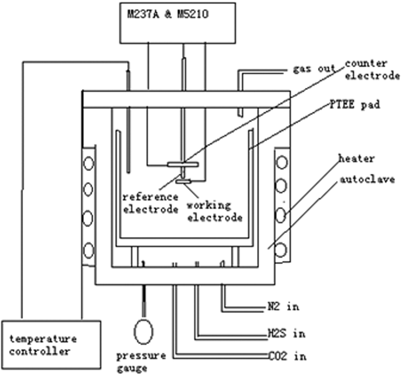
Schematic illumination of electrochemical system in autoclave apparatus
Electrochemical measurement
After deoxygenation by bubbling nitrogen, the test solution was injected into the above autoclave. Then, the solution was heated to 100°C. The CO2 and H2S were then introduced into the autoclave to the expected partial pressures. Potentiodynamic polarisation was measured with a scan rate of 0·166 mV s−1. The EIS measurements were carried out at open circuit potential (OCP) using 5 mV peak to peak amplitude perturbation and a frequency range of 100 kHz to 5 mHz. In addition, the EIS measurements at –50 or +50 mV(OCP) on N80 steel were undertaken to probe the cathodic and anodic processes directly. The EIS data were fitted by ZSimpWin software.
Results and discussion
Polarisation measurements
The potentiodynamic polarisation curves of N80 tubing steel at 100°C in brine containing CO2 (1·2 MPa) and H2S (0·014 MPa) are shown in Fig. 2. After 2 h of immersion, it is shown that the self-corrosion potentials shift in the negative direction on the addition of H2S, which indicates that the addition of H2S is having a greater effect on the cathodic kinetics than on the anodic kinetics. From the data reported in Table 1, it is clear that H2S gas can accelerate the kinetics of cathodic reaction based on the decreased Tafel slope. It is because only when in a pure CO2 environment does CO2 dissolve in water, hydrate and form carbonic acid, and then the carbonic acid formed partly dissociates as H+ and  ions participating in the cathodic reaction. However, when purged with H2S, the electroactive substances resulting from H2S dissociation for the cathodic reaction in the presence of CO2 are less than that only in the pure water medium. Therefore, it results in the effect on the cathodic Tafel slopes in the mixing gases of CO2 and H2S to be lower compared to the effect on the anodic Tafel slopes.
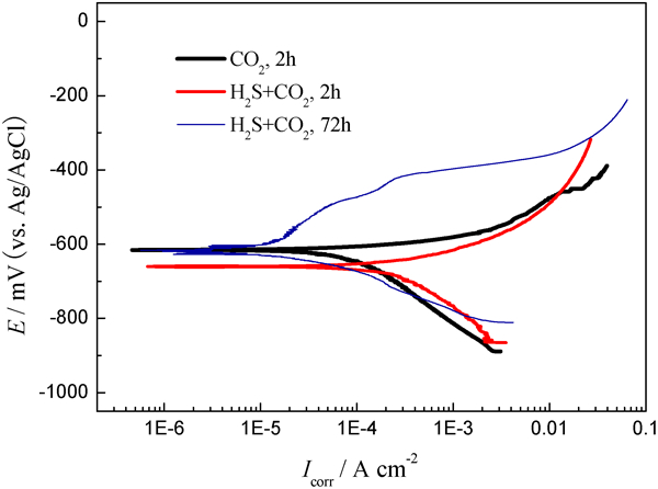
Polarisation curves measured on N80 tubing steel at 100°C in solution containing CO2 (1·2 MPa) and H2S (0·014 MPa)
Kinetic parameters of polarisation curves obtained at 100°C in brine containing CO2 (1·2 MPa)+H2S (0·014 MPa)
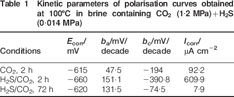
In addition, the corrosion current density is about five times larger than that of the H2S free solution after 2 h of immersion, which demonstrates the accelerated corrosion effect of H2S on bare steel. However, the dynamic parameters significantly change after 72 h of immersion. For example, the free corrosion potential shifts in the positive direction with respect to that after 2 h of immersion, as shown in Table 1, and the anodic kinetics indicates the formation of a protective corrosion. Thus, it can be observed from Fig. 2 that a passivation process on the anodic branch of the polarisation curve is present at 72 h of immersion. It should be mentioned that the corrosion current density greatly decreases from 609·9 to 7·9 μA cm−2, which is even smaller than the value of 92·2 μA cm−2 in the pure CO2 medium. The corrosion scales of sulphides have an effective protection and greatly decrease the corrosion rate.
Figure 3 shows the polarisation curves obtained in the solution with different pressures of H2S at 100°C and a pressure of CO2 equal to 1·2 MPa. When the partial pressure of H2S is 0·002 MPa, the polarisation behaviour is similar to that in pure CO2 medium, which suggests that CO2 corrosion mainly controls the overall reaction process. As the H2S pressure increases up to 0·01 and 0·014 MPa, both cathodic and anodic reactions are promoted. Therefore, in comparison to the pure CO2 case, the H2S corrosion primarily controls the polarisation process. In Fig. 3, the corrosion rate increases with the increase in the partial pressure of H2S. It can be supposed that when the partial pressure of H2S is very small, sweet corrosion dominates, but increasing amounts of H2S, over a threshold level, accelerate the corrosion rate.
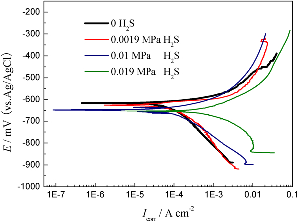
Polarisation curves measured at 100°C in solution with CO2 (1·2 MPa) and different amounts of H2S
Electrochemical impedance spectroscopy measurements
Anodic process
Figure 4 shows the EIS measured at +50 mV(OCP) on N80 steel in the solution containing CO2 (1·2 MPa)+H2S (0·014 MPa) at different immersion times with the corresponding equivalent circuits. The sharp and size of these impedance spectra strongly depended on the partial pressure of H2S. For the N80 steel immersed after 2 h in the testing medium, Fig. 4a demonstrates an obvious capacitive arc at high frequencies, indicating a double layer capacitance as well as a small capacitive arc at low frequencies that results from the adsorption of H2S on the surface of the electrode. It is suggested in the literature that the heterogeneous surface roughness and the non-uniform distribution of current density on the surface may be related to it.17 In this case, no corrosion scales occur, and the reaction is controlled by the activation effect. After 12 h of immersion, the impedance behaviour undergoes various changes. In the impedance spectrum shown in Fig. 4b as the impedance spectra from Fig. 4c and d, there are single capacitive loop at high frequencies and Warburg impedance resulting from the semi-infinite diffusion found in the low frequency region. Therefore, it is easy to judge that the anodic reactions are also controlled by ion diffusion through corrosion scales.
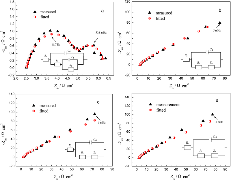
Electrochemical impedance spectroscopy plots measured at +50 mV(OCP) on N80 steel in solution containing CO2 (1·2 MPa) and H2S (0·014 MPa) at different immersed times
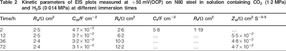
As it is well known, when H2S is dissolved in water, it partially dissociates as H+ and HS− ions; probably, HS− has a greater chemisorption ability than  and OH− ions,18 and a great degree of coverage induces impedance spectroscopy in the low frequency region. For the 12-72 h of immersion, the fitting equivalent circuit is the same, and the fitting data from the impedance plots are shown in Table 2. For the equivalent circuit, C dl, R s, R t and Z w are the double layer capacitance, the solution resistance between the working and reference electrodes, the charge transfer resistance of corrosion scale and the Warburg impedance respectively. However, the fitting parameters for 12-72 h of immersion show some differences. The important parameter of the R t value has an obvious increase as the immersion time increases. The result indicates that the corrosion scale forms on the N80 steel surface, and the scale becomes more protective.
Kinetic parameters of EIS plots measured at +50 mV(OCP) on N80 steel in solution containing CO2 (1·2 MPa) and H2S (0·014 MPa) at different immersion times
The anodic dissolution process in CO2/H2S corrosion can be described as follows


Cathodic process
Figure 5 shows the EIS and the equivalent circuit at –50 mV(OCP) of N80 steel in the solution with CO2 (1·2 MPa) and H2S (0·014 MPa) at different immersion times. It is shown in Fig. 5 that the cathodic impedance spectra present the characterisation of single capacitive loop and Warburg impedances and the corresponding equivalent circuits. According to the fitted equivalent circuits, some important parameters are listed in Table 3. There are multitudes of cathodic active substances, such as H+,  , H2S and HS−, but only one kind of substance participates in the cathodic reaction. It is obvious that the HS− ions are related to the anodic reaction, and the cathodic reaction is mainly controlled by H2S when the constant quantities of CO2 (1·2 MPa) and H2S (0·014 MPa) are kept. Hence, the cathodic reaction in the present work is shown as follows

Electrochemical impedance spectroscopy plots measured at –50 mV(OCP) on N80 steel in solution with CO2 (1·2 MPa) and H2S (0·014 MPa) at different immersion times
Kinetic parameters of EIS plots measured at –50 mV(OCP) on N80 steel in solution with CO2 (1·2 MPa) and H2S (0·014 MPa) at different immersion times
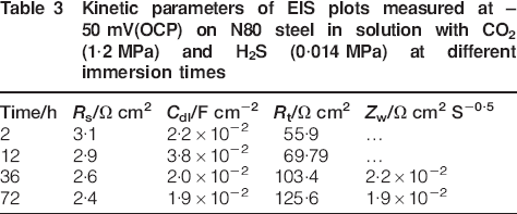
Because the solution containing CO2 and H2S is saturated, it is thought that the single capacitive reactance is possibly controlled by the activation effect of equation (6) and the Warburg impedance occurring induced by the ion diffusion through the solution at the beginning stage. After 36 h of immersion, the Warburg impedances occur. Because of the trace consuming quantities of H2S, the phenomenon is related to the corrosion scales. In Table 3, the Z w value decreases from 2·2×10−2 to 1·9×10−2 Ω cm2 S−0·5, which is in accordance with the result from the R t value, i.e. the corrosion scales have stronger impedance.
Influence of H2S partial pressure
Figure 6 shows the EIS plots of N80 steel measured at 100°C in the solution with CO2 (1·2 MPa) and different amounts of H2S (0·0019, 0·01, 0·014 and 0·019 MPa). It can be seen from Fig. 6a that as the immersion time increases, two capacitive loops occur at the initial corrosion stage, and then the capacitive loop shrinks gradually in the low frequency region and eventually shifts to a single capacitive loop when the H2S concentration is controlled at 0·0019 MPa. This is in agreement with the results of the polarisation curves, as discussed above. In this case, the inductive loop does not occur, which indicates that the addition of 0·0019 MPa H2S accelerates the adsorption of intermediates. The capacitive loop demonstrates that the diameter in the high frequency region decreases with increasing immersion time for the effect of the increased active effect related to H2S, which suggests that the corrosion rate rises.
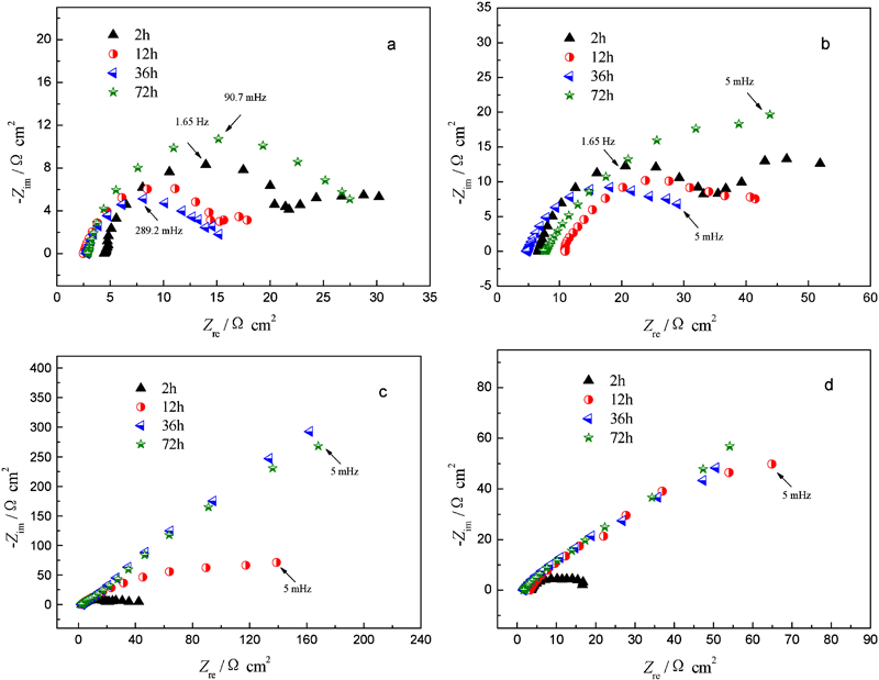
Electrochemical impedance spectroscopy plots of N80 steel measured at 100°C in solution with CO2 (174 lb in−2) and different amounts of H2S
Figure 6b shows that sour corrosion becomes the main one as the partial pressure of H2S increases, which leads to local corrosion after 36 h of immersion. Furthermore, there is a small capacitive loop in the high frequency region owing to the cracking of sulphide scales. However, the secondary products, such as FeS, FeCO3 and CaCO3, do not effectively cover the steel surface after 72 h of immersion. Therefore, the small capacitive loop reflecting the localised corrosion still exists in the Nyquist impedance diagram.
It can be observed from Fig. 6c that at 2 h of immersion, there exist two capacitive loops, and at 12 h of immersion, the characteristics of diffusion controlling are obvious. Up to 36 h, the capacitive loop reflecting the localised corrosion disappears, and diffusion controlling predominates. The Warburg impedance increases with the increase in immersion time. The results suggest that the secondary products can effectively cover the steel surface after 36 h. Similarly, the Nyquist impedance spectra from Fig. 6d have the same change trends with a bit of difference.
Conclusions
Protective sulphide scales could form and greatly decreased the corrosion rate of N80 steel as the immersion time increased. Sweet corrosion dominated the corrosion process when the partial pressure of H2S is very small, whereas sour corrosion became the main one as the partial pressure of H2S increases.
During the anodic process, the impedance spectra involved two capacitive loops at the initial stage, and then the Warburg impedance resulted from the semi-infinite diffusion that occurred in the low frequency region as the immersion time increased. The R t value had an obvious increase as the immersion time increases. The cathodic impedance spectra present the characteristics of single capacitive reactance at the initial stage, and then the Warburg impedances occur due to the formation of corrosion scales.
As the immersion time increases, two capacitive loops occur at the initial corrosion stage, and then the capacitive loop shrinks gradually in the low frequency region and eventually shifts to a single capacitive loop with low H2S concentration. At high H2S concentrations, the capacitive loop gradually disappeared, and diffusion controlling predominated owing to the protective corrosion scale formation with increased immersion time.
Footnotes
Acknowledgements
The authors want to thank the Key Laboratory Opening Fund (grant no. 06A40302) of Corrosion and Protection of Tabular Goods Research Center, China National Petroleum Corporation, for support in this work.