
Abstract
The self-corrosion and galvanic corrosion of magnesium based alloys Mg–10Gd–3Y–0·5Zr (GW103) and AZ91D coupled to carbon steel and Cu in ethylene glycol (EG) solution with and without inorganic–organic inhibitor packages Na3PO4+SDBS and Na3PO4+benzoate were investigated through measuring their open circuit potentials, coupling potentials, potentiodynamic polarisation and galvanic current densities. It was found that these two inhibitor packages effectively inhibited the self-corrosion of GW103 and AZ91D but accelerated the dissolution of the carbon steel and Cu in the EG solution. When the Mg alloys were coupled with the carbon steel or Cu, their galvanic current densities were also inhibited if the Na3PO4+benzoate inhibitor package was used in the EG solution. It is surprising that the addition of Na3PO4+SDBS accelerated the galvanic corrosion. Based on the mixed potential theory, it is believed that the variation in E corr difference between the anode and cathode and the change of their Tafel slopes after inhibitor addition should be responsible for the galvanic corrosion behaviour of these couples.
Keywords
Introduction
Magnesium alloys containing rare earth elements are becoming more and more attractive due to their high strength and ductility, which have large potential applications as light structural materials for the aerospace and automotive industries.1 It has been reported that the recently developed Mg–Gd–Y alloys exhibit higher specific strength and better creep resistance than conventional Mg and Al alloys at room and elevated temperatures.2 – 9 The main drawback of magnesium alloy is their low corrosion resistance due to their highly negative electrochemical potential compared with other metals. In practice, direct electrical contact between Mg alloys and other metals is required or unavoidable in some industrial designs because of mechanical and electrical demands.10 For example, in addition to self-corrosion, it has been realised that the galvanic corrosion of magnesium alloy coupled to other metals is one of the difficult obstacles in the application of magnesium alloys as structural materials in automotive industries.11 – 20
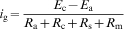
When two different metals are coupled, the metal with a relatively negative potential will be an anode and undergo accelerated anodic dissolution by the other one with a relatively positive potential. The galvanic corrosion rate of two coupled metals in direct contact with identical size can in theory be determined by10
In the auto industry, corrosion is always a major issue in the engine cooling system. Considerable research has been carried out in this area.13 – 18 Currently, the main composition of a conventional coolant is 30-70 vol.-% ethylene glycol (EG). Inhibitors are essential components in a coolant to protect traditional engine materials, such as cast iron, aluminium, copper, steel and lead–tin solder.19,20 However, traditional inhibitors including imidazole, amine, borax, carboxylate, etc.,21 – 23 which were developed for traditional materials, such as steel, copper or aluminium, do not give adequate protection for magnesium alloys.24 In a cooling system, both self-corrosion and galvanic corrosion can occur. There is a need for a new coolant that can provide a high level of protection for magnesium alloys against their self-corrosion and galvanic corrosion. Inhibitors may behave differently in inhibiting the self-corrosion and galvanic corrosion of an Mg alloy. It is important to examine their inhibition performance under self-corrosion and galvanic corrosion conditions separately.
In our previous study, inorganic–organic inhibitor packages,24 phosphate+sodium dodecylbenzenesulphonate (SDBS) and phosphate+benzoate were evaluated to have high inhibition efficiency on an Mg alloy in an EG solution. Therefore, in this paper, they were selected in order to investigate their inhibition effect on the self-corrosion and galvanic corrosion of GW103 and AZ91D magnesium alloy alloys.
Experimental
Materials preparation
The materials used in this experiment were GW103 (Mg–10·32Gd–3·60Y–0·59Zr, wt-%), AZ91D (Mg–7·19Al–0·67Zn–0·30Mn), carbon steel (Fe–0·43Cu–0·25Si–1·70Mn–0·21Mo, wt-%) and pure Cu (99·95 wt-%) (the compositions were determined by an inductively coupled plasma emission spectrometer). For electrochemical measurements, specimens were made into Φ11·3×50 mm cylindrical electrodes. An electrical wire was inlaid into a drilled hole in the electrode, and the joining area was sealed with epoxy. The electrode was mounted in Teflon leaving an area of 1·0 cm2 exposed. The exposed sample surface was abraded with a series of water silicon carbide paper to 1200 grit, then ground using 0·5 μm metallographic abrasive paper, degreased in acetone, rinsed with ethanol and then dried in cold air.
Solutions
Blank EG solution was prepared using 50 vol.-%EG and distilled water. Inhibitors used in this study were analytical grade Na3PO4+benzoate and Na3PO4+SDBS with a total concentration of 1 000 ppm. The inhibitor containing solution was mixed with the EG solution at 1∶1 ratio (i.e. 50 vol.-%EG and 50 vol.-%. inhibitor containing solution). No deaeration was applied, and the cell was closed during tests.
Electrochemical measurements
The coupling potential (CP) was recorded relative to a saturated calomel electrode, while the Mg alloy electrode was in electrical connection with the carbon steel or Cu electrode. The galvanic current i g between the Mg electrode and the carbon steel or Cu electrode was monitored with a zero resistance ammeter. The distance between the anode and cathode was maintained constant at 1·4 cm.
For OCP and polarisation curve measurements, a conventional three-electrode system was employed with Mg, carbon steel (or Cu) as a working electrode, saturated calomel electrode as a reference electrode and Pt foil as a counter electrode. Polarisation curves were obtained potentiodynamically from −700 to 800 mV(OCP) at a scanning rate of 1 mV s−1 after the working electrode was immersed in the solution for 0·5 h to reach its steady OCP.
All the above experiments were performed at 25±1°C and repeated for at least three times to ensure their reproducibility. The most typical curves from these repeated measurements were selected and presented in figures.
Results and discussion
Open circuit potentials of Mg alloys
Open circuit potentials of GW103 and AZ91D in blank EG solution and that with sodium phosphate+SDBS and sodium phosphate+benzoate are displayed in Fig. 1.
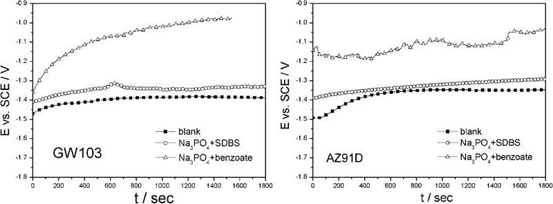
Open circuit potentials of GW103 and AZ91D in blank EG solution and solutions with sodium phosphate+SDBS and sodium phosphate+benzoate respectively
The OCP shifts to the noble direction and gradually gets to a constant value in the blank solution. The addition of the inhibitor packages leads to increased values of OCP. The OCP with phosphate+benzoate is more positive than that with phosphate+SDBS. In general, the increase in OCP with time in the blank solution could be associated with the adsorption of EG molecules at the Mg alloy interfaces. The adsorption of EG molecules may repel water molecules and protect the Mg alloy surface to some extent.19 The OCP behaviour after addition of the inorganic–organic inhibitors should be associated with formation of a relatively uniform deposited or adsorbed film on the Mg alloy surfaces.24 The film reduces both the cathodic and anodic reaction rates; the anodic processes could be retarded more significantly.
Open circuit potentials and CPs of carbon steel and Cu
Figures 2 and 3 show the OCPs of carbon steel and Cu as well as their CPs when they are coupled to Mg alloys in the inhibitor containing EG solutions. When inhibitors were added in the blank EG solution, the OCP of carbon steel exhibited a sudden drop of about 50-100 mV, while the OCP of Cu decreased by ∼100 mV. If they are coupled with Mg alloys, the OCPs of carbon steel and Cu become CPs, which shift negatively, falling in the range between the OCPs of carbon steel (or Cu) and Mg alloys respectively. The figures also show that the addition of the inorganic and organic inhibitors leads to decreased OCPs of carbon steel and Cu and increased CPs of carbon steel–Mg and Cu–Mg couples. The addition of sodium phosphate+benzoate has a stronger effect on the increase in OCPs of Mg alloys, CPs of Mg alloys coupled to carbon steel and Cu and the decrease in OCPs of carbon steel and Cu respectively. According to equation (1), the decrease in the OCPs of carbon steel and Cu and the increase in OCPs of Mg alloys mean a decreased OCP difference E c−E a between the anode and the cathode. This implies that the addition of sodium phosphate+benzoate could more significantly reduce the driving force of the galvanic corrosion.
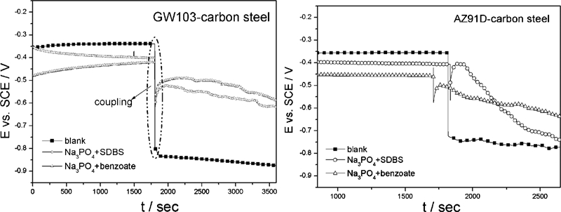
Open circuit potentials and CPs of carbon steel coupled to GW103 and AZ91D in blank EG solution and solutions with sodium phosphate+SDBS and sodium phosphate+benzoate respectively
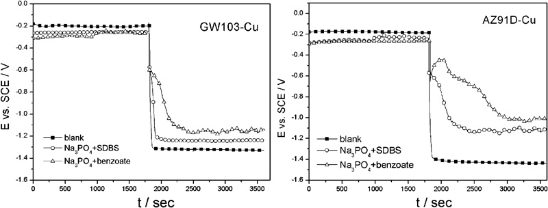
Open circuit potentials and CPs of Cu coupled to GW103 and AZ91D in blank EG solution and solutions with sodium phosphate+SDBS and sodium phosphate+benzoate respectively
It is noted that the CPs of Mg alloy–carbon steel couples are close to the OCP of carbon steel, and the CPs of Mg alloy–Cu couple are close to the OCPs of Mg alloys. These indicate that Cu is under a more severe cathodic polarisation in the Cu–Mg alloy couples than that of carbon steel in the carbon steel–Mg alloy couples, whereas the Mg alloys are in a more severe anodic polarisation state in the carbon steel–Mg alloy couples than in the Cu–Mg alloy couples.
Polarisation behaviour of Mg alloys, steel and Cu in galvanic couples
Figure 4 shows the polarisation curves of GW103, AZ91D, carbon steel and Cu in the blank EG solution and that containing inhibitors at 25°C. The measured polarisation curves were curve fitted for their corrosion potentials and corrosion current densities. The results are listed in Table 1.
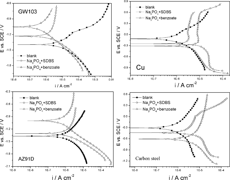
Polarisation curves of GW103, AZ91D, Cu and carbon steel in blank EG solution and inhibitor containing EG solutions at 25°C
Polarisation curve parameters of GW103, AZ91D, Cu and carbon steel in EG solutions with and without inhibitors
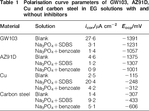
From Fig. 4 and Table 1, it can be seen that corrosion current densities i corr of AZ91D are smaller than those of GW103 in the solutions with and without the inhibitors, which means that AZ91D is more corrosion resistant than GW103. Furthermore, the values of i corr of GW103 and AZ91D decrease, and OCPs shift more positively as the inhibitors are added into the blank EG solution. The inhibitor addition reduces the anodic polarisation current densities of these two Mg alloys much more significantly than the cathodic processes. This behaviour implies that the inhibitor packages mainly inhibit the anodic dissolution process of Mg alloys. However, both inhibitor packages accelerate the corrosion rate of carbon steel and Cu. The cathodic polarisation curves of the carbon steel and Cu with addition of sodium phosphate+benzoate are less influenced compared with those of sodium phosphate+SDBS, meaning that the sodium phosphate+SDBS is worse than sodium phosphate+benzoate in terms of their inhibition performance if steel or Cu is involved in a corroding system.
As the inorganic–organic inhibitors have a synergistic effect and show an anodic inhibition behaviour on Mg alloys, the corrosion potentials of Mg alloys shift positively as shown in Table 1. However, the inhibitors somehow accelerate the anodic dissolution of Cu and carbon steel, resulting in negatively shifted OCPs of these non-Mg metals.
Galvanic current densities
Figure 5 shows the time dependence of the galvanic current densities of GW103–carbon steel and AZ91D–carbon steel couples respectively. The steady galvanic current densities before and after inhibitor addition are listed in the Table 2. Despite the small difference between their final steady current densities, the galvanic current densities of Mg alloys coupled to carbon steel in the inhibitor containing solutions exhibit the same variation trend; the galvanic current densities ascend sharply at the moment inhibitor addition and then descend back. The sudden increase and decrease in galvanic current density could be due to the disturbance of the solution or solution resistance changed by addition of inhibitor. After that, current densities gradually get stable, and the galvanic corrosion current density with addition of sodium phosphate+benzoate gets smaller than that of the blank EG solution, indicating that sodium phosphate+benzoate could decrease the galvanic corrosion rate of Mg–carbon steel couple. It is surprising that the addition of sodium phosphate+SDBS into the EG solution actually accelerates the galvanic corrosion.
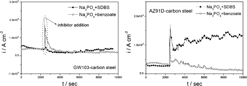
Galvanic current densities of GW103 and AZ91D coupled to carbon steel in sodium phosphate+SDBS and sodium phosphate+benzoate containing EG solutions
Average galvanic current densities of GW103–carbon steel and AZ91D–carbon steel couples before and after inhibitor addition
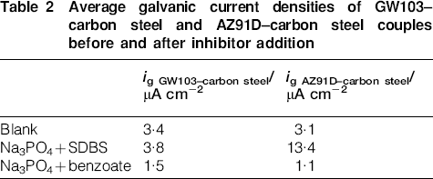
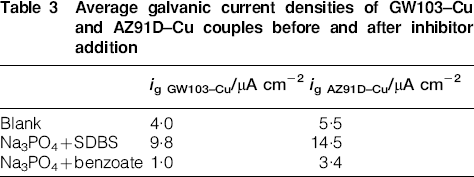
Figure 6 shows the time dependence of the galvanic current density of GW103–Cu and AZ91D–Cu couples. Their steady galvanic current densities before and after inhibitor addition are listed in the Table 3. The results show the same trend as observed in the Mg–carbon steel couple.
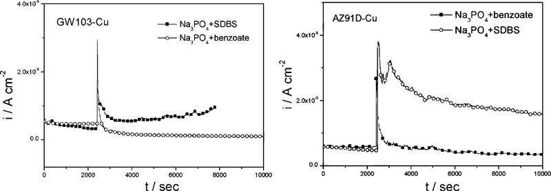
Galvanic current densities of GW103 and AZ91D coupled to Cu in sodium phosphate+SDBS and sodium phosphate+benzoate containing EG containing solutions
Average galvanic current densities of GW103–Cu and AZ91D–Cu couples before and after inhibitor addition
The above results show that the Na3PO4+benzoate package has a better inhibition effect on the galvanic corrosion of both Mg–carbon and Mg–Cu couples.
Mixed potential theory prediction
Figure 7 schematically illustrates the influence of these two inhibitors on the galvanic corrosion of Mg alloys coupled to Cu and steel.
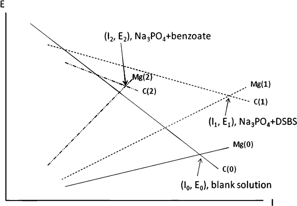
Schematic illustration of polarisation of GW103, AZ91D, Cu and carbon steel in blank EG solution and solutions with sodium phosphate+SDBS and sodium phosphate+benzoate
According to the mix potential theory, galvanic current between a galvanic couple could be predicted by the intersection of cathodic polarisation curve of the cathode with anodic polarisation curve of the anode. In this study, as the anode and cathode in the galvanic couple have equal surface areas, the mixed potential prediction can be made based on the anodic and cathodic polarisation current densities. Lines Mg (0) and C (0) represent the anodic polarisation branch of Mg polarisation curve and cathodic polarisation branch of carbon steel (or Cu) polarisation curve respectively. I 0 is the galvanic current density obtained from the intersection point of these two lines, and E 0 represents the CP of the galvanic couple. After inhibition addition, the anodic dissolution process of Mg alloys is suppressed, and a steeper slope is obtained. Meanwhile, the cathodic current density of the cathode becomes larger, and an explanate slope is anticipated. The intersection points of I 1 and I 2 represent the galvanic current densities after addition of Na3PO4+benzoate and Na3PO4+SDBS packages. E 1 and E 2 represent the CPs of the galvanic couple with these two inhibitor packages. As shown in Fig. 7, the addition of Na3PO4+benzoate has a larger influence on the anodic polarisation of Mg alloys and a smaller impact on the cathodic polarisation of the cathode. This explains the increase in the CP after addition of these two inhibitors. The addition of Na3PO4+benzoate depresses the anodic dissolution much more significantly than Na3PO4+SDBS, but it does not accelerate the cathodic process so much as Na3PO4+SDBS. Therefore, the Na3PO4+benzoate package retards the galvanic process, while the Na3PO4+SDBS package accelerates the galvanic corrosion.
Conclusions
The self-corrosion of GW103 and AZ91D Mg alloys can be effectively hindered by Na3PO4+SDBS and Na3PO4+benzoate inhibitor packages.
Both Na3PO4+SDBS and Na3PO4+benzoate inhibitor packages accelerate the self-corrosion of carbon steel and Cu.
The Na3PO4+benzoate inhibitor package has an inhibition effect on the galvanic corrosion of GW103 and AZ91D coupled to carbon steel and Cu respectively.
Both the Na3PO4+SDBS package accelerates the galvanic corrosion of GW103 and AZ91D coupled to carbon steel or Cu.
An inhibitor that can effectively retard the self-corrosion of an Mg alloy may not always effectively inhibit its galvanic corrosion. If the inhibitor is detrimental to the cathode corrosion performance, then it may deteriorate the galvanic corrosion resistance of the anode in a couple.