
Abstract
Conformal coatings are applied on printed circuit board assemblies (PCBAs) in order to protect the assembly from environmental influence and silicone-based coating is commonly used. A systematic study on the performance of silicone conformal coating in connection with process-related contaminants is the focus of this paper. Different test substrates such as plain laminate surface and a test PCBA with and without conformal coatings were exposed to high humid environment at ambient temperature and the performance of the coating was evaluated using various parameters such as increase in leakage current across the components, morphology of the coating, and analysis of dendrite formation due to electrochemical migration under the coating. The morphology of the coating before and after exposure was investigated using scanning electron microscopy, and energy dispersive X-ray spectroscopy. Results show that the presence of flux residues greatly influences the electrical functionality of the components and also degrades the performance of the coatings compared to the clean substrates.
Keywords
Nomenclature
-Electrochemical migration
-Energy dispersive X-ray
-Flame retardant
-Interconnecting and packaging electronic circuits
-International organisation for standardisation
-Printed circuit board assembly
-Printed circuit board
-Scanning electron microscopy
-Surface insulation resistance
-Time to failure
Introduction
Electronic devices have become an integral part of day-to-day life both in the form of consumer and industrial electronics. Use of mobile phones, personal computers, electronic controls in automobiles, and marine applications are a few examples of the widespread use of electronic devices. Because of heavy environmental exposures in many cases, the reliability of such devices is becoming a serious concern. Some key factors in corrosion reliability are the synergistic effects between the environment and the high levels of miniaturisation, the use of electronic devices in all climatic conditions, and very small levels of contamination resulting from the production process and service.
One strategy to control corrosion on PCBA, especially when used in harsh environments, is to isolate them from the external environment. This is usually done by the use of polymer coatings in the form of potting, conformal coatings, or encapsulation with resins. Potting and encapsulation offer efficient protection due to the higher thickness of the polymer coating applied on the assembly. However due to the increase in volume and weight of the product, and by large quantity of material used, potting and encapsulation are limited to a few highly reliable applications. Conformal coatings have been used widely for the protection of PCBA. They are thin polymeric coatings that conform to the contours of the board, providing maximum protection with minimal weight or dimensional change to the PCBA. Conformal coatings are classified into five generic types namely acrylic, silicone, polyurethane, parylene (poly paraxylylene), and polyamide, which are applied in thin layers with thickness ranging from 10 to 200 μm. 1 Among the five generic types of coatings, silicones are one of the most commonly used coating systems.
Silicones are synthetic polymers based on a molecular structure of alternating silicon and oxygen atoms with organic groups attached to some of the silicon atoms. The generic monomer of a silicone polymer can be represented by:
Where R1 and R2 are organic groups.
Because of the high average bond energy between the Si–O chemical bond (452 kJ mol−1), silicones have several advantageous properties for PCBA application, for example: high dielectric strength, high service temperatures up to 200°C, and high thermal, oxidative, and thermal shock resistance. 2 The relatively large bond angle between Si–O–Si makes the coating soft and flexible which also results in easy application and repair.3,4 Silicone coatings are also used for stress relief in the case of components encapsulated by rigid or semi-rigid compounds. 5 However their open molecular structure makes the coating more permeable to water vapour than many other polymers. Thus water vapour may pass relatively freely through the silicone layer in either direction even though the adsorption of moisture film at the interface is unlikely. The flexibility of the coating also leads to other disadvantages such as low adhesion strength, high permeability, poor abrasive resistance, etc.
The performance of PCBAs with conformal coatings is very much dependent on the quality of the coated layer, which is also a function of the interface bonding with the substrate (PCBA surface). Apart from the material-related factors of the PCBA and coating, the adhesion of the coating is very much dependant on the cleanliness of the substrate. The presence of process-related contamination on the PCBA that are hygroscopic will influence the adhesion of the coating, while influencing the transport of water through the coating and saturation of water at the interface due to osmotic pressure. All these factors compromise the performance of the conformal coating on the PCBA substrates.
The main process-related contamination influencing the performance of the coating is residue from the so-called ‘no-clean’ flux systems. In order to facilitate processing of high density assemblies with low pitch and low profile components and to reduce cost, no clean fluxes have been adopted by most industries. 6 The use of no clean flux does not demand cleaning of the PCBAs after the soldering process as the flux residues are supposed to be harmless. However, field failures are often reported due to the presence of no clean flux residues, 7 therefore it is important to understand the effect of these residues on the performance of the conformal coating. Another aspect related to conformal coating in general on the PCBA surface is the non-uniform thickness and presence of defects due to the rugged nature of the PCBA. Therefore, conformal coating flow on the PCBA surface becomes important, which is also connected to the viscosity of the coating and coating method. For example, the surface insulation resistance (SIR) of a silicone-coated panel showed a drastic decrease at high humidity when tested using the IPC-B-25-A standard, however the SIR was regained upon reducing the humidity. 8 The effect is reported to be due to invisible cracks, voids, and bubbles which provide the path for humidity. Dou et al. have reported similar observations (i.e. an increase in the leakage current) for silicone conformal coated capacitors for a short duration due to permeation of moisture during damp heat testing, which was correlated with the degree of cleaning of flux residue. 9 Thus the performance of the silicone coating depends upon the cleanliness of the substrate, uniformity of the coating, and atmosphere to which it is exposed.
This investigation focuses on the effect of wave solder no-clean flux residues (low solid content and non-halogen type) on the performance of the silicone conformal coating on PCBA. Substrates used were plain laminates and a test PCBA, with and without flux residue. The performance of the coating was investigated by exposing the coated substrates to saturated humidity in a climatic chamber at ambient conditions. Performance of the coatings on the test PCBA was assessed using the electrical signal output from the board. The adhesion strength of the coating was tested using the cross-cut tester according to the standard-ISO 2409. The surface morphology and chemical analysis of the coating before and after the humidity exposure was analysed using Scanning electron microscopy (SEM) and energy dispersive X-ray (EDX).
Materials and method
Test substrates
The test substrates used in the present investigation were a plain laminate board and a test PCBA. The laminate was a FR (Flame Retardant)-4 type of dimensions 90×90 mm covered with epoxy solder mask. The test PCBA shown in Fig. 1 is an in-house designed and produced test PCBA substrate with a series of surface mount (SM) components such as chip capacitors and resistors. The test PCBA was made from a FR4 epoxy laminate in accordance with IPC-4101/21, and produced according to PERFAG 2E specifications for the production of rigid PC-boards. 10 The test PCBA consists of 20 circuits in total with 18 circuits of SM components and two circuits of SIR patterns. One SIR pattern is open, and the other is covered by the solder mask as a reference pattern. Among the 18 SM circuits, nine were resistors with resistance ranging from 68 Ω to 1 MΩ and of sizes 0805, 0603, and 0402. The remaining were capacitors in the range of 22 pF to 100 nF capacitance and with housing sizes of 0805, 0603, and 0402. Each SM circuit consists of 10 components connected in parallel. However, for the present investigation on the coated PCBA, only the output signal from four channels were collected namely the signals from resistor 330 KΩ and size 0805 (row eight from right), capacitors 100 nF and 22 pF with housing sizes 0603 and 0805 (row 16 and 17 from right), and the open SIR pattern (row 10 from right). The current signal measured on each channel is the total current across 10 identical SM components connected in parallel. The potential bias applied on the test PCBA was 6 V across each channel using an external power supply and the electrical functionality of the components was monitored by the current measurements. The current from each circuit was measured using a multiplexer circuit and software programmed using Lab view to record the current-time curves for each channel.
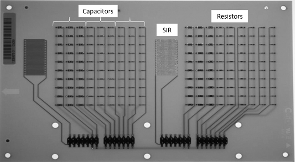
Test PCBA comprising of capacitors, resistors, and surface insulation resistance pattern
Preparation of test substrates with flux contamination
Three types of laminate and PCBA surfaces were prepared namely an as-received clean surface, and surfaces contaminated with non-activated flux residue (i.e. evaporated onto the PCBA surface at room temperature) and activated flux residue (i.e. evaporated on the PCBA surface at room temperature and then heated to a higher temperature consistent with the wave soldering process). The flux system studied was a ‘no-clean’ wave soldering flux meant for Pb-free soldering, and consisted of 80-90% of propan-2-ol, 5-15% ethanol, <2% of carboxylic acid, with an additional resin component. The flux residue contamination was achieved by spraying with a squeeze bottle, followed by drying at room temperature for 30 min. The amount of flux sprayed was approximately constant on all the laminate surfaces and was verified by the weight measurement after spraying to ensure that it is within the possible error limit. Activation of the flux was done by heating the PCBA to 255±5°C for 45 s (simulation of the wave soldering process temperature profile, peak temperature, and total time).
Preparation of coating on test substrates and exposure study
A conformal coating was applied on the laminate using a spin coater (WS-650SZ-s-6NPP-Lite Spin Processor, Laurell), by placing 4 mL of silicone polymer solution onto the laminate surface and rotating at 250 rev min−1. This process resulted in a coating thickness of approximately 100 to 110 μm after curing for 40 min at 120°C. The coated laminates were exposed to 60°C and 98% RH for 15 days and 25°C and 98% RH for 5 days test duration. After exposure, the morphology of the coated surfaces was analysed using a light optical microscope and the adhesion of the coating to the laminate was tested using the cross-cut tester.
The test PCBA on the other hand was coated by a dip coating method as the surface profile is not uniform, therefore it is difficult to get a uniform coating using the spin coater. The PCBA was dipped in the silicone polymer solution for 60 s as dwell time, thereafter lifted and held at vertical position for 60 s. The coating was then cured at 120°C for 40 min. The thickness of the coating achieved by this method on the surface of the components of each PCBA is approximately 30-40 μm. The conformal coated test PCBA was then exposed to 25°C and 98% RH for 60 h duration. Three replicates of laminate and PCBA test substrates were made for each sample in order to obtain fair reproducibility.
Adhesion testing by ‘cross-cut test’ ISO 2409
The adhesion strength of the coatings was tested using the standardised ‘cross-cut’ method. The test method is meant for assessing the resistance of coatings to lift off from the substrates when a right-angle lattice pattern is cut into the coating, reaching to the substrate. The cross-cut model 295/I was used for the test, which makes two sets of six cuts with spacing of 1 mm perpendicular to each other, resulting in a lattice of 25 small blocks. The cross-cut made on the coating is then analysed using the light optical microscope and evaluated on a scale ranging from 0 (very good adhesion) to 5 (poor adhesion). The amount of coating and the number of blocks removed is an indication of the adhesion.
Ion chromatographic analysis and conductivity of the flux residues
Analysis and quantification of the flux residue was done using a Dionex ICS-2000 ion chromatograph equipped with GP40 gradient pump, and a CD20 conductivity detector, an AS40 auto sampler and an EG40 eluent generator for anion detection. The eluent generator was used to generate KOH gradient concentrations. For the analytical separation, an IonPac AG11 (50×4 mm) guard column and an IonPac AS11-HC (250×4 mm) analytical column was used. Flux residues were extracted from the Test PCBA by allowing the residue to dissolve in water for 30 min. Mild brushing was done using a clean brush in order to remove the residues thoroughly. The extracted residue solution was fed into the AS40 automated sampler and analysed using the ICS-2000.
The conductance of the flux residue extracted in 200 mL of distilled water was measured using a CDM 210 conductivity metre (Radiometer Analytical SAS, Villeurbanne, France). The conductivity probe was calibrated using the 1M KCl solution prior to measurement and placed in the extracted solution. Conductivity was measured on three replicate samples in each case for better reproducibility.
Scanning electron microscopy
Surface morphology of the coating before and after exposure to humidity were analysed using a scanning electron microscopy (SEM, JEOL 5900 instrument), and chemical analysis of the corrosion products and other features were analysed using the EDX Spectroscopy attached to the SEM.
Results
Quantification of flux residue and conductivity of the extract
Quantification of the activator (carboxylic acid) content of the flux residue in the non-activated and activated state using ion chromatography is shown in Fig. 2. Two types of carboxylic acid activators were found in the flux type used for this investigation namely adipic and succinic acid. The non-activated flux residue consists of approximately 140 ppm of carboxylic acid content in total, however when the flux is activated, the total carboxylic acid content is reduced to approximately 35% (50 ppm) of the initial concentration.
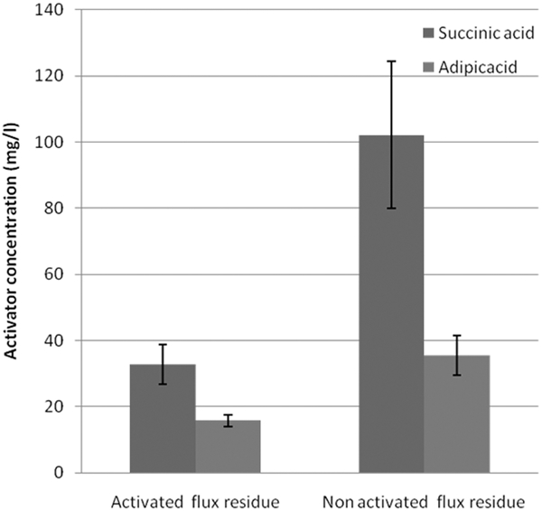
Amount of activators in the flux residue analysed using ion chromatography
The conductivity of the extracted flux solution is shown in Fig. 3. The conductivity of the extract from the clean PCBA is approximately ∼19 μS cm−1, while the PCBA containing the non-activated flux residue had the highest conductivity of ∼400 μS cm−1. The extract from PCBA with activated flux residues also exhibited higher conductivity (∼167 μS cm−1) than clean PCBA, but much less than the PCBA with non-activated residue.
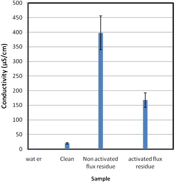
Conductivity of the extracted solution from the clean surface, and surface containing activated and non-activated flux residues
The amount of flux residue on the surface in terms of micrograms per square centimetre was measured by the weight gain method. It was found that the average amount of flux residue present at the surface was in the range of 20-70 μg cm−2, which, is in the range of allowable flux residues on class 2 and class 3 assemblies categorised by the standard IPC-TM-650.
Morphology of the coating
The morphology of the coating on the laminate after exposure to the test condition showed blisters on the surface where it was contaminated with flux residue. However, some of the blisters collapsed or disappeared when the samples were removed from the high humidity and kept outside for some time at ambient conditions. The blister formation for the non-activated flux residue is shown in Fig. 4a and the surface after 18 h in ambient conditions is shown Fig. 4b indicating that some of the blisters disappeared or collapsed.
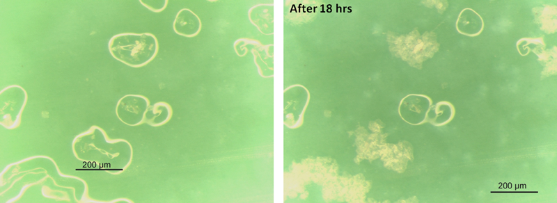
Blister formation on silicone coating a immediately after removal from the exposure to saturated humid condition, and b after 18 h on exposure to the humid condition
Adhesion strength of the coating on laminate
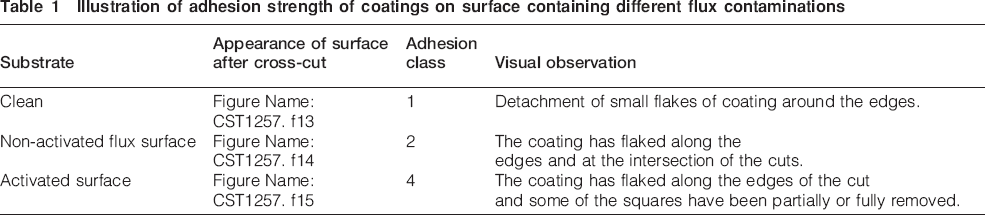
Table 1 shows the adhesion strength of the coating on the laminate after exposure to humidity using the cross-cut test. Results presented in the table shows that the adhesion strength of the coating was dependant on the cleanliness of the substrate. From the appearance after the cross-cut test, the coating on the clean laminate surface can be classified as class 1, while the coating on surface contaminated by the non-activated and activated flux was categorised as class 2 and class 4, respectively. The coating on the laminate with the activated flux residue showed severe detachment after the test.
Illustration of adhesion strength of coatings on surface containing different flux contaminations
Constant humidity test with 98% RH at 25°C
Typical leakage current curves from various channels of the PCBAs with and without flux residue contamination on the board during exposure to 98% RH at 25°C are shown in Fig. 5. Control samples without coatings are also included. Three PCBAs were tested in each case, but only a representative graph from each set of results is shown in Fig. 5. With no flux residue present on the surface, neither the uncoated boards, nor those that were conformal coated showed any indication of failure (Fig. 5a). The leakage current values are extremely low for the capacitors and the current values shown by the resistors are consistent with those expected to pass though the resistors at the potential bias applied. The leakage current across the SIR pattern was also found to be comparatively low.
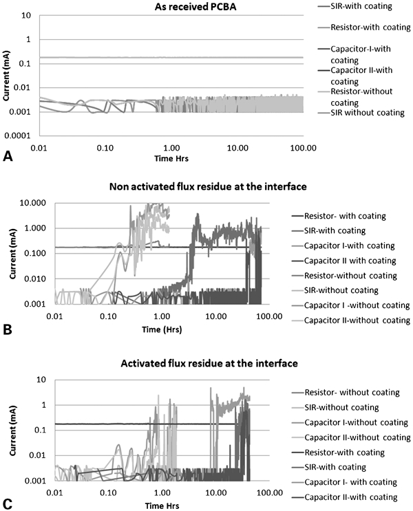
Electrical functionality of components measured as current leak for a as-received coated and uncoated PCBA, b PCBA containing non-activated flux residue, coated and uncoated, and c PCBA containing activated flux residue, coated and uncoated
However, the PCBAs that were contaminated with non-activated, Fig. 5b, or activated flux residue, Fig. 5c, showed, after an initiation period, a sudden increase in leakage current indicating that electrochemical migration (ECM) was present in all channels except for the resistors irrespective of with or without conformal coating. The time to first failure (TTF) (i.e. the time to show the first current peak) for different channels is summarised in Fig. 6. It is evident that in general the TTF values for all channels are higher for the conformal coated PCBAs. However it can be noted that, when the boards are contaminated with flux residues, the conformal coating has extended the failure time. Those boards without conformal coating, but with activated or non-activated flux residues showed failures within a comparatively short time (within 12-60 min) after exposure to high humidity. The boards with activated flux residue had a significantly longer TTF than boards contaminated with non-activated flux residue.
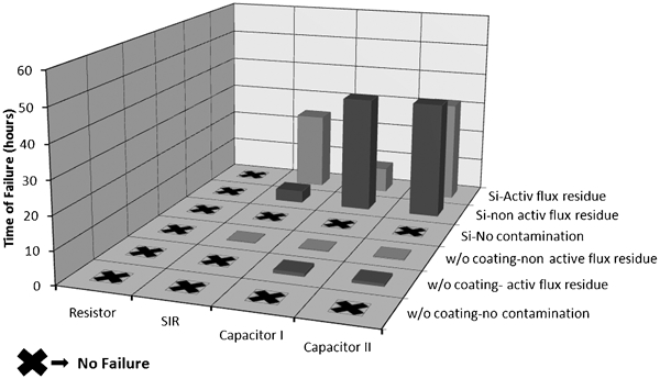
Time of failure of coated and uncoated components containing flux residue contaminations
For conformal coated PCBA, the TTF values did not show any correlation to type of flux residue, but in general the TTF increased significantly compared with uncoated and contaminated PCBA. No failure was found on the resistor part of the circuit irrespective of contamination or with or without coating.
Microscopic investigation on corrosion surface morphology
The morphology of SM capacitors observed under light microscopy after exposure to the test condition, with and without conformal coating is shown in Fig. 7. The capacitors from test PCBA without flux residues on the surface showed no signs of damage to the coating or corrosion on the metallic terminals (Fig. 7a and b). In the case of boards without conformal coating, the capacitors with non-activated flux residue on the surface have severe corrosion and ECM, Fig. 7c, compared to the capacitors on boards with activated flux residue, Fig. 7e. White residues were seen on the capacitors containing non-activated flux residue. The capacitors that are conformal coated with non-activated flux contaminant at the interface showed only severe corrosion, Fig. 7d, on the terminals, whereas the component without coating showed severe corrosion and ECM with dendrite formation across the terminals, Fig. 7c. In the case of activated flux residue on capacitors, both coated and uncoated components showed corrosion and ECM across the terminals, Fig. 7e and f. Since the coating is transparent to visible light, dendrites under the coating can be observed clearly. Total number of capacitors in the row that showed dendrites in the presence of activated and non-activated flux residue at the interface is shown in Fig. 8. The percentage of formation of dendrites on conformal coated capacitors that possessed activated flux residue at the interface is much higher (57%) than the percentage of dendrites formed on the capacitors with non-activated flux residues (8%) at the interface. The resistor component did not show any deterioration on the surface irrespective of the contamination present on the surface.
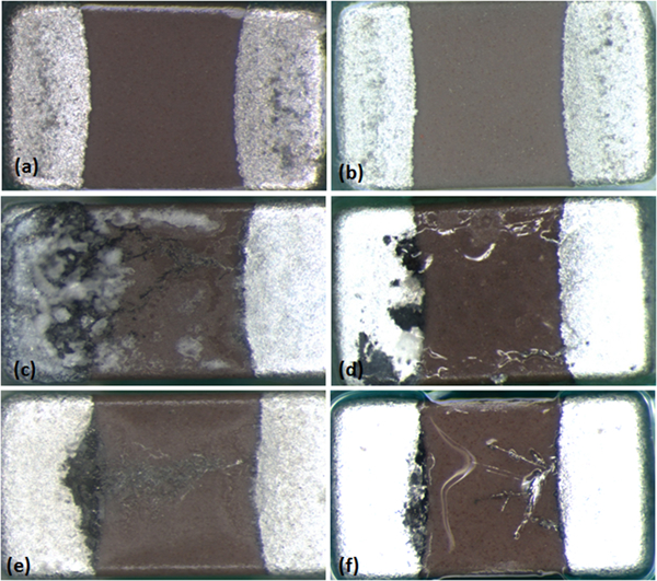
Typical surface morphology of chip capacitor on the test PCBA after testing (with and without conformal coating): a clean uncoated, b clean coated, c with non-activated flux residue and uncoated, d with non-activated flux residue and coated, e with activated flux residue and uncoated, and f with activated flux residue and coated
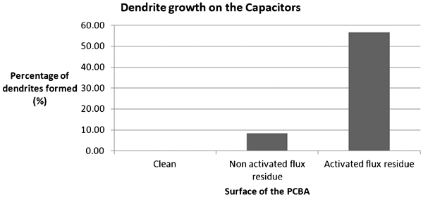
Percentage of capacitors undergone ECM failure under the conformal coating with and without flux residue contaminant on the surface
Chemical analysis of dendrites
An SEM picture of the surface morphology of the capacitor with non-activated flux residue at the surface after exposure to the test condition is shown in Fig. 9. Severe corrosion is evident at the anode side of capacitor in Fig. 9a and dendrites have formed from cathode to anode, Fig. 9b. The chemical composition of the dendrite, Fig. 9c, showed that it consists of a mixture of tin and tin oxides.
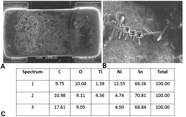
Morphological analysis of uncoated PCBA contained activated flux residue at the surface, after exposure to humid atmosphere a SEM image of chip capacitor showing severe corrosion and dendrite formation on the terminals, b high magnification image of a dendrite formed on the capacitor, and c energy dispersive X-ray analysis showing composition of the dendrite
The surface morphology of one of the failed capacitor that was conformally coated with flux residue after removal of the conformal coating is shown in Fig. 10a. Dendrites due to ECM have formed between the terminals below the coating, Fig. 10b, and EDX analysis of the composition of dendrite is shown in Fig. 10c.
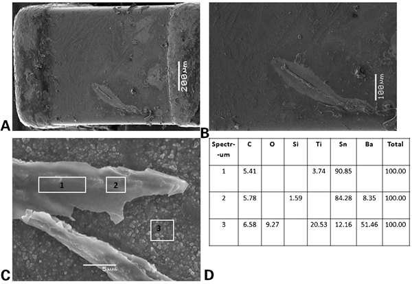
Morphological analysis of silicone-coated PCBA contained activated flux residue at the surface, after exposure to humid atmosphere a SEM image of chip capacitor after removal of the coating, showing dendrite formed across the terminals b High magnification image of the dendrite formed, and c energy dispersive X-ray result showing composition of dendrite formed on the capacitor
Chemical composition of dendrites analysed using EDX, without coating and in the presence of coating is compared in Fig. 11. Only Sn, O and Ni are included in the chemical composition while other elements such as Ti derived from the dielectric material used in the capacitor and C derived from sample preparation during mounting the specimen on SEM specimen stage were excluded in the EDX results shown here. Comparison of chemical composition showed significantly higher Sn:O ratio, Fig. 11, on dendrites formed under the coating compared to the composition of the dendrites formed without conformal coating indicating that the dendrites under the coating are mainly metallic tin with less precipitated tin hydroxide.
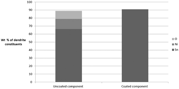
Weight percentage of dendrite constituents
Discussion
The present investigation clearly showed the degradation of the performance of silicone conformal coatings under exposure to humid environment when flux residue is present on the PCBA surface prior to the coating. A reduction in adhesion strength of the coating due to flux residues at the interface results in delamination together with permeation of moisture through the coating. This will create an occluded corrosive environment at the interface. The conductivity of the flux residue combined with moisture causes increase in leakage current on the board and corrosion of terminals of the components resulting in ECM under the conformal coated layer.
Polymer coatings act as a barrier between the environment and substrate providing physical isolation, chemical resistance, electrical insulation, and moisture protection. However, coatings are generally not completely impervious to corrosive reactants such as water, oxygen or other ions present in the atmosphere. The permeation of these reactants depends upon the chemical structure of the protective coatings. Coatings that have low permeability and moisture absorption are considered as efficient in protecting the substrate from corrosion to some extent. 11
Silicone is one of the widely used conformal coating to protect electronic boards from environmental influence and ensure high SIR. Various types of silicone conformal coatings like heat cured and room temperature vulcanised coatings are available for such application.2,4 The silicone coating studied in this paper is a solventless heat cured elastomer. Curing of such silicone polymers takes place by vinyl end blocked siloxane pre-polymer cross linking with methyl silane in the presence of a catalyst and heat. 12 In this type of curing no by products like water or volatile organic compounds are released. The main composition of silicone coatings are Si, O and organic groups attached to Si back bone. Since silicone polymers are an hybrid between organic and inorganic type of coatings, they combine the properties of both types. Apart from the intrinsic properties of the coating, performance of the coating is highly dependent on the cleanliness of the substrate. In the presence of ionic contaminations at the interface, when moisture is permeated through the coating, the adhesion of the coating to the substrate is affected and the presence of soluble ions at the interface, results in formation of blisters.
After the industry adoption of ‘no-clean’ flux technology, cleaning PCBAs before coating application is no longer done. However it has been found that the no-clean flux may affect the reliability of the boards in several ways.13–16 The no clean flux system mainly consists of three major components: (i) solvent (ii) activators, and (iii) vehicle. The activator component of the no-clean flux system is generally a mixture of one or two carboxylic acids.17,18 The amount of carboxylic acid present on the surface of the PCBA depends upon the amount of flux sprayed and the extent to which the sprayed flux is heated. The difference in the amount of carboxylic acid present in the activated and non-activated flux is clearly seen in Fig. 2. When the flux residues are present, they also decrease the SIR under humid conditions due to the conductivity of the ions present on the board (Fig. 3). The higher conductivity of the non-activated flux, compared to the activated flux, shows that when there is flux residue on the board, particularly where inadequate heating has occurred, serious SIR issues. It is important to note that the amount of flux residue present on the surface is still within the level specified for class 2 and class 3 assemblies according to the standard IPC-TM-650, although the limit is more for rosin types flux systems. This shows that even the allowable level flux residues on the boards could cause serious reliability issues on PCBA upon exposure to humid environment.
The electrical functionality of the test PCBA was also affected by no-clean flux residues when exposed to humid conditions as shown by the leakage current increase in Fig. 6. The combination of moisture with flux residues creates an electrolyte solution on the metallic terminals of the components and results in high leakage current which leads to corrosion and ECM across the terminals. When conformal coatings are formed on such contaminated surfaces, the adhesion strength of the coating to the interface is greatly reduced on exposure to a humid environment, Table 1. Silicone chemistry provides high permeation of moisture due to the weak intermolecular force between Si–O bonds in the polymer chain. 2 The diffusion coefficient of silicone coatings was estimated 19 as 4-7×10⁻¹¹ cm2 s−1 for non-volatile chlorides (e.g. NaCl) and 4-9×10⁻⁹ cm2 s−1 for volatile chloride (e.g. HCl) which is significantly higher than other coatings such as epoxies (approximately two orders of magnitude) or acrylics. Permeation of sulphur containing gases through the coating to the interface is a prime reliability concern for PCBAs used in agricultural environments, as severe corrosion failures were observed on silver surfaces caused by the sulphur species. 20
The carboxylic acids present in the flux residues are partially soluble in water and permeation of moisture through the coating results in accumulation of moisture in the occluded environment by dissolution of the residue. 17 The solute concentration at the interface results in blistering due to the continuous permeation of moisture through the coating and results in osmotic pressure between the substrate and coating, Fig. 4a. When the coated substrate is removed from high humidity and exposed to a lower humidity ambient, the blisters shrink as moisture is lost, Fig. 4b. Thus, there is large probability that the change is morphology of the coating due to moisture permeation at humid environment goes unnoticed during failure analysis of coated PCBAs carried out at ambient conditions. The adhesion of the coating after exposure to the humidity is reduced more for the specimen with activated flux residue (Table 1) compared to the one with non-activated flux residue. This might be attributed to the fact that for activated flux residue, carboxylic acid will be present as anhydride due to the heating process, which is highly hygroscopic.
In the case of PCBA coated with silicone, significant protection on components was observed on exposure to humid environment compared to uncoated PCBAs, however after an incubation time exposure, moisture still permeates through the coating which results in increase in leakage current, Fig. 5. The drastic increase in leakage current observed on components of the conformal coated PCBAs containing activated, Fig. 5b, and non-activated flux residue, Fig. 5c, compared to clean PCBA, Fig. 5a, clearly show the degradation of performance of the coating due to flux residue contaminations. The increase in leakage current was associated with severe corrosion and ECM across the terminals of the capacitors, Fig. 7.
There are numerous failure mechanisms that can contribute to the failure of the coating. Osmotic blistering is a major possibility where the surface flux residue attracts moisture through the coating to equalise the local water activity. Alkalinity at the interface as a result of corrosion can also cause cathodic delamination or cathodic blistering. Electro-osmosis is a further mechanism, where water is absorbed by the coating due to potential difference present on the substrate.21,22
Silicone coatings are known for high permeability of water vapour and other volatile gases. 23 Nevertheless silicone is considered as a good encapsulating material due to its direct bonding to the surface by eliminating water, therefore, moisture permeating through the coating has no place to get adsorbed at the interface. Hence it was found that silicone encapsulation systems can protect integrated circuits on ceramic substrates even under aggressive test conditions such as thermal shock by rapid transfer from ice water to boiling water for five cycles and exposure to pressurised steam at 150°C, 55 lb in−2 for 4 h. 24 No leakage current was observed in the silicone encapsulated module, but other coatings like polyimide showed high leakage current. However this condition is true only if the substrate is completely clean. It has been reported that silicone polymers while considered as highly protective for liquid water, have water vapour permeation rates some 100-1000 times than hydrocarbon-based polymers. 25 Upon exposure to moisture, corrosion can take place on various places of the board such as on solder pads, terminals of the components, solder alloys, conducting lines etc., however the probability for corrosion at the terminals of the components is much higher and faster, due to the contours present in a component and lesser thickness of the coating at the edges, and easier penetration of moisture.
Even though there is no significant difference between activated and non-activated flux residue on influencing the corrosion reliability of circuit boards, Fig. 6, it is interesting to note from Fig. 8 that the boards with activated flux residue showed typical dendrite formation whereas in the case of boards that contained non-activated flux residue showed only corrosion on the terminals of the capacitors and damage to the coating was evident. This may be due to the change in stability of the dissolved tin species depending on the amount of carboxylic acid at the interface and the occluded pH conditions. As explained by Minzari et al. 26 ECM of tin on open surfaces takes place by a mechanism involving alkaline plating on Sn, which needs stannate ions to be stable close to the cathode. Stannate stability as close to the negative electrode as Minzari et al. 26 explained depends on the strength of alkaline conditions created locally due to the cathodic reactions. However, in the presence of flux residue, due to the presence of carboxylic acid, a reduction in pH could be expected, which will be more significant for the specimen with non-activated flux residue as it contain higher amounts of carboxylic acids. Reduction in alkaline pH causes precipitation of Sn as tin hydroxide rather than depositing in the form of dendrites. Another possibility is the inhibiting nature of carboxylic acids on corrosion of tin.27,28
The dendrites formed under the coating appeared to be more metallic compared to the dendrites observed for the uncoated PCBA surfaces. On uncoated PCBA surfaces, dendrites mixed with hydroxides have been observed in this work and others.26,29,30 This difference in composition of the dendrite might be due to the difference in the chemistry of the occluded solution compared to the local chemistry under open conditions. However, more work is needed to exactly understand the operating mechanisms of dendrite formation with flux residues under the coating.
It is significant that none of the resistors showed ECM failures with or without coating or with contamination. This is suspected to be due to the difference in the surface features of a resistor compared to a capacitor. Resistors have a glass protection layer on the surface, which might make it difficult for the water layer formation compared to the rough surface of the capacitor (due to the ceramic layer). However, no clear explanation is presently found to this effect, although similar behaviour for resistors was found in a number of investigations with and without coating. In general, the electronic industry also reports fewer corrosion failure issues related to chip resistors.
Conclusion
Significant levels of flux residue containing carboxylic acids were present on the laminate or PCBA surface even after activation at lead-free soldering temperature.
The presence of flux residues used in this investigation reduces the SIR by increasing the conductivity of water layer. The non-activated flux residue increases the conductivity more than twice than activated flux residue due to the presence of higher levels of carboxylic acids.
When there is no flux residue contamination at the surface, the electrical performance of the components was unaffected on exposure to a humid environment.
In the presence of flux residues the electrical performance of components was affected due to severe corrosion on the terminals and also ECM on exposure to saturated humid environment irrespective of whether the flux residues were activated or non-activated.
When the PCBA was conformal coated, the coating provided some limited protection from the humid environment, however, after an incubation period a drastic increase in leakage current across the components, and resulting failure, was observed in the presence of flux residues.
Adhesion of the coating was reduced due to flux residue irrespective of whether it was activated or non-activated. However, the effect was greater for substrates with activated flux residue.
Components on the test PCBA with activated flux residue under the conformal coating showed a higher probability of dendrite formation, while the component containing non-activated flux residue showed severe corrosion damage with less probability for dendrites formation.