
Abstract
TiC–Cr7C3–CNTs cermet coating on 304 stainless steel substrate was prepared using a newly developed in situ technology consisting of self-propagation high-temperature synthesis reaction, laser cladding and metal dusting techniques. The samples were subjected to various microstructure examinations and their corrosion behaviour was compared with that of 304SS in 1 mol L− 1 HCl solution. The results showed that high quality of the coating was obtained. Many reinforcements were more or less uniformly distributed within the grain and grain boundary in the microstructure. Carbon nanotubes (CNTs) were obviously observed, but the length of CNTs was shorter after laser cladding. Compared with the 304SS substrate, the coating has no pitting and maintained a low corrosion rate in 1 mol L− 1 HCl solution.
Introduction
Carbon nanotubes (CNTs) have long been considered to be an ideal reinforcement for ceramic and metal matrix composite coatings using various fabrication routes due to their high strength and light weight properties and also due to their favourable geometrical properties such as high aspect ratio, high specific surface area and excellent mechanical properties.1–3 Although different production techniques have been successfully applied to incorporate CNTs to metal and ceramic composite coatings, obtaining a uniform distribution and strong interfacial bonding are still a challenge even though a great deal of research has aimed at addressing this issue.4–9 Laser cladding is an effective way to obtain a uniform dispersion of CNTs in the composite coating because uniformly dispersed CNTs in the coating can develop as a result of the violent stirring and convection driven by thermocapillarity in the laser molten pool.10,11 The unique advantage of using laser cladding is its ability to create the possibility of a uniform dispersion of CNTs.
Metal dusting (MD) as a high-temperature corrosion has lately been considered as a method for producing CNTs, because a fresh catalyst is provided continuously during this process. 12 Type 304 stainless steel (304SS) is extremely susceptible to MD. 13 The in situ growth of CNTs on the surface of 304SS during the MD process provides the uniform CNT layer on the 304SS surface.
Inspired by the possibility of laser cladding in obtaining a uniform dispersion of CNTs in the composite coating together with the uniform CNT layer on the surface of 304SS by MD process, the authors report herein the use of laser cladding and MD methods to fabricate uniform CNT-reinforced cermet coating on the 304SS substrate.
In the present study, the first step is to modify the 304SS surface by the MD process obtaining a uniform CNT layer on the 304SS surface as the steel substrate, followed by laser cladding of the 304SS substrate. Ti powders through powder injection can be remelted by adjusting the focus point of the laser beam before it reached the substrate surface, and then the laser molten pool containing Ti will form on the surface of the CNT layer on the 304SS substrate. The self-propagation high-temperature synthesis (SHS) reaction between Ti and CNTs soon occurred in the laser molten pool on the substrate surface, producing TiC particles that may lead to numerous positive advancements in the coating.14–17 Meanwhile, the Ti element in the laser molten pool can improve the wettability of CNTs and the surrounding matrix, resulting in the effective interfacial load transfer. 18 Additionally, the role of stirring and convection was further increased in the laser molten pool due to the SHS exothermic reaction. Finally, TiC particles and the unreacted CNTs with strong interfacial bonding are uniformly dispersed in the coating due to the violent stirring and convection in the laser molten pool.
Corrosion and abrasion are the two most significant reasons of degradation in industrial parts. Hence, extensive research studies have been conducted in order to develop the methods of reducing corrosion and wear costs. It is well known that wear resistance of the composite coatings was improved due to the addition of ceramic particles or CNT reinforcements, while the influence of reinforcement addition to the coating on corrosion behaviour has been reported with different results by different groups. The corrosion resistance of ceramic particle (CNT) reinforced matrix metal composites was deteriorated by addition of ceramic particles (such as TiC particles 19 and SiC particles 20 ) and CNTs7,21 due to the serious galvanic corrosion and cathodic activity. Conversely, the corrosion resistance was found to improve with addition of garnet in Al alloy, 22 TiC in 304 stainless steel 16 and CNTs in Mg alloy. 23 These results showed that many factors influenced the corrosion resistance of ceramic particle (CNT) reinforced matrix metal composites, such as the preparation technique, distribution of reinforcements, etc. To date, few references could be found concerning the corrosion behaviour of CNT-reinforced cermet coating, especially a novel method to produce CNT-reinforced cermet coating in the present study.
A newly developed in situ technology, consisting of traditional SHS reaction, laser cladding and MD techniques, was used to produce CNT-reinforced cermet coating on the 304SS substrate. In the present study, a detailed investigation has been undertaken to make clear the formation mechanism and characterisation of the coating. A corrosion process and a relevant corrosion mechanism are proposed based on the experimental results and theoretical analyses.
Experimental procedures
Materials and MD
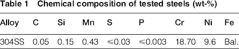
The 304 austenitic stainless steel, with dimensions of 50 mm × 50 mm × 8 mm and chemical composition shown in Table 1, was used. The specimen surface and edge were mechanically ground, finishing with a 600-grit emery paper, followed by ultrasonic cleaning in distilled water and then in acetone. An MD test was conducted in a flowing 68CO–31H2–1H2O (a C = 19.0, P O2 = 5.4 × 10− 25 atm) mixed gas through a quartz tube at 680°C for 20 h. The gas flow rate was fixed at 100 mL min− 1, and the pressure in the reaction chamber was 1 atm. Figure 1a shows the scanning electron microscopy (SEM) image of the deposit formed on the surface of 304SS, exhibiting the uniform, fluffy CNT layer. The microstructure of CNTs was further characterised by transmission electron microscopy (TEM), as shown in Fig. 1b. It is found that the sample surface was covered with CNTs with an average diameter of ∼50 nm and a length of typically a few micrometres. Each CNT had an encapsulated particle at its tip, consisting of Fe and Ni. The formation of Fe/Ni metallic particles, almost free of Cr, was due to the MD reaction, as reported previously. 13 These freshly formed Fe/Ni particles further catalysed the decomposition of CO and assisted CNTs. 24
Chemical composition of tested steels (wt-%)
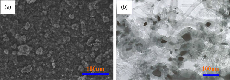
a SEM image; b TEM image
The samples were weighed initially and placed in the reactor. After reaction, samples were weighed immediately. The extraction and weighing were performed with great accuracy in order to avoid touching the samples directly and getting them polluted. Weight gain after reaction represented the total carbon uptake in the form of CNT deposition and metal carburisation. In the present study, weight gain of the total carbon uptake can be considered as weight of CNTs. A pre-placed powder was composed of 50 wt-%Ni and 50 wt-%(Ti and CNTs) with the mole ratio of CNTs and Ti corresponding to 1.1. The purpose of Ni addition is to restrain the intensity of the SHS reaction between Ti and CNTs in the laser molten pool. A pre-placed powder of Ni and Ti was dry mixed for 2 h in a ball mill.
Cladding system setup and deposition parameters
Laser cladding was carried out using an indigenously developed 5 kW continuous wave CO2 laser system. Laser surface treatment included scanning the CNT layer on the 304SS surface with the laser beam of 3.0 kW power at the rate of 1.0 mm s− 1 and the rectangular beam spot (6 mm × 1.5 mm). Before the deposition experiment, the Ni and Ti metal powder was delivered into the laser processing zone using a lateral powder feeder, with the aid of a compressed air jet. The feed angle between the substrate and the powder feeder nozzle was 60°. In the experiment, the focus point of the laser beam was adjusted to a position slightly above the substrate surface so as to melt the Ni and Ti metal powder before it reached the surface. This arrangement was necessary because liquid metal can provide protection to CNTs and minimize CNT damage from the laser beam during the laser cladding process. The laser apparatus employed for the tests is shown in Fig. 2. The laser tracks were overlapped at 17% track width to achieve surfacing. Hence, the entire laser surface on the 304SS substrate can be obtained with an overlapping rate of ∼17% between two adjacent laser tracks.
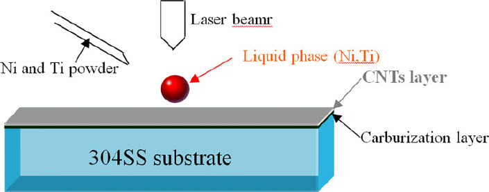
Schematic view of laser cladding test
Clad characterisation and immersion tests
Microstructural evaluations were carried out by optical microscopy, X-ray diffraction (XRD), SEM and TEM with energy-dispersive X-ray spectroscopy (EDX).
The specimens were machined and embedded in epoxy resin, leaving a rectangular working area of 1 cm2. Before the experiments, the surfaces of the specimens were ground with silicon carbide (SiC) papers progressively up to 600 grit, rinsed with distilled water and then degreased in acetone. The immersion tests were carried out by suspending the samples in a still solution of 1 mol L− 1 HCl in deionised water exposed to atmospheric air. The specimens were exposed to the test solution for 60 days. The 304SS substrate was used for comparison.
Polarisation measurements
The working cell was a standard three-electrode cell having a Pt net as a counter electrode and a saturated calomel electrode (SCE) as a reference electrode. All the measured potentials presented in the paper were referred to this electrode in 1 mol L− 1 HCl solution. Before potentiodynamic polarisation measurements, the open circuit potential (OCP) was monitored for 1°h to ensure a stable electrochemical condition. The polarisation curve's sweeping rate was 2 mV s− 1, with a scanning range from − 0.5 to +1.0 VSCE of OCP.
Electrochemical impedance spectroscopy
For electrochemical impedance spectroscopy measurements, the samples were exposed to 1 mol L− 1 HCl solution for 60 days. Electrochemical impedance spectroscopy measurements were performed at OCP from 10− 2 to 104 Hz with an amplitude of 10 mVSCE, using the same three-electrode cell as in the section on ‘Polarization measurements’. The equivalent circuit simulation program ZsimpWin was used for data analysis, synthesis of the equivalent circuit and fitting of the experimental data.
Results and discussion
Microstructure
Figure 3 shows the X-ray spectra of the coating. In addition to the γ-(Fe, Ni) phase, TiO2, TiC and Cr7C3 were identified in the coating. During the melting and solidifying process of the coating, the substrate (Fe and Ni elements) and pre-placed Ni powder formed γ-(Ni, Fe) solid solution according to the Fe–Ni binary phase diagram, which is in agreement with the XRD results. 25
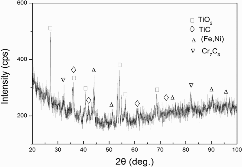
X-ray diffraction pattern of coating
The SEM micrograph of typical cross-sections of this coating is shown in Fig. 4a, and their high magnification SEM images are shown in Fig. 4b–d. It can be seen that a continuous, dense and adherent laser-clad coating was formed on the 304SS substrate. It is worth noting that the damaged areas with dark contrast were also observed on the top of the coating. Many particles were more or less uniformly distributed within the grain and grain boundary in the microstructure (see Fig. 4b and c). Microanalysis has been performed on these particles, and the results reveal that one is Ti-rich carbide and the other is Cr-rich carbide, as shown in Fig. 4f and g. Thus, it can be deduced that the particles are TiC and Cr7C3 phases by the EDX and XRD results. Backscattered electron imaging has been further performed on these particles, and the results reveal that most of the particles are TiC and others are Cr7C3, corresponding to the red arrows in Fig. 4e. The damaged areas on the top of the coating are composed of two types of particles, one is TiC with dark contrast and the other is TiO2 with relatively light contrast (see Fig. 4d and h). In addition, a large number of porosities were seen in the damaged areas.
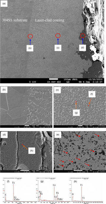
a cross-section of whole coating; b–d corresponding high magnification of a; e backscattered electron image; f–h corresponding EDS in c and d.
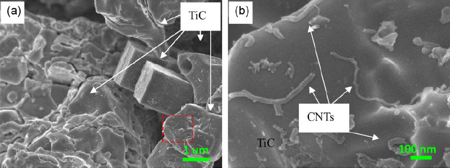
Details of the microstructure of the coating were further examined by TEM, as shown in Fig. 5. In addition to the tiny particles, many rod-shaped reinforcements were observed in Fig. 5. Composition analysis by EDX showed that the tiny particles and rod-shaped reinforcements were all TiC. The results point towards co-existence of both particles (in micrometres and nanometres) and rod-shaped TiC within the coating. Unfortunately, CNTs were not observed in SEM and TEM images. In order to observe CNT in the coating, the ceramic phases and CNT with high chemical stability in the coating were extracted with 95 vol.-%CH3OH and 5 vol.-%HCl below 0°C through electroextraction. Subsequently, the products in raffinate were collected and dried. Characterisation of product phases extracted from the coating was carried out using SEM. Carbon nanotubes were obviously observed in Fig. 6, and the length of CNTs was shorter after laser cladding, which has also been reported in the previous literature. 26
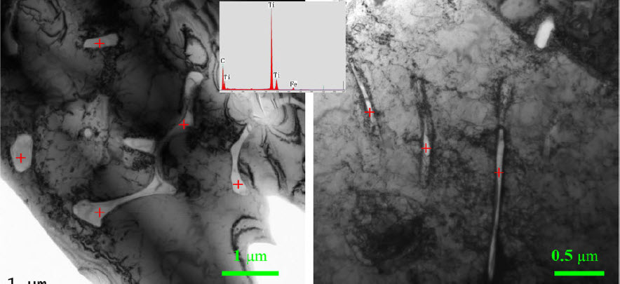
Bright field image (TEM) of coating
a low magnification; b high magnification
Before the laser beam reached the substrate, it focused on the Ni and Ti metal powder from the powder feeder that could absorb the laser energy, and the residual laser energy melted the metal powder, producing the liquid phase (Ni, Ti). When the liquid phase (Ni, Ti) reached the CNT layer on the 304SS surface, the thermal energy in the liquid phase (Ni, Ti) was simultaneously absorbed by the CNT layer and the 304SS substrate; the SHS reaction would be triggered between liquid Ti and CNTs, and then the molten pool on the 304SS surface was easily formed. This means that the carburisation layer would be molten due to the formation of the molten pool on the surface of the 304SS substrate. As a result, the melted alloy elements could diffuse each other between the coating and the substrate, which contributed to produce good metallurgical bonding between the coating and the substrate; the addition of Ni caused the formation of a large amount of γ-(Fe, Ni) in the coating. In addition, it is inevitable that the Cr element from the 304SS substrate also reacted with CNTs in the molten pool, producing Cr7C3 reinforcement. Therefore, the cermet coating on the 304SS substrate, consisting of γ-(Fe, Ni) as a metallic matrix binder and TiC, Cr7C3 and unreacted CNTs as reinforced phases distributed uniformly in the microstructure, has been obtained by SHS reaction, laser cladding and MD techniques. The formation of rod-shaped TiC is possibly attributed to the shape of the CNT; however, the origin of this phenomenon is not clear at this stage and needs further research.
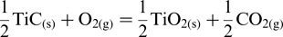
In this case, no protective gas was supplied during laser cladding, resulting in the occurrence of oxidation on the surface of the laser molten pool. The reaction between TiC and oxygen is expected to occur to produce TiO2 and CO2 at the interface between the molten pool and air according to reaction (1)

Electrochemical tests
The potentiodynamic polarisation behaviour of the 304SS substrate and the coating after removing the TiC–TiO2 ceramic layer using electric tools in 1 mol L− 1 HCl solution is given in Fig. 7. Their E corr, βa, βc and i corr values are summarised in Table 2. It can be seen from Fig. 7 that the passivation behaviour of 304SS was obviously observed, and the coating showed no signs of the passivation behaviour. As compared to 304SS, E corr values had shifted to a more positive region along with a remarkable decrease in i corr values indicating a lower corrosion rate for the coating.
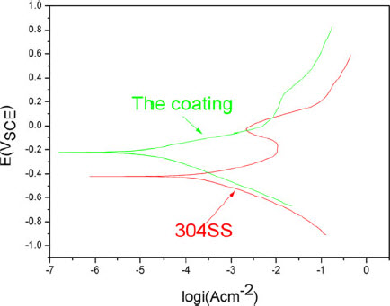
Polarisation curves of studied alloys exposed to 1 mol L− 1 HCl solution (potential scanning rate: 2 mV s− 1)
Ecorr, βa, βc and icorr values of coating and 304SS samples derived from polarisation curves after 60 days of exposure to 1 mol L− 1 HCl
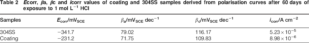
Figure 8 shows the typical Nyquist plots of the 304SS substrate and the coating samples exposed to 1 mol L− 1 HCl solution for 60 days. The distance along the real axis where the loop of the coating appears is longer than that of the corresponding 304SS substrate, which indicates that the coating has the highest charge transfer resistance. The Bode plots of the 304SS substrate and the coating were further obtained in this case. From Fig. 8a, it can be seen that the values of the charge transfer resistance, corresponding to the corrosion resistance, were R 304SS < R coating. From the Bode plots (Fig. 8b), there was no distinct diversification of impedance modulus, and the change in impedance modulus was similar to the charge transfer resistance. Two peaks in Fig. 8c for all samples were obviously observed, which indicate two time constants in its equivalent circuit.
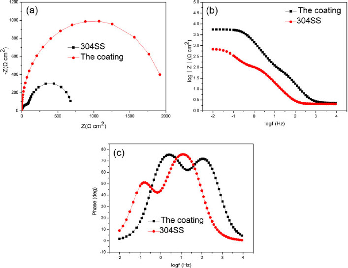
a Nyquist plots; b impedance modulus; c phase angle
Impedance spectra can be modelled as electric equivalent circuits given in Fig. 9. These are simple circuits for the corrosion system under charge transfer control, where no mass transport was detected. A constant phase element (CPE) was introduced to represent the double layer capacitance due to its non-ideal behaviour. The impedance of a CPE can be expressed as Z CPE = [A(jω)]− 1, where ω is the frequency, A is the CPE magnitude and the exponent α is between 0 and 1.
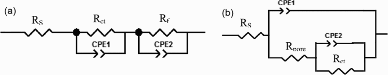
Equivalent circuits for a coating and b 304SS in 1 mol L− 1 HCl
The impedance data for the coating correspond well to the model shown in Fig. 9a. Corrosion products were formed on the surface of the coating in 1 mol L− 1 HCl solution in the current study and then were discussed in the later part. The high frequency loop can be attributed to the double layer formed at the interface between the coating surface and the electrolyte, while the low frequency loop was related to the corrosion products formed on the coating surface, i.e. to the diffusion of ions through the corrosion product layer. 27 In Fig. 9a, R S is the solution resistance, CPE1 is the capacitance of the double layer, R ct is related to the charge transfer resistance, and CPE2 and R f are the capacitance and resistance of the corrosion products respectively.
The equivalent circuit of the 304SS substrate was shown in Fig. 9b and could be explained using the model of the Cr-rich passive layer with defects. The high frequency loop can be attributed to the resistance and capacitance of the corrosion process at the 304SS/electrolyte interface that results from the exposure of the Cr-rich passive layer to the electrolyte due to the presence of pores. The low frequency loop can be attributed to the Cr-rich passive layer. In Fig. 9b, R S is the solution resistance, and CPE1 represents the capacitance of the Cr-rich passive layer. R pore is the resistance of charge transfer inside the pores; CPE2 and R ct are the capacitance and resistance of the corrosion process that occurred at the interface between 304SS and the solution at the bottom of the pores.
Surface morphology
In order to have a deeper insight into the reason for the significant difference in the corrosion stability of the studied samples, all kinds of surface morphologies were taken. Details of corrosion scale morphologies are examined using SEM, as shown in Fig. 10a and b. Many corrosion pits were clearly observed in 304SS (Fig. 10b), whereas in the coating, there was a continuous corrosion scale and no pits were observed, indicating that no or few defects were formed in the coating using laser cladding (Fig. 10a).
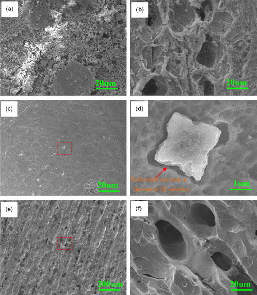
a–b coating and 304SS before removing corrosion product scale; c–d coating after removing corrosion product scale;
In order to obtain further insight into the corrosion mechanism, the surface morphologies of the studied samples after removing the corrosion product scale are characterised by SEM (Fig. 10c–f). Many large corrosion pits were clearly observed in 304SS (Fig. 10e and f), whereas in the coating, there was no pitting but the interfacial crevices around the TiC particles were obviously observed (Fig. 10c and d), suggesting that preferential corrosion has possibly occurred at the steel matrix/TiC interface. For the coating, preferential dissolution of the matrix around the particles led to TiC particle dropout. Figure 11 presents cross-sections of the corroded specimens of all samples after exposure to 1 mol L− 1 HCl solution for 60 days. Extensive pit formation occurred on the surface and had penetrated into the substrate for 304SS, while it disappeared in the coating.
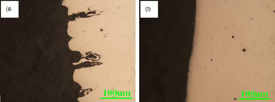
a 304SS; b coating
The residual stress in the coating was induced in the course of laser cladding due to the difference in mechanical and thermal properties of the different phases (matrix and reinforcement in the coating) during rapid solidification.28–30 Especially, inhomogeneous distribution of reinforcements in the coating is an important factor influencing residual stress concentration. If the stress concentration was higher than the strength of the coating, a crack originated and propagated in the coatings. At present, high cracking susceptibility of the hardfacing coatings using laser cladding limits its application. 31 The reason that cracks were not found in the coating in this case was given as follows: (i) TiC, Cr7C3 and CNT reinforcements are distributed uniformly in the coatings by laser cladding, and the microstresses were decreased markedly. (ii) The surface of the molten pool was covered by the TiC–TiO2 ceramic layer as the molten slag during laser cladding, and the temperature gradient could be reduced, contributing to the decrease in the crack sensitivity of the coatings. (iii) Rod-shaped TiC (see Fig. 5) and CNT reinforcements are considered as strengthening the matrix more effectively than particle reinforcements do owing to the resultant shorter inter-reinforcement spacing, namely, high strength of the coating can be obtained in this case. Therefore, the relatively better corrosion resistance of the coating compared with 304SS is related to the high quality of the coating in the present study.
In addition, this may also be partly due to more excellent corrosion resistance of TiC, Cr7C3 and CNT phases and the γ-(Fe, Ni) binder in the coating. Meanwhile, the improvement obtained after laser treatment could also be due to homogenisation and refinement of the microstructure resulting from the non-equilibrium rapid solidification process, elimination of pores and the achievement of a good metallurgical bond at the coating/substrate interface. 32
It has been known that pitting corrosion in stainless steels in solutions containing Cl− is considered to be a prevailing phenomenon and undesirable because it may result in local failure and an uncertain corrosion rate.33,34 However, in the coating, a galvanic corrosion cell may form between reinforcements (TiC, Cr7C3 and CNTs) and the γ-(Fe, Ni) matrix. As immersion time increased, the galvanic corrosion developed and became significant enough to result in disbanding of reinforcements from the matrix (see Fig. 10c and d). Apart from microgalvanic corrosion, the presence of reinforcements increases the defects of the passive film, resulting in the increasing number of pit nucleation sites and the decreasing ability to self-healing of the passive film. As time goes on and the pits grow, they will become connected, forming a corroded surface. General corrosion can be achieved as all metals beneath are in the same corrosion product covered condition. Introducing a widespread secondary phase intermetallic network is a possible way to achieve this ideal general corrosion process. Clearly, although reinforcements (TiC, Cr7C3 and CNTs) have adverse effects on the overall corrosion resistance, they can inhibit the pitting corrosion of the coating to some extent.
Conclusions
TiC–Cr7C3–CNTs cermet coating on the surface of 304SS has been prepared using a novel method consisting of SHS reaction, laser cladding and MD techniques. A continuous, dense and adherent laser-clad coating was formed on the steel substrate. The microstructure consisted of a γ-(Fe, Ni) base binder and reinforcements (TiC, Cr7C3 and CNTs) distributed uniformly in the microstructure.
Many reinforcements were more or less uniformly distributed within the grain and grain boundary in the microstructure. Carbon nanotubes were obviously observed and the length of CNTs was shorter after laser cladding. As compared to 304SS, E corr values had shifted to a more positive region along with a remarkable decrease in i corr values indicating a lower corrosion rate for the coating. Meanwhile, the severe pitting corrosion that was observed in 304SS did not exist for the coating. Although reinforcements (TiC, Cr7C3 and CNTs) have adverse effects on the overall corrosion resistance, they can inhibit the pitting corrosion of the coating to some extent.
Footnotes
Acknowledgements
This research was supported by the National Natural Science Foundation of China (no. 51202143), the Shanghai Education Innovation Project (no. 14YZ108), the 973 Program (2014CB643306) and the Doctoral Program of the Ministry of Education (20113121110001).