
Abstract
A Cr(III) contained conversion coating on AA2024-T3 was prepared in solution containing Cr2(SO4)3 and K2ZrF6. Its composition was analysed using X-ray photoelectron spectroscopy, and its corrosion resistance was characterised by electrochemical measurements and neutral salt spray exposure. To investigate its self-repairing effect, the coupling current between a small uncoated sample and a large coated sample was monitored through an artificial scratch cell. The coating mainly consists of zirconium oxide and chromium oxide and hydroxide; no Cr(VI) species is detected. It improves the corrosion resistance by hindering the anodic process as well as the cathodic process. Meanwhile, it possesses self-repairing effect, which is generated from the release of Cr(III) species from the coating, migration and then deposition on the nearby scratch area.
Keywords
Introduction
AA 2024-T3 is widely used in the aircraft industry due to its high specific strength, good fracture toughness and low cost. The addition of alloying elements such as Cu, Mg and Mn provides superior mechanical properties, but also leads to the formation of intermetallic particles that make the alloy susceptible to localised corrosion, especially pitting corrosion and intergranular corrosion.1,2
The conversion coating on the substrate surface refers to a surface that will more easily accept subsequent coating or provide for a more corrosion resistant surface. 3 Chemical conversion coatings are one of the most effective and most widely used pretreatment processes for protecting Al alloy. Chromate [Cr(VI)] conversion coatings have long been employed in the surface passivating process for Al alloys. However, due to the toxic and carcinogenic effects of hexavalent chromium [Cr(VI)] compounds, their use has been banned by legislations in many countries.4,5
In recent years, researchers developed a variety of chemical conversion coatings, including Ti, Zr and Mo metal salt conversion coatings.6–12 The rare earth conversion coatings for Al alloys have been widely studied.13–15 However, none is as effective as the Cr(VI) conversion coating.
A promising replacement for the Cr(VI) conversion coatings is the trivalent chromium [Cr(III)] conversion coating. The Cr(III) conversion coating is currently one of the leading non-chromate and environmentally friendly conversion coatings, as it has been shown to provide excellent corrosion protection and paint adhesion. 16 It was first developed by Agarwala and colleagues, who obtained corrosion resistant coatings on aluminium alloys by immersion in aqueous solutions containing Cr2(SO4)3 and Na2SiF6 or NaF.17,18 Now, some patents were reported to introduce the Cr(III) conversion coatings.19–21 In addition, it was found that the Cr(III) conversion coating post-treated in H2O2 possessed self-repairing effect, due to Cr(VI) introduced in to the coating by the H2O2 treatment. To study the self-repairing behaviour and mechanism of the Cr(VI) conversion coating, Frankel et al. established an artificial scratch cell. 22 Recently, they used this artificial scratch cell to investigate the Cr(III) conversion coating system and found that the Cr(III) conversion coating on AA2024-T3 also possessed self-repairing effect. 23
In this paper, a Cr(III) contained conversion coating on AA2024-T3 was prepared in conversion bath containing Cr2(SO4)3 and K2ZrF6, and its corrosion resistance was characterised. Meanwhile, its self-repairing behaviour was investigated by coupling current measurement in a designed artificial scratch cell.
Experimental
Materials preparation
The industrial AA2024-T3 alloy sheet with a thickness of 3 mm was used as substrate material. The alloy samples were polished subsequently with 400#, 800#, 1000# and 1200# abrasive paper, degreased with acetone for 10 min, activated by immersion in 5%NaOH aqueous solution for 2 min and pickled in 20% nitric acid solution for 30 s before execute the conversion process. Samples were rinsed with distilled water after every procedure. According to the published patents19,21 and our previous study, the Cr(III) contained conversion coating in this case was formed in the conversion bath containing 5 g L− 1 chromium sulphate [Cr2(SO4)3] and 2 g L− 1 potassium fluozirconate (K2ZrF6) at 40°C. The pH value of the conversion solution was adjusted to 4 before the conversion treatment, and the conversion time was 10 min. After finishing the conversion process, all the coatings were rinsed with distilled water and dried in air at room temperature.
Characterisation of conversion coating
The coating morphology was observed by a scanning electron microscope (SEM, Quanta-200, FEI). The X-ray photoelectron spectroscopy (XPS, K-Alpha 1063, Thermo Fisher Scientific, UK) was used to investigate the coating composition. The XPS with a monochromatic Al K α resource was operated at 72 W. The typical operating vacuum degree was ∼10− 9 mBar.
Electrochemical measurements and salt spray exposure were used to investigate the corrosion resistance of the conversion coatings. The electrochemical experiments were performed using an Electrochemical Workstation (CHI660B, Chenhua, Shanghai, China). A three-electrode cell was used. A saturated calomel electrode (SCE) and a platinum foil were served as the reference electrode and counter reference electrode respectively. The polarisation curves and electrochemical impedance spectroscopy (EIS) were measured in neutral 3.5%NaCl solution. Measurements of polarisation curves were carried out at a scan rate of 2 mv s− 1. Electrochemical impedance spectroscopy was measured with the perturbation of 5 mV in frequency range from 100 kHz to 0.01 Hz. Salt spray exposure was carried out by placing coated and uncoated samples with a dimension of 100 mm × 65 mm × 2 mm into a chamber containing 5%NaCl salt fog at a controlled temperature of 35°C in accordance with ASTM B 117 specifications.
Experiments for self-repairing study
Based on the artificial scratch cell of Frankel et al.,22,23 a modified artificial scratch cell was designed to study the self-repairing effect of the conversion coating. The schematic diagram of the artificial scratch cell is shown in Fig. 1. A small uncoated sample (simulating the scratch area) with a diameter of 3 mm was inserted in the centre hole of a bottom large coated sample. These two samples were insulated by resin and used as two working electrodes. In addition, wires were connected on the back of each working electrode. The small uncoated sample and the large coated sample were named as working electrode 1 (WE1) and working electrode 2 (WE2) respectively. A piece of transparent organic glass plate with a hole 5 mm in diameter in the centre was situated above the large coated sample and separated by an O-ring 40 mm in diameter. The glass plate and the large coated sample were fastened together, and corrosion solution was filled in the formed chamber. This artificial scratch cell was kept in an environment with higher humidity to avoid water evaporation.
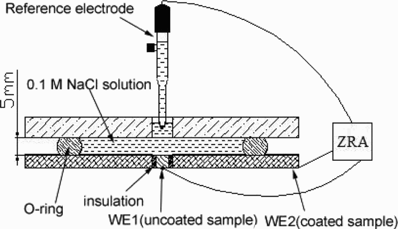
Schematic diagram of artificial scratch cell for coupling current measurement
Coupling current between the small uncoated sample WE1 and the large coated sample WE2 was monitored with a CST500 electrochemical galvanic corrosion instrument as a function of time at 10 Hz. During this coupling current monitoring process, the corrosion solution in the artificial solution was 0.1M NaCl solution.
During the coupling process, the EIS of the small uncoated sample was also detected. For easier detection of the EIS variation, a dilute Harrison's solution {0.05% NaCl+0.35% ammonium sulphate [(NH4)2SO4]} 23 was used in the artificial scratch cell. At sometime of the coupling process, the connection was removed, and the EIS of the small uncoated sample WE1 was measured.
After some days of coupling with the large coated sample WE2 in 0.1M NaCl solution, the corrosion morphology of the small uncoated sample WE1 was observed by a metallographic microscope and the SEM. The XPS measurements were also performed on the small uncoated sample WE1 to examine the deposited species.
Inductively coupled plasma optical emission spectroscopy (ICP-OES, Perkin-Elmer Optima 3000DV) was used to detect the presence of Cr and other dissolved species that might be released from the Cr(III) contained conversion coating to the solution in the artificial scratch cell. The detection sensitivity was part per billion level.
Results and discussion
Characterisation of conversion coating
The film was relatively evenly covering on the whole surface except around some secondary particles. It should be noted that the pits were formed during the pretreatment. Some cracks were found on the coating (Fig. 2), which may be associated with the SEM vacuum level or related to the dehydration of the coatings during the air drying process. 24
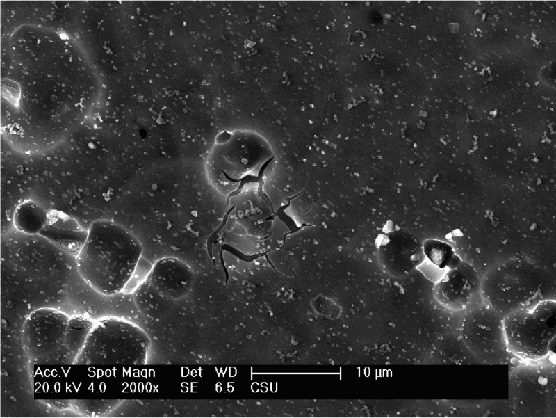
Image (SEM) of conversion coating
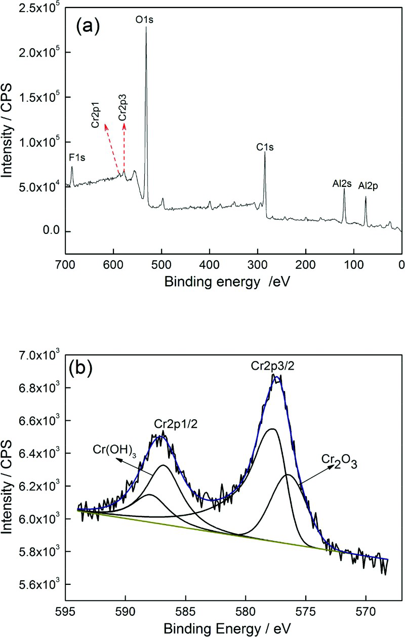
The XPS spectrum of the conversion coating is shown in Fig. 3. The overview spectrum showed signals of F, Cr, C, O and Zr (Fig. 3a). The signal of C was considered to be a contaminant, which may be deposited during the drying process exposure to ambient air or introduced by the experimental operation process. 24 Thus, the coating mainly contains F, Cr, O and Zr elements. A strong Zr3d signal was seen in the overview spectra, which had two peaks at the binding energy of ∼184.6 and 182.3 eV. This indicated that Zr mainly existed in the form of zirconium oxide, as shown in Fig. 3b.
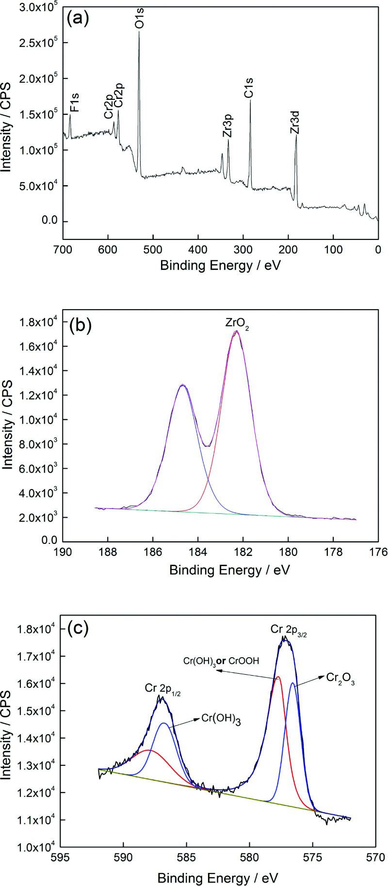
a overview XPS spectra, b Zr3d XPS spectra and c Cr2p XPS spectra of conversion coating
Two Cr peaks corresponding to Cr2p1/2 and Cr2p3/2 electron configurations were observed in the energy range of 570 to 595 eV. The Cr2p3/2 peak was sensitive to the Cr oxidation states, which could be fitted into two peaks. The fitted peak at 576.6 eV represented for Cr2O3 form and that at 577.7 eV for the form of Cr(OH)3 or CrOOH (Fig. 3c). 24 The Cr2p1/2 curve was also fitted into two peaks, which also represented for the Cr in the state Cr(III). The above detection showed that no Cr(VI) existed in the conversion coating.
Figure 4a shows the polarisation curves of the uncoated and coated samples in 3.5%NaCl solution at room temperature. It was clear that the conversion coating hinders not only the anodic process but also the cathodic process. The fitted corrosion parameters of corrosion potential E corr, corrosion current density i corr and polarisation resistance R p are listed in Table 1. The polarisation resistance of the coated sample was ∼4.5 times larger than the uncoated one. Accordingly, the i corr of the coated sample decreased greatly. This indicated that the corrosion resistance was effectively enhanced by the conversion coating.
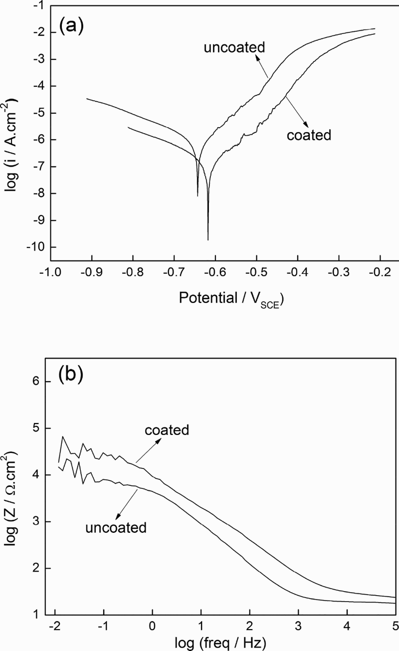
a polarisation curves and b EIS Bode plots of coated and uncoated samples in 3.5%NaCl solution
Corrosion parameters fitted through polarisation curves in Fig. 4a
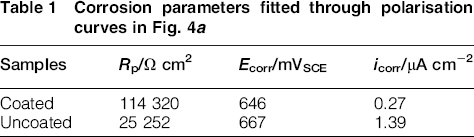
Figure 4b shows the EIS Bode plots of the uncoated and coated samples. The low frequency impedance modulus was considered to be proportional to the polarisation resistance, and higher modulus value indicated lower corrosion rate. 25 The corrosion resistance therefore can be characterised by the modulus value of the impedance at low frequency range. In the low frequency range from 10− 2 to 10− 1 Hz, the impedance modulus value of the coated sample was three times higher than that of uncoated sample. It meant that the corrosion resistance of the AA2024-T3 was obviously improved by the conversion coating.
The corrosion resistance enhancement of the coated sample was also verified by the neutral salt spray exposure. Figure 5 shows the macromorphologies of the uncoated and coated samples after exposure in salt fog for different time. After 48 h of exposure, extensive corrosion damage occurred on the uncoated specimen. Although the fresh substrate was still visible at some location, lots of black and white corrosion products were found on its surface, as shown in Fig. 5b. However, no obvious corrosion was observed on the coated specimen after the same exposure time of 48 h (Fig. 5e). With the exposure time extension to 192 h, sever corrosion occurred on the uncoated sample surface, and the whole surface was covered by heavy black and white corrosion products (Fig. 5c). Furthermore, many red copper coloured spots appeared, which probably resulted from the dissolution of Cu rich particles. However, only several corrosion pits appeared on the coated specimen surface after 192 h of exposure (Fig. 5f).
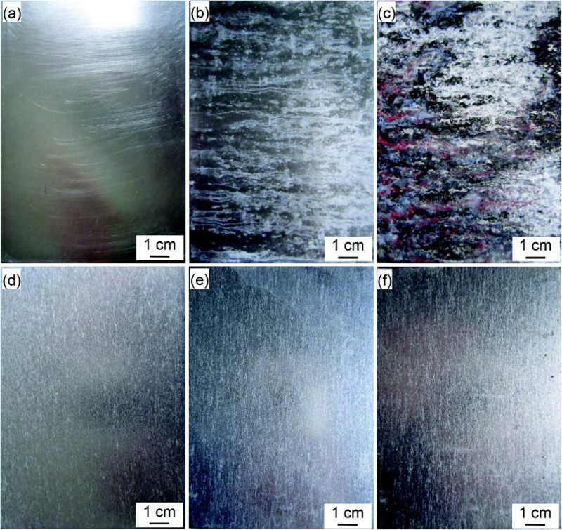
Macromorphologies of a–c uncoated and d–f coated samples after a,d 0 h, b,e 48 h and c,f 192 h exposure in salt fog
In addition to corrosion protection for metal substrate, conversion coatings are also applied to promote the adhesion of organic coatings to the metal substrate. Acrylic resin varnish was therefore painted on the uncoated and coated samples in this case, cross-scratches were prepared by a blade on their surfaces to simulate the coating defects (Fig. 6a1 and b1) and then these painted samples were exposed to salt fog. After 120 h of exposure in the salt spray, the whole cross-scratch on the painted sample without conversion coating was covered by heavy black and white corrosion products (Fig. 6a2). However, some fresh substrate was still visible at the scribe on the painted sample with conversion coating (Fig. 6b2), indicating that the conversion coating inhibited the corrosion of its adjacent scribe. As the exposure time was extended to 440 h, both the scribes were covered by heavy black corrosion products. However, blisters are corrosion induced next to the scribe on the painted surface without conversion coating (Fig. 6a3). Meanwhile, there were not any blisters on the painted sample with conversion coating (Fig. 6b3). These observations suggested the conversion coating improved the adhesion of the paint film to the alloy surface. On the other hand, it might possess self-repairing effect, which would be described in the following section.
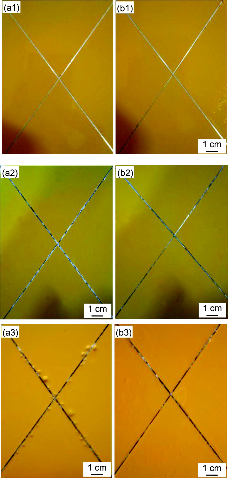
Macro-morphologies of painted samples before (a1, b1) and after120 h (a2,b2) and 440 h (a3, b3) of neutral salt fog exposure. (a1, a2, a3): painted on uncoated samples; (b1, b2, b3): painted on coated.
Self-repairing effect of conversion coating
After coupling for 9 days in the NaCl solution, the corrosion morphology of a small uncoated sample coupled with a large coated sample was observed by a metallographic microscope. Its corrosion degree was compared to that of an uncoated substrate immersed in the NaCl solution for 9 days. More and larger pits were found on the uncoated substrate immersed in the NaCl solution (Fig. 7a). On the surface of the small uncoated sample coupled with the large coated sample, the pit size was much smaller (Fig. 7b). Because the small uncoated sample was similar to a damage area on the conversion coating, this observation implied the self-repairing effect of the conversion coating.
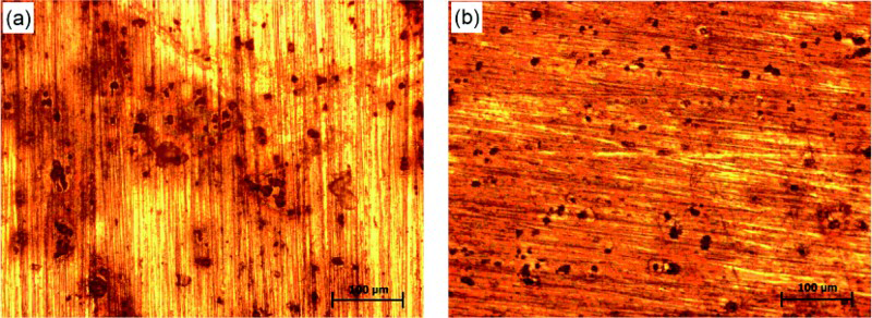
a uncoated substrate immersed in NaCl solution for 9 days; b small uncoated sample coupled with large coated sample in NaCl solution for 9 days
The self-repairing effect of the conversion coating was also verified by the EIS variation of the small uncoated WE1 coupled with the large coated WE2 in the Harrison solution. Figure 8 shows the EIS Bode (modulus) plots of the small uncoated WE1 at different time of coupling in the Harrision solution. Within 48 h of coupling, the impedance modulus values in low frequency range (10− 1–10− 2 Hz) increased gradually with coupling time. As the coupling time was extended from 10 min to 24 h and 48 h, the impedance modulus at 0.098 Hz was increased from ∼1.5 × 10⁵ Ω to 2.7 × 10⁵ Ω and 3.0 × 10⁵ Ω respectively. The low frequency impedance modulus could be served as an estimation of the corrosion resistance of a coated mental. 25 The increase in the low frequency impedance modulus in this case therefore indicated the corrosion resistance enhancement of the small uncoated WE1 with the coupling time. This phenomenon ascertained that the conversion coating repaired the nearby damaged area (small uncoated WE1) during this period. In other words, the conversion coating possessed a self-repairing effect. When the coupling time extended to beyond 72 h, the low frequency impedance modulus values reduced, the corrosion protection of the small uncoated WE1 provided by the surrounding conversion coating on WE2 was lowered.
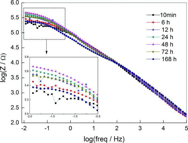
Electrochemical impedance spectroscopy Bode plots of small uncaoted WE1 coupled with large coated WE2 in artificial scratch cell containing Harrison solution
To further investigate the self-repairing effect of the conversion coating, the coupling current between a small uncoated sample (WE1) and a large coated sample (WE2) was monitored continuously for 15 days in neutral 0.1M NaCl solution. When the coupling current was positive, WE1 acted as anode and WE2 as cathode.
Figure 9 shows the baseline coupling current during the coupling process in 0.1M NaCl solution. With the coupling time extended, the current–time curve can be divided into three stages. At stage I, the baseline coupling current started with a positive value, and then oscillated between positive and negative value. During stage I (∼146 h), the small uncoated WE1 undertook anodic current for ∼86 h. It meant that during this stage, the small uncoated WE1 acted as anode and cathode alternatively, but mainly acted as anode in the coupling system, and corrosion mainly occurred on WE1. During stage II, the baseline coupling current kept stable at − 70 to − 75 nA, indicating that the small uncoated WE1 worked as cathode and was protected. During stage III, the baseline coupling was changed to positive and then increased up to ∼1000 nA, which implied that the small uncoated WE1 acted as anode again and its corrosion rate increased largely. In other words, the protection effect for the small uncoated WE1 provided by the conversion coatings was weakened, and corrosion on the small uncoated WE1 was dominant at the later stage of coupling. The above baseline coupling current variation suggested that during a certain coupling stage, the small uncoated WE1 was gradually protected by the adjacent large coated sample (WE2). That is to say, as the conversion coating was broken at some locations, the broken location (WE1) could be protected by the adjacent conversion coating (WE2).
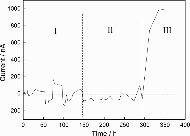
Coupling baseline current in 0.1M NaCl as function of time
There existed many transient currents along the baseline coupling current at different stages, as plotted in Figs. 10–13. There were some upward current transients appearing in the first day of coupling, of which the amplitude reached almost 1800 nA (Fig. 10a). The current transient showed a characteristic that it increased rapidly and then decreased fast. Meanwhile, some current transient peaks overlapped and possessed duration time longer than 150 s (Fig. 10b). It was reported that the rapid increase (decrease) followed by decrease (increase) in coupling current noise was attributed to the beginning and repassivation of pitting corrosion. 26 In this case, the current transient peak was in a positive direction. That is to say, the anodic current undertaken by the small uncoated WE1 was increased rapidly then decreased fast. Therefore, the upward current transients represented the beginning and repassivation of metastable pitting corrosion on the surface of the small uncoated WE1.
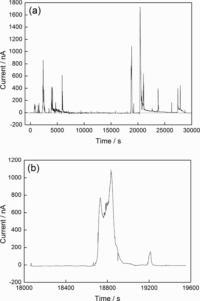
a coupling current curve and b typical current transient pattern at first day of coupling in 0.1M NaCl solution
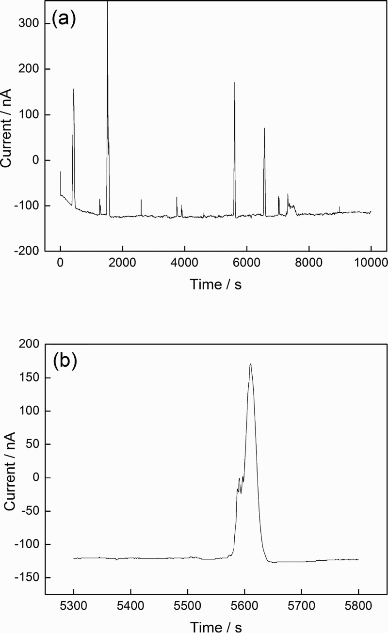
a coupling current curve and b typical current transient pattern at third day of coupling in 0.1M NaCl solution
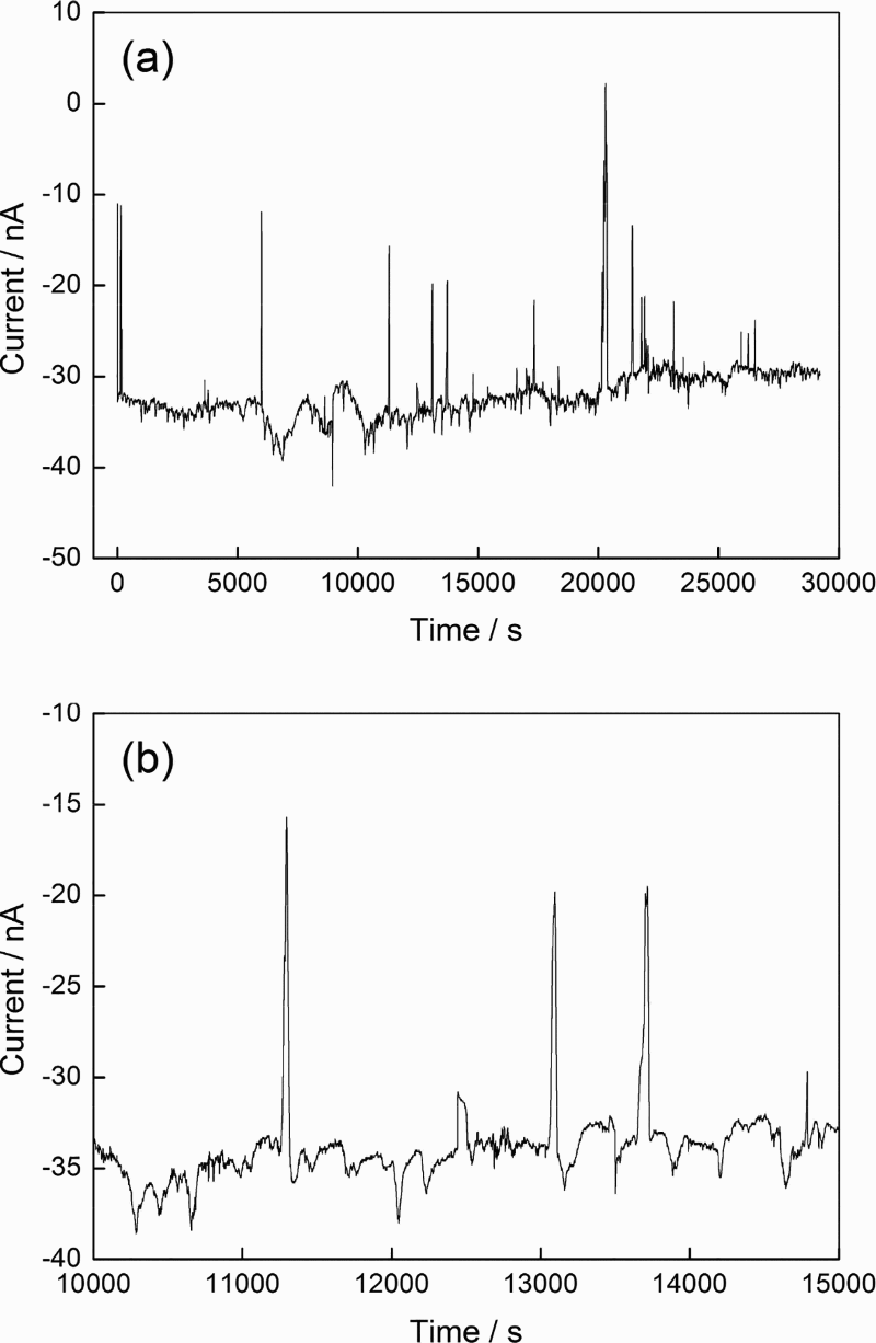
a coupling current curve and b typical current transient pattern at 10th day of coupling in 0.1M NaCl solution
a coupling current curve and b typical current transient pattern at 14th day of coupling in 0.1M NaCl solution
After 3 days of coupling, the baseline coupling current was changed to negative and sustained at − 115 to − 125 nA, and the upward current transients with a life span of ∼50 s also appeared (Fig. 11). However, the amplitude of the current transient peak was greatly decreased to 35-465 nA. The negative baseline current indicated that the small uncoated WE1 generally acted as cathode and was protected, but the upward current transient peaks implied that metastable pitting still occurred on its surface. Meanwhile, the metastable pitting degree was lowered, reflected by the smaller current peak amplitude.
As the coupling time was extended to 10 days (stage II), the baseline coupling current kept basically stable at − 30 to − 40 nA (Fig. 12a). The amplitude of the upward current transient peaks was further decreased to about 10-35 nA, but their duration time was still kept as about 50 s (Fig. 12b). The above coupling current feature indicated that during stage II, the small uncoated WE1 acted as cathode as a whole, and metastable pitting corrosion still occurred on its surface. In addition, the metastable pitting corrosion degree was greatly lowered compared to that during stage I.
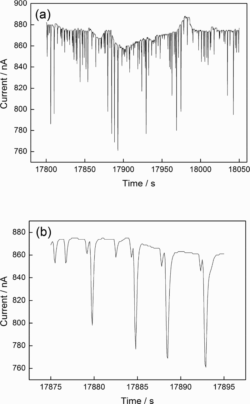
When the coupling time was further extended to 14 days (stage III), the baseline coupling current was changed to positive and then increased up to a high level about 860-880 nA (Fig. 13a). Meanwhile, the current transient was transferred to another form that the current decreased suddenly followed by a fast rise and its amplitude reached ∼100 nA (Fig. 13b). The positive baseline current indicated that the small uncoated WE1 acted as anode as a whole during stage III. The current transient peak in a negative direction implied a rapid decrease followed by a fast recovery in the anodic current of the small uncoated WE1. This should be corresponded to the beginning and repassivation of metastable pitting corrosion on the large coated WE2. Because if the metastable pitting corrosion occurred on the small uncoated WE1, the current transient peak should be in the positive direction. Meanwhile, the metastable pitting corrosion on the coated WE2 was much concentrated according to the current transient frequency.
Through the analysis of the baseline coupling current curves and the typical current transients, some characteristics can be summarised. At the initial stage, the small uncoated WE1 acted as anode and cathode alternatively, and metastable pitting corrosion occurred on its surface. With the coupling time extension, the small uncoated WE1 acted as cathode for a long period due to the self-repairing effect. As the coupling time was further extended, the repairing effect was weakened greatly and the corrosion degree of small uncoated WE1 was aggravated.
The corrosion morphology of the small uncoated WE1 after 15 days of coupling in 0.1M NaCl solution is shown in Fig. 14. There were some large irregular pits (A) and many round metastable pits (B and C) with different sizes. The radius of the type B pits was 2-6 μm, and that of type C pits was < 1 μm. It was reported that the amplitude of the transient current peaks reflected the growth rate of the metastable pits and higher amplitude of the transient current peaks corresponded to larger pits. 26 The metastable pits of type B and type C in this case therefore should be related to the upward current transients with high amplitude (Fig. 11b) and low amplitude (Fig. 12b) respectively. In addition, the larger irregular pits (type A) with different sizes might be corresponded to the positive baseline current or the current transient peak with the highest amplitude and a longer duration time (Fig. 10b). It should be emphasised that the above corrosion morphology dependence on the current transient pattern needs further in depth research.
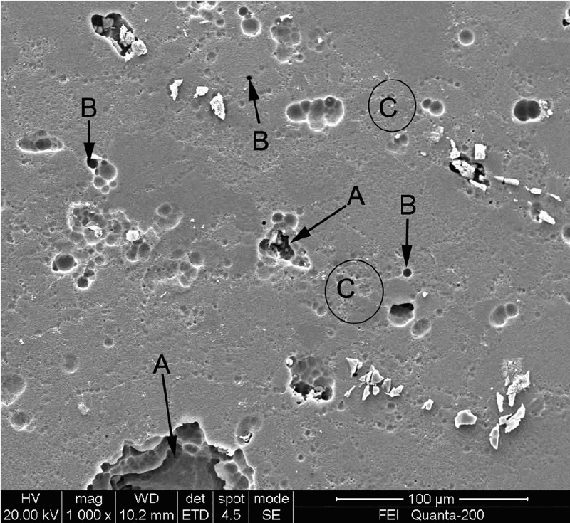
Image (SEM) of small uncoated WE1 after coupling with large coated WE2 for 15 days in 0.1M NaCl solution
To explain the repairing effect of the conversion coating, the solution was examined by the ICP-OES, in which the small uncoated WE1 and the large coated WE2 had been coupled for 4 days. The elements of Al, Cu and Cr were found; their concentrations were 1.189 ppm, 12 ppb and 226 ppb respectively. However, the Zr element was not found. Apparently, the Cr element rather than Zr element was released into the solution from the conversion coating during the coupling process. In other words, Cr in the conversion coating had the mobility, which supported its self-repairing capability.
After coupling for 9 days, the surface of the small uncoated sample WE1 was also detected by XPS, as shown in Fig. 15. The Zr element was not found, but Cr element was detected on the surface. The Cr2p had two peaks at the binding energy of 577 and 586 eV, which represented the two states of Cr2p3/2 and Cr2p1/2 respectively (Fig. 15b). The Cr2p3/2 peak was fitted into two peaks, the corresponding binding energy was 577.4 and 580.3 eV respectively. According to the NIST Standard Reference Database, the main fitted peak at 577.4 eV corresponded to the Cr(III) compound Cr(OH)3, the small fitted peak at 580.3 eV might correspond to Na2CrO4. The Cr2p1/2 peak was also fitted into two peaks; the corresponding binding energies were 583.6 and 587.1 eV respectively. The peak at 587.1 eV corresponded to the Cr(III) compound of Cr2O3.
a overview XPS spectra and b Cr2p XPS spectra of small uncoated sample (WE1) coupled with large coated sample for 9 days
The above ICP-OES analysis and XPS detection indicated that Cr but not Zr in conversion coating was released to the solution, transferred to the adjacent uncoated WE1 (simulated scratch area) and then deposited mainly as Cr(III) compounds. The deposited Cr(III) compound therefore provided protection for the small uncoated WE1. In other words, the self-repairing effect was originated from Cr(III) in the conversion coating.
Conclusions
The Cr(III) contained conversion coating on AA2024-T3 alloy was prepared in conversion bath containing Cr2(SO4)3 and K2ZrF6. Its corrosion resistance was investigated. Meanwhile, its self-repairing behaviour was studied by coupling experiment between a small uncoated sample and a large coated sample in an artificial scratch cell. The conclusions are as follows.
The conversion coating is a Cr(III) contained conversion coating, which mainly consists of zirconium oxide and Cr(III) oxide and hydroxide. Furthermore, there is no Cr(VI) compound in the coating. The conversion coating hinders not only the anodic process but also the cathodic process, and therefore improves corrosion resistance effectively. When exposed to neutral 5%NaCl salt fog, it shows corrosion resistance in excess of 192 h. Cr element rather than Zr is found in the artificial scratch cell. Meanwhile, Cr(III) compounds are deposited on the small uncoated sample coupled with large coated sample in the artificial scratch cell. The conversion coating possesses self-repairing effect, which is generated from the release of Cr species from the coating, migration and then deposition to the nearby scratch area.
Footnotes
Acknowledgements
The authors wish to acknowledge the financial support of The Project sponsored by SRF for ROCS, SEM.